EP4351781B1 - Abgedichtete doppeltür-verbindungsvorrichtung mit verstärkter sicherheit - Google Patents
Abgedichtete doppeltür-verbindungsvorrichtung mit verstärkter sicherheit Download PDFInfo
- Publication number
- EP4351781B1 EP4351781B1 EP22735555.9A EP22735555A EP4351781B1 EP 4351781 B1 EP4351781 B1 EP 4351781B1 EP 22735555 A EP22735555 A EP 22735555A EP 4351781 B1 EP4351781 B1 EP 4351781B1
- Authority
- EP
- European Patent Office
- Prior art keywords
- flange
- door
- connection device
- container
- connection
- Prior art date
- Legal status (The legal status is an assumption and is not a legal conclusion. Google has not performed a legal analysis and makes no representation as to the accuracy of the status listed.)
- Active
Links
Images



Classifications
-
- B—PERFORMING OPERATIONS; TRANSPORTING
- B01—PHYSICAL OR CHEMICAL PROCESSES OR APPARATUS IN GENERAL
- B01L—CHEMICAL OR PHYSICAL LABORATORY APPARATUS FOR GENERAL USE
- B01L1/00—Enclosures; Chambers
- B01L1/02—Air-pressure chambers; Air-locks therefor
-
- G—PHYSICS
- G21—NUCLEAR PHYSICS; NUCLEAR ENGINEERING
- G21F—PROTECTION AGAINST X-RADIATION, GAMMA RADIATION, CORPUSCULAR RADIATION OR PARTICLE BOMBARDMENT; TREATING RADIOACTIVELY CONTAMINATED MATERIAL; DECONTAMINATION ARRANGEMENTS THEREFOR
- G21F7/00—Shielded cells or rooms
- G21F7/005—Shielded passages through walls; Locks; Transferring devices between rooms
-
- B—PERFORMING OPERATIONS; TRANSPORTING
- B01—PHYSICAL OR CHEMICAL PROCESSES OR APPARATUS IN GENERAL
- B01L—CHEMICAL OR PHYSICAL LABORATORY APPARATUS FOR GENERAL USE
- B01L2200/00—Solutions for specific problems relating to chemical or physical laboratory apparatus
- B01L2200/06—Fluid handling related problems
- B01L2200/0689—Sealing
-
- B—PERFORMING OPERATIONS; TRANSPORTING
- B01—PHYSICAL OR CHEMICAL PROCESSES OR APPARATUS IN GENERAL
- B01L—CHEMICAL OR PHYSICAL LABORATORY APPARATUS FOR GENERAL USE
- B01L2200/00—Solutions for specific problems relating to chemical or physical laboratory apparatus
- B01L2200/14—Process control and prevention of errors
- B01L2200/143—Quality control, feedback systems
- B01L2200/145—Detecting door closure
Definitions
- the present invention relates to a double-door connection device with enhanced security.
- Such a double-door device equipped with a multiple safety control is for example known from the document FR 2 695 343
- Each volume is closed by a door mounted in a flange.
- Each door is secured to its flange either by a bayonet connection or by a hinge and a locking system and the two flanges are intended to be secured to each other by a bayonet connection.
- one of the closed volumes is formed by an isolator and the other volume is formed by a flexible container, also called a waterproof transfer bag.
- connection part carried by the insulator is designated alpha part and the connection part carried by the container is designated beta part.
- Gaskets are provided on the alpha part and on the beta part to ensure sealing between the connected volumes.
- the beta part has a beta flange closed by a beta gate, the beta flange and the beta gate cooperating with each other by a bayonet connection, and the alpha part has an alpha flange closed by an alpha gate, the alpha gate being hinged to the alpha flange by a hinge.
- the seal between the beta flange and the beta door is ensured by a seal housed in the beta flange.
- connection between the transfer bag and the enclosure is made by mechanical cooperation of the beta flange and the alpha flange by a bayonet type connection. This mechanical cooperation ensures both the mechanical connection and the sealing.
- the waterproof connection cycle is as follows: The container carrying the beta part is brought closer to the alpha part, the ears of the beta flange enter notches in the alpha flange, and the ears of the beta door enter notches in the alpha door.
- the container is rotated, for example clockwise, the ears of the beta flange pivot and slide in a groove in the alpha flange.
- the rotation of the container causes the rotation of the beta door, which causes the connection between the beta door and the alpha door by the bayonet connection.
- the two doors are then secured. Each ear of the beta door then comes to bear against a circumferential stop carried by the alpha door.
- the container is still rotated, due to the beta gate ears pressing against the circumferential stops on the alpha gate, the rotation of the container causes the disconnection between the beta gate and the beta flange.
- the following alternative is possible: Simultaneously with the pivoting and sliding of the ears of the beta flange in a groove of the alpha flange, due to the friction of the seal carried by the alpha door, the beta door is kept stationary in rotation and the beta door is disconnected from the beta flange. Each ear of the beta flange then comes to bear against a circumferential stop carried by the beta door.
- the container is still rotated, due to the support of the ears of the beta flange against the circumferential stops on the beta door, the rotation of the container causes the rotation of the beta door, which causes the connection between the beta door and the alpha door by the bayonet connection. The two doors are then secured.
- the alpha door is unlocked and the entire assembly of two doors can be pivoted towards the inside of the cell around the hinge axis.
- Transfer between the two volumes can take place.
- the disconnection cycle is as follows: Both doors are replaced in the flanges.
- the container is rotated counterclockwise. Due to friction between the gates, the beta gate remains stationary in rotation, causing the beta gate and the beta flange to connect. Then, circumferential stops carried by the beta flange bear against the circumferential stops of the beta gate, causing the beta gate to rotate relative to the alpha gate and disconnect them. The container is also disconnected from the alpha flange. The container can then be removed from the flange.
- a number of safety features are implemented to limit the risk of the enclosure being opened when the container is not properly connected to the alpha part.
- a double-door device equipped with a multiple safety control is, for example, also known from the document EP 2 766 121 .
- This device comprises a manual control member for opening the doors and four locks, two of which prevent any opening maneuver until the container door is present and until the container flange is fully connected to the alpha flange.
- a third lock prevents any disconnection of the two flanges after the control member has passed an intermediate locking position.
- a fourth lock prevents the control member from returning to its initial position when the doors are open. This double-door connection device is satisfactory.
- the first two locks are at least partially deactivated when the connection of one of the ears of the beta flange to the alpha flange is detected.
- a protruding rod of the alpha flange is pushed back by the ear of the beta flange, which contributes to the deactivation of the two locks.
- Beta flanges can deteriorate, for example, become deformed or even break during transport. manipulations, including the alpha flange connection ears that extend radially outward from the flange.
- the inventor has found that if one or more of the three other ears of the container whose presence is not detected are damaged, for example broken or deformed, and the ear whose presence is detected is in a sufficient condition to ensure the deactivation of the locks, the cell door lock may be deactivated, while the connection is not necessarily secure due to the deterioration of one or the other ears. Indeed, this partial deterioration may result in poor application of the seal against the alpha flange and therefore a risk of a leak, which may cause a loss of containment.
- FR 2 441 244 describes an example of a known sealed connection device.
- a double door sealed connection device which comprises a cell flange and a door, the cell flange comprising bayonet connection means intended to cooperate with a flange of an object to be connected, the flange of the object comprising ears cooperating with the bayonet connection means, said cell flange comprising means for detecting the presence of each of the ears of the flange of the object to be connected.
- the sealed connection device comprises motorized unlocking means, the detection of the presence of all the ears then results in the sending of a signal to control means which generate an order to the unlocking means to unlock. Conversely, if one of the ears is not detected, unlocking is prohibited.
- the detection of the presence of each ear is carried out by an inductive sensor.
- the present application then relates to a sealed connection device for a double-door connection system comprising a first flange and a first door closing said first flange, said first flange comprising bayonet connection means for an object, said object comprising a second flange closed by a second door, the second flange being provided with n ears intended to cooperate with the bayonet connection means of the first flange, said first flange comprising n detectors for the correct assembly of the ears of the second flange in the bayonet connection means, each detector being configured for detecting the presence of an ear.
- the first flange comprises for each ear a rotation stop configured to stop the rotation of the second flange in a connection position, and each detector is upstream of the rotation stop in a direction of connection of the second flange to the first flange.
- Each detector may comprise an element configured to be moved by the presence of the ear and a sensor for detecting the movement of the element.
- the element may be a rod capable of sliding radially, one longitudinal end of the rod being pushed radially outwards by the ear, another longitudinal end of the rod being detected by the sensor, and elastic return means exerting a force radially inwards on the element.
- the element is metallic and the sensor is an inductive sensor.
- each detector comprises a fixing bracket in which the sensor is mounted and the rod capable of sliding in the fixing bracket is mounted.
- the detectors and the related electrical connection means are housed in an interior volume of the first flange.
- Another subject of the present application is an enclosure defining a first closed volume and comprising a sealed connection device according to the invention, said connection device being mounted in a wall of said enclosure.
- the enclosure may include a control unit to which the detectors are connected.
- the control unit is advantageously configured to emit an alert message if one of the detectors does not send an ear detection signal.
- the object can be a container or a flexible bag.
- cell door and “alpha door” are synonymous
- the terms “container door” and “beta door” are synonymous
- the terms “cell flange” and “alpha flange” are synonymous
- the terms “container flange” and “beta flange” are synonymous.
- the beta flange is that of a container intended to be connected in a sealed manner to an alpha flange for the purpose of transferring objects between the interior of the container and the interior of the cell.
- the connection device is suitable for the sealed connection of any object equipped with a beta flange, for example it may be soft bags, gloves, sleeves, half-suits, etc.
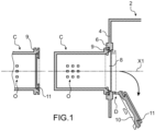
- FIG. 1 a schematic representation of a double-door sealed transfer system can be seen in which a sealed connection device according to the invention can be implemented.
- the double-door transfer system has a symmetry of revolution around the X1 axis which is the axis of the cell flange
- the two closed volumes that we wish to connect correspond respectively to an isolator 2 or cell and to a container C.
- the container has a rigid container part.
- it has a flexible container part.
- the enclosure 2 comprises walls delimiting a sealed volume. At least one of the walls 4 comprises a sealed connection device D to a system sealed exterior, for example another enclosure, a rigid or flexible container, such as a bag.
- the device D is intended to allow the interior volumes of the enclosure and the exterior system to be connected in a sealed manner and to allow a sealed transfer between the two volumes, to protect the objects contained in the sealed volumes and/or to protect the external environment from these objects.
- the enclosure 2 may be part of an isolator system, in particular an isolator containment area, a sterile containment area or a radioactive containment area, which may be used to manufacture products in the pharmaceutical, food or nuclear industries, for example.
- sealed connection devices are described in the document FR 2 695 343 and in the document EP 2 766 121 .
- the sealed connection device D comprises a cell flange 6 mounted in the wall 4 of the cell and delimiting an opening 8, a door 10 intended to seal the opening 8.
- the sealed connection device D also comprises means for connection to an external system, for example a container C, also comprising a container flange 9 bordering an opening and a door 11 sealingly closing said opening.
- the connection means of the cell flange 6 and the flange 9 are for example of the bayonet type.
- Each door is connected to its flange also by a bayonet connection or by a pivot connection with a hinge.
- the connection device has a symmetry of revolution of axis X1.
- FIG. 1 An example of a procedure for tightly connecting a container to the enclosure will be briefly described using the Figure 1 .
- the closed container is shown in dotted lines before its connection to the enclosure.
- the container contains objects O, represented schematically, which we wish to transfer into the enclosure. The transfer system is not shown.
- the container flange 9 is tightly secured to the enclosure flange 6 by means of a bayonet connection. Simultaneously, the container door 11 and the enclosure door 10 are tightly secured to each other by a bayonet connection.
- the outer faces of the doors 10, 11 are insulated by relative to the interior volume of the container and the enclosure, the assembly formed by the two doors 10, 11 secured to each other can be removed by pivoting it around its axis, and then moved into the enclosure, freeing up a passage between the two volumes. The two volumes are then in sealed communication and the transfer of objects between the two volumes can be carried out through the passage.
- the flange 9 of the container has a seal which comes into contact with the outer face of the flange 6 of the enclosure; this seal helps to delimit the passage between the two volumes.
- Means make it possible to control the opening and closing of the doors 10 and 11. These means can be manual or automated as will be described in more detail later in the description.
- the container door 11 is fixed to the container flange 9 by a bayonet connection.
- the double-door sealed transfer system also comprises two other bayonet connections, to allow the container flange 9 to be secured to the cell flange 6 and the container door 11 to be secured to the cell door 10.
- the three bayonet connections are arranged in such a way that after the container flange 9 has been docked on the cell flange 6, a rotation of the container C around its axis, for example in the clockwise direction, has the effect of securing the container flange 9 and the cell flange 6, securing the container door 11 and the cell door 10, and detaching the container door 11 from the container flange 9.
- these last two operations are carried out consecutively, so that the container is opened only after the container door 11 has been secured to the cell door 10 to form a double door.
- the assembly formed by the cell flange and the cell door is commonly referred to as the “alpha part”.
- the assembly formed by the container flange 9, the container door 11 and the seal mounted on the flange 9, and which ensures both the seal between the flange and the container door 11 and between the cell flange 6 and the container flange 9, is commonly referred to as the “beta part”.
- the transfer container then has a beta connection part and a container.
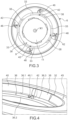
- FIG. 2A we can see an interior volume 30 of a cell flange 6 or alpha flange according to an exemplary embodiment.
- this volume 30 is located inside the flange and oriented towards the outside of the cell. It is closed by a protective cover 31 ( Figure 2B ).
- the detectors 46 and the related electrical connection means 58 are housed in the interior volume 30; they do not represent an additional surface area that would hinder the operator.
- the flange 6 comprises bayonet connection means 32 configured to cooperate with ears 33 of the container flange 9.
- the ears 33 can be seen extending radially outwardly from the container flange 9.
- the container flange has four ears. Alternatively, it has three or more ears.
- the bayonet connection means 32 can be seen comprising a radial groove 36 opening radially towards the central passage of the cell flange.
- the radial groove 36 is delimited by two side walls 36.1, 36.2 and a bottom 36.3.
- the side walls are substantially perpendicular to the axis of the cell flange 6 and the bottom 36.3 extends axially around the longitudinal axis X1.
- the side wall 36.1 located upstream relative to the direction of insertion of the container flange into the cell flange, comprises radial notches 38 distributed angularly around the longitudinal axis X1.
- the radial notches 38 are arranged and dimensioned so as to allow the lugs 33 to pass through the groove and to be inserted into the groove.
- the radial notches 38 are separated by portions of circular arcs 40 forming axial stops for the ears 32.
- the cell flange also has rotation stops 42 ( figures 4 to 6 ) arranged in the radial groove 36 and limiting the rotational movement of the ears 33 around the axis X1 in a direction of rotation of connection of the container flange 9 in the cell flange 6.
- each stop in rotation 42 is located at an angular end of each radial notch 38, so as to be located downstream of the ear intended to come into abutment against it in the connection phase.
- the cell flange 6 also has a circular groove 45 ( Figure 6 ) of axis X1 delimiting the interior volume 30 and surrounding the radial groove 36.
- the bottom 36.3 of the groove 36 forms the radially interior wall of the groove 45.
- the cell flange 6 also includes detectors 46 for the presence of each of the ears 33 of the container flange in the groove 36.
- the cell flange 6 therefore comprises as many detectors 46 as there are ears of the container flange.
- the cell flange comprises four detectors 46.
- Each detector 46 is mounted on the cell flange, upstream of a rotation stop 42.
- the detectors 46 are mounted in the interior volume 30 of the cell flange, on the outside of the enclosure.
- the detector 46 comprises a detection element formed by a rod 48 mounted in a bore 50.
- the rod 48 opens through one end 48.1 into the radial groove 36 and through another end 48.2 into the circular groove 45.
- the bore 50 is oriented radially.
- the rod 48 is slidably mounted in the bore 50.
- the first end 48.1 of the rod 48 is intended to be in contact with a radially outer edge of an ear 33 of the container flange 9 and forms a feeler.
- the feeler 48.1 has a beveled face 49 facilitating its cooperation with the ear 33.
- the beveled face 49 has a leading end 49.1 with which the ear will come into contact during its rotation. In the rest state, the leading end 49.1 is flush with the bottom 36.3 of the radial groove.
- the second end 48.2 of the rod 48 opens into the circular groove 45 and is intended to be detected by a sensor 52 fixed in the circular groove 45 of the cell flange.
- the sensor is arranged substantially perpendicular to the rod.
- the end 48.2 moving between a rest position, in which it is not detected by the sensor ( Figure 7A ) and a detection position, in which it is detected by the sensor ( Figure 7B ).
- Another relative orientation of the sensor 52 and the rod 48 does not depart from the scope of the present invention.
- the end 48.2 advantageously comprises a flat facing the inductive sensor 52 to provide a flat surface facing the inductive sensor 52 and not a cylinder generator.
- the senor 52 is an inductive sensor and the rod 48 or at least its second end 48.2 is made of a metallic material detectable by the inductive sensor.
- the end 48.2 of the rod is opposite the sensor ( Figure 7B )
- the sensor 52 is mounted in a fixing support 54 fixed to the cell flange 6 and the rod 48 is also slidably mounted in the fixing support 54.
- the fixing support 54 has the general shape of an L, one branch of the L carrying the sensor and the other branch carrying the rod 48.
- the fixing support 54 is for example fixed to the flange by means of a screw 56.
- the implementation of a fixing support 54 securing the sensor and the rod 48 allows simultaneous and easy mounting of the sensor 52 and the rod 48 on the flange 6, for example by means of a single screw. In addition, their relative orientation is fixed by the fixing support.
- Elastic return means in the rest position are provided (not shown). They are for example formed by a helical spring mounted in the fixing support or between the fixing support 54 and the bottom of the radial groove 36.
- the detectors described above are robust due to their simplicity. They have only one moving element, so the risk of failure is reduced.
- the senor 52 is electrically connected by a cable 58 to a power source G and to a control unit UC which receives and uses the signals emitted by the sensor.
- the cable is used only for power supply and the signals are transmitted wirelessly, for example by radio waves.
- the sensors 52 are electrical switches, optical sensors implementing for example laser detection in barrage or detection.
- the detection is a purely mechanical detection, in which the movements of the rods 48 resulting from the correct positioning of the beta container cause the mechanical unlocking of the cell door. The opening of the doors is controlled elsewhere.
- a linkage system makes it possible to recover the movements of all the rods and to transform them into an unlocking action if necessary.
- the sensor comprises an indicator light 60 which changes its lighting state depending on whether or not the rod is detected.
- the indicator light lights up when the rod is detected.
- a light visible to the operator indicates the connection status.
- the four sensors are arranged at 90° to each other. If three sensors were implemented, they would typically be arranged at 120° to each other.
- the n sensors implemented to detect the n ears of the container flange have the same angular arrangement as the n ears of the container flange.
- the means for unlocking and for actuating the opening and closing of the doors 10 and 11 are automated.
- the means for unlocking and for actuating the doors comprise a first electric motor controlling the locking/unlocking of the cell door, and a second electric motor moving the cell door and the container door attached to it, around the hinge of the cell door.
- the control unit sends signals to the first motor to control the unlocking of the cell door, and to the second motor to control the opening of the doors. These signals are only sent if the four sensors detect the four rods. If at least one detection signal is not emitted, no unlocking or opening is permitted. It should be noted that the presence of the container door is also detected by means provided for this purpose.
- the operator axially approaches the container flange 9 to the cell flange 6 and causes the ears 33 of the container flange 9 to penetrate into the notches 38 formed in the side wall 36.1 of the radial groove 36 of the cell flange 6.
- the axis of the cell flange and the axis of the container flange are aligned.
- the sensors detect the movement of the rods and each emit a detection signal to the control unit ( Figure 7B ), the control unit issues an order to the lock motor to unlock the cell door and to the opening motor to open the doors.
- the invention offers a high level of safety since the risks of breaking the sealed atmosphere due to a defective flange are avoided.
- the container is sent to scrap or for repair.
- the present invention also applies to cells in which the unlocking of the cell door and/or the opening of the cell door and the container door are carried out manually.
- the operator accesses the lock using a glove mounted in a glove ring located near the cell flange.
- the control unit depending on the signals emitted by the sensors, releases a stop preventing unlocking, which is then carried out by the operator.
- it is the operator who decides to unlock the cell door based on the information sent by the detectors. If the operator detects that all the sensors emit an ear detection signal, he decides to unlock the cell door, otherwise he removes the container for disposal or repair.
Landscapes
- Health & Medical Sciences (AREA)
- Chemical Kinetics & Catalysis (AREA)
- Chemical & Material Sciences (AREA)
- Clinical Laboratory Science (AREA)
- High Energy & Nuclear Physics (AREA)
- Physics & Mathematics (AREA)
- General Engineering & Computer Science (AREA)
- Engineering & Computer Science (AREA)
- Pressure Vessels And Lids Thereof (AREA)
- Closures For Containers (AREA)
- Seal Device For Vehicle (AREA)
- Connector Housings Or Holding Contact Members (AREA)
- Power-Operated Mechanisms For Wings (AREA)
- Burglar Alarm Systems (AREA)
Claims (12)
- Wasserdichte Verbindungsvorrichtung für ein Doppeltür-Verbindungssystem mit einem ersten Flansch (6) und einer ersten Tür (10), die den ersten Flansch (6) verschließt, wobei der erste Flansch (6) Bajonettverbindungsmittel für ein Objekt aufweist, wobei das Objekt einen zweiten Flansch (9) aufweist, der durch eine zweite Tür (11) verschlossen ist, wobei der zweite Flansch (9) mit n Ösen (33) versehen ist, die mit den Bajonettverbindungsmitteln des ersten Flansches (6) zusammenarbeiten sollen, wobei der erste Flansch (6) n Detektoren der korrekten Montage der Ösen (33) des zweiten Flansches (9) in den Bajonettverbindungsmitteln umfassen, wobei jeder Detektor (46) für die Erkennung des Vorhandenseins einer Öse (33) eingerichtet ist.
- Verbindungsvorrichtung nach Anspruch 1, wobei der erste Flansch (6) für jede Öse einen Drehanschlag (42) aufweist, der so eingerichtet ist, dass er den zweiten Flansch (9) in einer Verbindungsposition in Drehung stoppt, und wobei jeder Detektor (46) dem Drehanschlag (42) in einer Verbindungsrichtung des zweiten Flansches (9) auf dem ersten Flansch (6) vorgeschaltet ist.
- Verbindungsvorrichtung nach Anspruch 1 oder 2, wobei jeder Detektor (46) ein Element (48) umfasst, das so eingerichtet ist, dass es durch das Vorhandensein der Öse (33) bewegt wird, und einen Sensor (52), um die Bewegung des Elements (48) zu erkennen.
- Verbindungsvorrichtung nach Anspruch 3, wobei das Element (48) ein radial verschiebbarer Stab ist, wobei ein Längsende (48.1) des Stabs (48) von der Öse radial nach außen gedrückt wird, wobei ein anderes Längsende (48.2) des Stabs (48) vom Sensor (52) erfasst wird, und wobei elastische Rückstellmittel eine radial nach innen gerichtete Kraft auf das Element (48) ausüben.
- Verbindungsvorrichtung nach Anspruch 4, wobei das Element (48) metallisch ist und der Sensor ein induktiver Sensor ist.
- Verbindungsvorrichtung nach Anspruch 4 oder 5, wobei jeder Detektor einen Befestigungshalter aufweist, in dem der Sensor montiert ist und der in den Befestigungshalter gleitfähige Stab montiert ist.
- Verbindungsvorrichtung nach einem der Ansprüche 1 bis 6, wobei die Detektoren (46) und die zugehörigen elektrischen Verbindungsmittel in einem Innenvolumen (30) des ersten Flanschs (6) untergebracht sind.
- Gehäuse, das ein erstes geschlossenes Volumen definiert und eine dichte Verbindungsvorrichtung nach einem der vorhergehenden Ansprüche aufweist, wobei die Verbindungsvorrichtung (D) in einer Wand (4) des Gehäuses montiert ist.
- Gehäuse nach Anspruch 8, das eine Steuereinheit aufweist, an die die Detektoren (46) angeschlossen sind.
- Gehäuse nach dem vorhergehenden Anspruch, mit motorisierten Verriegelungs-/Entriegelungsmitteln der ersten Tür (10) und motorisierten Öffnungsmitteln der ersten Tür (10), die mit der Steuereinheit verbunden sind, wobei die Steuereinheit (UC) eingerichtet ist, wenn der zweite Flansch (9) an dem ersten Flansch (6) montiert ist, zur Steuerung der motorischen Verriegelungsmittel und der motorischen Öffnungsmittel, wenn die n Sensoren jeweils ein Erkennungssignal von einer Öse an die Steuereinheit senden.
- Gehäuse nach Anspruch 9 oder 10, wobei die Steuereinheit (UC) so eingerichtet ist, dass sie eine Warnmeldung ausgibt, wenn einer der Detektoren (46) kein Signal zur Erkennung einer Öse sendet.
- Gehäuse nach einem der Ansprüche 8 bis 11, wobei der Objekt ein Behälter oder ein weicher Beutel ist.
Applications Claiming Priority (2)
| Application Number | Priority Date | Filing Date | Title |
|---|---|---|---|
| FR2106197A FR3123934B1 (fr) | 2021-06-11 | 2021-06-11 | Dispositif de connexion étanche a double porte a sécurité renforcée |
| PCT/FR2022/051091 WO2022258926A1 (fr) | 2021-06-11 | 2022-06-08 | Dispositif de connexion étanche a double porte a sécurité renforcée |
Publications (2)
| Publication Number | Publication Date |
|---|---|
| EP4351781A1 EP4351781A1 (de) | 2024-04-17 |
| EP4351781B1 true EP4351781B1 (de) | 2025-05-07 |
Family
ID=77180185
Family Applications (1)
| Application Number | Title | Priority Date | Filing Date |
|---|---|---|---|
| EP22735555.9A Active EP4351781B1 (de) | 2021-06-11 | 2022-06-08 | Abgedichtete doppeltür-verbindungsvorrichtung mit verstärkter sicherheit |
Country Status (9)
| Country | Link |
|---|---|
| US (1) | US12564832B2 (de) |
| EP (1) | EP4351781B1 (de) |
| JP (1) | JP2024529233A (de) |
| CN (1) | CN117615847A (de) |
| AU (1) | AU2022289136A1 (de) |
| BR (1) | BR112023025933A2 (de) |
| CA (1) | CA3222097A1 (de) |
| FR (1) | FR3123934B1 (de) |
| WO (1) | WO2022258926A1 (de) |
Families Citing this family (2)
| Publication number | Priority date | Publication date | Assignee | Title |
|---|---|---|---|---|
| DE102020215620A1 (de) * | 2020-12-10 | 2022-06-15 | Castus GmbH & Co. KG | Türvorrichtung zum Anschließen eines Behälters an einen Isolierraum |
| DE102023111765A1 (de) * | 2023-05-05 | 2024-11-07 | KyooBe Tech GmbH | Transfervorrichtung |
Family Cites Families (43)
| Publication number | Priority date | Publication date | Assignee | Title |
|---|---|---|---|---|
| US2816683A (en) * | 1953-05-11 | 1957-12-17 | Pullman Standard Car Mfg Co | Hatch cover and lock |
| FR2441244B1 (fr) * | 1978-11-06 | 1987-02-13 | Atomic Energy Authority Uk | Dispositif d'acces pour le transfert de matieres toxiques ou radioactives entre un recipient et une enceinte |
| FR2496325B1 (fr) * | 1980-12-16 | 1987-05-22 | Calhene | Dispositif de securite pour systeme de verrouillage entre deux enceintes etanches |
| US4622902A (en) * | 1984-07-30 | 1986-11-18 | Miller Roy W | Hatch cover and locking structure |
| US4570816A (en) * | 1984-10-10 | 1986-02-18 | Pullman Standard, Inc. | Hatch cover and locking structure |
| US4889056A (en) * | 1985-03-27 | 1989-12-26 | Trinity Industries, Inc. | Cover and latching mechanism for rail car loading hatch |
| US4684491A (en) * | 1986-01-09 | 1987-08-04 | Westinghouse Electric Corp. | Nozzle seal retaining assembly and positioning assembly therefor |
| US4928615A (en) * | 1989-03-27 | 1990-05-29 | Williams John E | Hatch cover |
| US4941695A (en) * | 1989-05-18 | 1990-07-17 | Pullman Leasing Company | Hatch cover assembly |
| US4944233A (en) * | 1989-06-12 | 1990-07-31 | Acf Industries, Incorporated | Hatch arrangement for covered hopper cars |
| US4948185A (en) * | 1989-08-21 | 1990-08-14 | Pullman Leasing Company | Hatch cover assembly |
| US5396692A (en) * | 1991-10-28 | 1995-03-14 | Fmc Corporation | Non-linear torsional assist mechanism and method |
| FR2695343B1 (fr) * | 1992-09-04 | 1994-11-25 | Sne Calhene | Mécanisme de commande centralisé, à sécurités incorporées, pour un dispositif de transfert étanche entre deux volumes clos. |
| US5660295A (en) * | 1995-03-06 | 1997-08-26 | Gpe Controls, Inc. | Covers for gauging and sampling openings |
| FR2735190B1 (fr) * | 1995-06-09 | 1997-08-29 | Calhene | Dispositif de raccordement deconnectable de deux pieces selon un contour non circulaire et notamment ovale. |
| US6095365A (en) * | 1998-08-24 | 2000-08-01 | The Heil Company | Pivoting hatch cover assembly |
| US6109823A (en) * | 1998-11-20 | 2000-08-29 | Stebbins Engineering & Manufacturing Co. | Method of converting existing tank access ways |
| FR2787190B1 (fr) * | 1998-12-11 | 2001-02-16 | Becton Dickinson France | Dispositif de detection de l'etancheite de la liaison entre les elements d'un dispositif de jonction etanche de deux enceintes isolees du milieu exterieur |
| US6824140B2 (en) * | 2002-12-10 | 2004-11-30 | James E. B. Frew | Manway cover gasket |
| US8066140B1 (en) * | 2003-02-28 | 2011-11-29 | The Charles Machine Works, Inc. | Container door and container door latching and sealing system |
| US8297463B2 (en) * | 2008-04-18 | 2012-10-30 | Perry Equipment Corporation | Closure for an equipment sub |
| US8596697B1 (en) * | 2009-10-16 | 2013-12-03 | Sypris Technologies, Inc. | Actuated breach lock |
| FR2952988B1 (fr) * | 2009-11-23 | 2012-02-03 | Sartorius Stedim Aseptics | Perfectionnements a la jonction etanche et au transfert etanche entre deux enceintes en vue d'un transfert aseptique entre elles. |
| US8540103B2 (en) * | 2010-02-08 | 2013-09-24 | Jack D Lollis | Closure for pressure vessels |
| JP2012185190A (ja) * | 2011-03-03 | 2012-09-27 | Nikon Corp | 閃光導光ユニット及び撮像装置 |
| FR2978362B1 (fr) * | 2011-07-29 | 2013-09-13 | Sartorius Stedim Aseptics | Dispositif de jonction etanche pour le transfert aseptique d'un produit biopharmaceutique entre une enceinte et un conteneur. |
| FR2978363B1 (fr) * | 2011-07-29 | 2013-09-13 | Sartorius Stedim Aseptics | Conteneur pour le transfert aseptique d'un produit biopharmaceutique. |
| US8950618B2 (en) * | 2011-10-03 | 2015-02-10 | Alex V. Degutis | Metallic flange plate with lining |
| FR2981386B1 (fr) * | 2011-10-14 | 2014-08-22 | Getinge La Calhene | Mecanisme de commande a haut niveau de securite pour un dispositif de transfert etanche entre deux volumes clos |
| JP2014037746A (ja) * | 2012-08-20 | 2014-02-27 | Miwa Lock Co Ltd | 施解錠装置 |
| CN107743738B (zh) * | 2012-10-26 | 2015-12-23 | 中国核电工程有限公司 | 一种手动操作的双盖 |
| FR3010118B1 (fr) * | 2013-09-03 | 2016-02-26 | Getinge La Calhene | Enceinte etanche comportant un mecanisme de commande d'ouverture et de fermeture pour un dispositif de connexion etanche entre deux volumes clos |
| FR3010120B1 (fr) * | 2013-09-03 | 2016-03-04 | Getinge La Calhene | Dispositif de connexion etanche entre deux volumes clos comportant des moyens de maintien prealablement a la connexion |
| FR3010119A1 (fr) * | 2013-09-03 | 2015-03-06 | Getinge La Calhene | Dispositif de connexion etanche a securite de fonctionnement amelioree |
| FR3033077B1 (fr) * | 2015-02-19 | 2017-03-24 | Charles Glachet | Dispositif de transfert entre un conteneur et une cellule et procede de mise en oeuvre |
| US10443301B2 (en) * | 2017-03-27 | 2019-10-15 | Emerson Process Management Regulator Technologies Tulsa, Llc | Thief hatches with diaphragm assisted sealing |
| JP6605537B2 (ja) * | 2017-06-09 | 2019-11-13 | 株式会社吉田製作所 | 圧力容器 |
| CN207660409U (zh) * | 2017-07-17 | 2018-07-27 | 福建省汽车工业集团云度新能源汽车股份有限公司 | 一种汽车车门锁及汽车 |
| US10934088B2 (en) * | 2018-01-18 | 2021-03-02 | Srm, Llc | Manway open and close assist device |
| WO2020041554A1 (en) * | 2018-08-24 | 2020-02-27 | Zoetis Services Llc | Systems and methods for inspecting a microfluidic rotor device |
| CN209271484U (zh) * | 2018-12-14 | 2019-08-20 | 重庆创测科技有限公司 | 一种双层门式试验箱 |
| JP7234061B2 (ja) * | 2019-07-12 | 2023-03-07 | 矢崎総業株式会社 | プロテクタ |
| FR3102823B1 (fr) * | 2019-11-05 | 2023-03-03 | Abc Transfer | Dispositif de jonction étanche entre deux enceintes de confinement offrant une étanchéité améliorée |
-
2021
- 2021-06-11 FR FR2106197A patent/FR3123934B1/fr active Active
-
2022
- 2022-06-08 EP EP22735555.9A patent/EP4351781B1/de active Active
- 2022-06-08 AU AU2022289136A patent/AU2022289136A1/en active Pending
- 2022-06-08 JP JP2023576195A patent/JP2024529233A/ja active Pending
- 2022-06-08 WO PCT/FR2022/051091 patent/WO2022258926A1/fr not_active Ceased
- 2022-06-08 CN CN202280048645.5A patent/CN117615847A/zh active Pending
- 2022-06-08 CA CA3222097A patent/CA3222097A1/fr active Pending
- 2022-06-08 US US18/568,705 patent/US12564832B2/en active Active
- 2022-06-08 BR BR112023025933A patent/BR112023025933A2/pt unknown
Also Published As
| Publication number | Publication date |
|---|---|
| CN117615847A (zh) | 2024-02-27 |
| CA3222097A1 (fr) | 2022-12-15 |
| WO2022258926A1 (fr) | 2022-12-15 |
| FR3123934B1 (fr) | 2023-04-28 |
| US12564832B2 (en) | 2026-03-03 |
| FR3123934A1 (fr) | 2022-12-16 |
| AU2022289136A1 (en) | 2024-01-18 |
| JP2024529233A (ja) | 2024-08-06 |
| BR112023025933A2 (pt) | 2024-02-27 |
| EP4351781A1 (de) | 2024-04-17 |
| US20240278228A1 (en) | 2024-08-22 |
Similar Documents
| Publication | Publication Date | Title |
|---|---|---|
| EP4351781B1 (de) | Abgedichtete doppeltür-verbindungsvorrichtung mit verstärkter sicherheit | |
| EP0586307B1 (de) | Zentralisierter Steuermechanismus mit eingebauten Sicherheiten zur Verwendung in einer abgedichteten Übertragungseinrichtung zwischen zwei geschlossenen Räumen | |
| EP2766121B1 (de) | Hochsicherer steuermechanismus für eine vorrichtung zur dichten übertragung zwischen zwei geschlossenen räumen | |
| EP1454328B1 (de) | Schutzeinrichtung für eine sterile kammer | |
| WO2014076208A1 (fr) | Enceinte etanche comportant un mecanisme de commande d'ouverture et de fermeture pour un dispositif de transfert etanche entre deux volumes clos | |
| EP0504054B1 (de) | Ventileinrichtung zur dichten Verbindung zwischen zwei Behältern sowie Behälter zur Verbindung mittels dieser Vorrichtung | |
| FR3010119A1 (fr) | Dispositif de connexion etanche a securite de fonctionnement amelioree | |
| EP1260696A1 (de) | Synchronisierte Verriegelungsvorrichtung für die Klappen einer Schubumkehrvorrichtung | |
| EP2721615B1 (de) | System zur abgedichteten befestigung eines mobilen behälters auf einer zelle und zum öffnen des behälters | |
| EP0312460B1 (de) | Vorrichtung zur entkuppelbaren Verbindung zweier dichter Hohlräume | |
| EP2092533B1 (de) | Kernbrennstoff-transporteinrichtung und verfahren zum beladen/entladen der einrichtung | |
| FR2994533A1 (fr) | Systeme d'accostage d'une enceinte sur une cellule de confinement pour une installation de transfert etanche a double porte | |
| WO2022258913A1 (fr) | Dispositif de tranfert pour enceinte etanche comportant une partie deformable | |
| EP3230018B1 (de) | Übertragungsanordnung | |
| EP4031847B1 (de) | Dichtungsprüfvorrichtung für doppeltürübertragungssystem | |
| EP4570458A1 (de) | Vorrichtung zur handhabung von in einem handschuhfach enthaltenen elementen, die eine abgedichtete doppelwand bilden, handschuhkasten dafür. | |
| FR3161502A1 (fr) | Conteneur pour système à double porte à plateau auto-nivelant | |
| FR3164985A1 (fr) | Ensemble de connexion pour cellule de transfert étanche comportant une bride portant au moins un levier à indexation magnétique | |
| EP4655800A1 (de) | Verbesserter zellenflansch für ein abgedichtetes übertragungssystem | |
| WO2024156758A1 (fr) | Bride de cellule pour porte étanche double à efforts d'ouverture réduits |
Legal Events
| Date | Code | Title | Description |
|---|---|---|---|
| STAA | Information on the status of an ep patent application or granted ep patent |
Free format text: STATUS: UNKNOWN |
|
| STAA | Information on the status of an ep patent application or granted ep patent |
Free format text: STATUS: THE INTERNATIONAL PUBLICATION HAS BEEN MADE |
|
| PUAI | Public reference made under article 153(3) epc to a published international application that has entered the european phase |
Free format text: ORIGINAL CODE: 0009012 |
|
| STAA | Information on the status of an ep patent application or granted ep patent |
Free format text: STATUS: REQUEST FOR EXAMINATION WAS MADE |
|
| 17P | Request for examination filed |
Effective date: 20240110 |
|
| AK | Designated contracting states |
Kind code of ref document: A1 Designated state(s): AL AT BE BG CH CY CZ DE DK EE ES FI FR GB GR HR HU IE IS IT LI LT LU LV MC MK MT NL NO PL PT RO RS SE SI SK SM TR |
|
| DAV | Request for validation of the european patent (deleted) | ||
| DAX | Request for extension of the european patent (deleted) | ||
| GRAP | Despatch of communication of intention to grant a patent |
Free format text: ORIGINAL CODE: EPIDOSNIGR1 |
|
| STAA | Information on the status of an ep patent application or granted ep patent |
Free format text: STATUS: GRANT OF PATENT IS INTENDED |
|
| INTG | Intention to grant announced |
Effective date: 20250108 |
|
| GRAS | Grant fee paid |
Free format text: ORIGINAL CODE: EPIDOSNIGR3 |
|
| GRAA | (expected) grant |
Free format text: ORIGINAL CODE: 0009210 |
|
| STAA | Information on the status of an ep patent application or granted ep patent |
Free format text: STATUS: THE PATENT HAS BEEN GRANTED |
|
| AK | Designated contracting states |
Kind code of ref document: B1 Designated state(s): AL AT BE BG CH CY CZ DE DK EE ES FI FR GB GR HR HU IE IS IT LI LT LU LV MC MK MT NL NO PL PT RO RS SE SI SK SM TR |
|
| REG | Reference to a national code |
Ref country code: GB Ref legal event code: FG4D Free format text: NOT ENGLISH |
|
| REG | Reference to a national code |
Ref country code: CH Ref legal event code: EP |
|
| REG | Reference to a national code |
Ref country code: DE Ref legal event code: R096 Ref document number: 602022014375 Country of ref document: DE |
|
| REG | Reference to a national code |
Ref country code: IE Ref legal event code: FG4D Free format text: LANGUAGE OF EP DOCUMENT: FRENCH |
|
| P01 | Opt-out of the competence of the unified patent court (upc) registered |
Free format text: CASE NUMBER: APP_23272/2025 Effective date: 20250515 |
|
| PGFP | Annual fee paid to national office [announced via postgrant information from national office to epo] |
Ref country code: DE Payment date: 20250620 Year of fee payment: 4 |
|
| PGFP | Annual fee paid to national office [announced via postgrant information from national office to epo] |
Ref country code: FR Payment date: 20250619 Year of fee payment: 4 |
|
| PGFP | Annual fee paid to national office [announced via postgrant information from national office to epo] |
Ref country code: AT Payment date: 20250721 Year of fee payment: 4 |
|
| REG | Reference to a national code |
Ref country code: NL Ref legal event code: MP Effective date: 20250507 |
|
| PG25 | Lapsed in a contracting state [announced via postgrant information from national office to epo] |
Ref country code: PT Free format text: LAPSE BECAUSE OF FAILURE TO SUBMIT A TRANSLATION OF THE DESCRIPTION OR TO PAY THE FEE WITHIN THE PRESCRIBED TIME-LIMIT Effective date: 20250908 Ref country code: ES Free format text: LAPSE BECAUSE OF FAILURE TO SUBMIT A TRANSLATION OF THE DESCRIPTION OR TO PAY THE FEE WITHIN THE PRESCRIBED TIME-LIMIT Effective date: 20250507 Ref country code: FI Free format text: LAPSE BECAUSE OF FAILURE TO SUBMIT A TRANSLATION OF THE DESCRIPTION OR TO PAY THE FEE WITHIN THE PRESCRIBED TIME-LIMIT Effective date: 20250507 |
|
| REG | Reference to a national code |
Ref country code: LT Ref legal event code: MG9D |
|
| PG25 | Lapsed in a contracting state [announced via postgrant information from national office to epo] |
Ref country code: GR Free format text: LAPSE BECAUSE OF FAILURE TO SUBMIT A TRANSLATION OF THE DESCRIPTION OR TO PAY THE FEE WITHIN THE PRESCRIBED TIME-LIMIT Effective date: 20250808 Ref country code: NO Free format text: LAPSE BECAUSE OF FAILURE TO SUBMIT A TRANSLATION OF THE DESCRIPTION OR TO PAY THE FEE WITHIN THE PRESCRIBED TIME-LIMIT Effective date: 20250807 |
|
| PG25 | Lapsed in a contracting state [announced via postgrant information from national office to epo] |
Ref country code: NL Free format text: LAPSE BECAUSE OF FAILURE TO SUBMIT A TRANSLATION OF THE DESCRIPTION OR TO PAY THE FEE WITHIN THE PRESCRIBED TIME-LIMIT Effective date: 20250507 Ref country code: PL Free format text: LAPSE BECAUSE OF FAILURE TO SUBMIT A TRANSLATION OF THE DESCRIPTION OR TO PAY THE FEE WITHIN THE PRESCRIBED TIME-LIMIT Effective date: 20250507 |
|
| PGFP | Annual fee paid to national office [announced via postgrant information from national office to epo] |
Ref country code: IT Payment date: 20250630 Year of fee payment: 4 |
|
| REG | Reference to a national code |
Ref country code: AT Ref legal event code: MK05 Ref document number: 1791907 Country of ref document: AT Kind code of ref document: T Effective date: 20250507 |
|
| PG25 | Lapsed in a contracting state [announced via postgrant information from national office to epo] |
Ref country code: BG Free format text: LAPSE BECAUSE OF FAILURE TO SUBMIT A TRANSLATION OF THE DESCRIPTION OR TO PAY THE FEE WITHIN THE PRESCRIBED TIME-LIMIT Effective date: 20250507 |
|
| PG25 | Lapsed in a contracting state [announced via postgrant information from national office to epo] |
Ref country code: AT Free format text: LAPSE BECAUSE OF FAILURE TO SUBMIT A TRANSLATION OF THE DESCRIPTION OR TO PAY THE FEE WITHIN THE PRESCRIBED TIME-LIMIT Effective date: 20250507 Ref country code: HR Free format text: LAPSE BECAUSE OF FAILURE TO SUBMIT A TRANSLATION OF THE DESCRIPTION OR TO PAY THE FEE WITHIN THE PRESCRIBED TIME-LIMIT Effective date: 20250507 |
|
| PG25 | Lapsed in a contracting state [announced via postgrant information from national office to epo] |
Ref country code: RS Free format text: LAPSE BECAUSE OF FAILURE TO SUBMIT A TRANSLATION OF THE DESCRIPTION OR TO PAY THE FEE WITHIN THE PRESCRIBED TIME-LIMIT Effective date: 20250807 |
|
| PG25 | Lapsed in a contracting state [announced via postgrant information from national office to epo] |
Ref country code: IS Free format text: LAPSE BECAUSE OF FAILURE TO SUBMIT A TRANSLATION OF THE DESCRIPTION OR TO PAY THE FEE WITHIN THE PRESCRIBED TIME-LIMIT Effective date: 20250907 |
|
| PG25 | Lapsed in a contracting state [announced via postgrant information from national office to epo] |
Ref country code: LV Free format text: LAPSE BECAUSE OF FAILURE TO SUBMIT A TRANSLATION OF THE DESCRIPTION OR TO PAY THE FEE WITHIN THE PRESCRIBED TIME-LIMIT Effective date: 20250507 |
|
| PG25 | Lapsed in a contracting state [announced via postgrant information from national office to epo] |
Ref country code: DK Free format text: LAPSE BECAUSE OF FAILURE TO SUBMIT A TRANSLATION OF THE DESCRIPTION OR TO PAY THE FEE WITHIN THE PRESCRIBED TIME-LIMIT Effective date: 20250507 Ref country code: SM Free format text: LAPSE BECAUSE OF FAILURE TO SUBMIT A TRANSLATION OF THE DESCRIPTION OR TO PAY THE FEE WITHIN THE PRESCRIBED TIME-LIMIT Effective date: 20250507 |
|
| PG25 | Lapsed in a contracting state [announced via postgrant information from national office to epo] |
Ref country code: CZ Free format text: LAPSE BECAUSE OF FAILURE TO SUBMIT A TRANSLATION OF THE DESCRIPTION OR TO PAY THE FEE WITHIN THE PRESCRIBED TIME-LIMIT Effective date: 20250507 |
|
| PG25 | Lapsed in a contracting state [announced via postgrant information from national office to epo] |
Ref country code: EE Free format text: LAPSE BECAUSE OF FAILURE TO SUBMIT A TRANSLATION OF THE DESCRIPTION OR TO PAY THE FEE WITHIN THE PRESCRIBED TIME-LIMIT Effective date: 20250507 |
|
| PG25 | Lapsed in a contracting state [announced via postgrant information from national office to epo] |
Ref country code: SK Free format text: LAPSE BECAUSE OF FAILURE TO SUBMIT A TRANSLATION OF THE DESCRIPTION OR TO PAY THE FEE WITHIN THE PRESCRIBED TIME-LIMIT Effective date: 20250507 |
|
| REG | Reference to a national code |
Ref country code: CH Ref legal event code: H13 Free format text: ST27 STATUS EVENT CODE: U-0-0-H10-H13 (AS PROVIDED BY THE NATIONAL OFFICE) Effective date: 20260127 |
|
| REG | Reference to a national code |
Ref country code: DE Ref legal event code: R097 Ref document number: 602022014375 Country of ref document: DE |
|
| PG25 | Lapsed in a contracting state [announced via postgrant information from national office to epo] |
Ref country code: LU Free format text: LAPSE BECAUSE OF NON-PAYMENT OF DUE FEES Effective date: 20250608 |
|
| PG25 | Lapsed in a contracting state [announced via postgrant information from national office to epo] |
Ref country code: MC Free format text: LAPSE BECAUSE OF FAILURE TO SUBMIT A TRANSLATION OF THE DESCRIPTION OR TO PAY THE FEE WITHIN THE PRESCRIBED TIME-LIMIT Effective date: 20250507 |
|
| REG | Reference to a national code |
Ref country code: BE Ref legal event code: MM Effective date: 20250630 |
|
| PG25 | Lapsed in a contracting state [announced via postgrant information from national office to epo] |
Ref country code: RO Free format text: LAPSE BECAUSE OF FAILURE TO SUBMIT A TRANSLATION OF THE DESCRIPTION OR TO PAY THE FEE WITHIN THE PRESCRIBED TIME-LIMIT Effective date: 20250507 |
|
| PLBE | No opposition filed within time limit |
Free format text: ORIGINAL CODE: 0009261 |
|
| STAA | Information on the status of an ep patent application or granted ep patent |
Free format text: STATUS: NO OPPOSITION FILED WITHIN TIME LIMIT |
|
| REG | Reference to a national code |
Ref country code: CH Ref legal event code: L10 Free format text: ST27 STATUS EVENT CODE: U-0-0-L10-L00 (AS PROVIDED BY THE NATIONAL OFFICE) Effective date: 20260318 |
|
| PG25 | Lapsed in a contracting state [announced via postgrant information from national office to epo] |
Ref country code: IE Free format text: LAPSE BECAUSE OF NON-PAYMENT OF DUE FEES Effective date: 20250608 |
|
| 26N | No opposition filed |
Effective date: 20260210 |
|
| PG25 | Lapsed in a contracting state [announced via postgrant information from national office to epo] |
Ref country code: BE Free format text: LAPSE BECAUSE OF NON-PAYMENT OF DUE FEES Effective date: 20250630 |
|
| PG25 | Lapsed in a contracting state [announced via postgrant information from national office to epo] |
Ref country code: CH Free format text: LAPSE BECAUSE OF NON-PAYMENT OF DUE FEES Effective date: 20250630 |