EP4352384B1 - Drehentkopplungsaktuatoranordnung mit integrierter federunterstützung für blockierte einrastung - Google Patents
Drehentkopplungsaktuatoranordnung mit integrierter federunterstützung für blockierte einrastung Download PDFInfo
- Publication number
- EP4352384B1 EP4352384B1 EP22733739.1A EP22733739A EP4352384B1 EP 4352384 B1 EP4352384 B1 EP 4352384B1 EP 22733739 A EP22733739 A EP 22733739A EP 4352384 B1 EP4352384 B1 EP 4352384B1
- Authority
- EP
- European Patent Office
- Prior art keywords
- output member
- input member
- gear
- input
- output
- Prior art date
- Legal status (The legal status is an assumption and is not a legal conclusion. Google has not performed a legal analysis and makes no representation as to the accuracy of the status listed.)
- Active
Links
Images


Classifications
-
- F—MECHANICAL ENGINEERING; LIGHTING; HEATING; WEAPONS; BLASTING
- F16—ENGINEERING ELEMENTS AND UNITS; GENERAL MEASURES FOR PRODUCING AND MAINTAINING EFFECTIVE FUNCTIONING OF MACHINES OR INSTALLATIONS; THERMAL INSULATION IN GENERAL
- F16H—GEARING
- F16H61/00—Control functions within control units of change-speed- or reversing-gearings for conveying rotary motion ; Control of exclusively fluid gearing, friction gearing, gearings with endless flexible members or other particular types of gearing
- F16H61/04—Smoothing ratio shift
-
- F—MECHANICAL ENGINEERING; LIGHTING; HEATING; WEAPONS; BLASTING
- F16—ENGINEERING ELEMENTS AND UNITS; GENERAL MEASURES FOR PRODUCING AND MAINTAINING EFFECTIVE FUNCTIONING OF MACHINES OR INSTALLATIONS; THERMAL INSULATION IN GENERAL
- F16H—GEARING
- F16H61/00—Control functions within control units of change-speed- or reversing-gearings for conveying rotary motion ; Control of exclusively fluid gearing, friction gearing, gearings with endless flexible members or other particular types of gearing
- F16H61/26—Generation or transmission of movements for final actuating mechanisms
- F16H61/28—Generation or transmission of movements for final actuating mechanisms with at least one movement of the final actuating mechanism being caused by a non-mechanical force, e.g. power-assisted
- F16H61/32—Electric motors , actuators or related electrical control means therefor
-
- F—MECHANICAL ENGINEERING; LIGHTING; HEATING; WEAPONS; BLASTING
- F16—ENGINEERING ELEMENTS AND UNITS; GENERAL MEASURES FOR PRODUCING AND MAINTAINING EFFECTIVE FUNCTIONING OF MACHINES OR INSTALLATIONS; THERMAL INSULATION IN GENERAL
- F16H—GEARING
- F16H61/00—Control functions within control units of change-speed- or reversing-gearings for conveying rotary motion ; Control of exclusively fluid gearing, friction gearing, gearings with endless flexible members or other particular types of gearing
- F16H61/04—Smoothing ratio shift
- F16H2061/047—Smoothing ratio shift by preventing or solving a tooth butt situation upon engagement failure due to misalignment of teeth
-
- F—MECHANICAL ENGINEERING; LIGHTING; HEATING; WEAPONS; BLASTING
- F16—ENGINEERING ELEMENTS AND UNITS; GENERAL MEASURES FOR PRODUCING AND MAINTAINING EFFECTIVE FUNCTIONING OF MACHINES OR INSTALLATIONS; THERMAL INSULATION IN GENERAL
- F16H—GEARING
- F16H61/00—Control functions within control units of change-speed- or reversing-gearings for conveying rotary motion ; Control of exclusively fluid gearing, friction gearing, gearings with endless flexible members or other particular types of gearing
- F16H61/26—Generation or transmission of movements for final actuating mechanisms
- F16H61/28—Generation or transmission of movements for final actuating mechanisms with at least one movement of the final actuating mechanism being caused by a non-mechanical force, e.g. power-assisted
- F16H2061/2892—Generation or transmission of movements for final actuating mechanisms with at least one movement of the final actuating mechanism being caused by a non-mechanical force, e.g. power-assisted other gears, e.g. worm gears, for transmitting rotary motion to the output mechanism
Definitions
- the teachings generally relate to an electric rotary actuator assembly with an integrated spring assist, typically in non-synchronized mechanisms.
- US 2017/314643 A1 discloses an actuator assembly for pulling a linkage, e.g. a cable, which is for example connected to a lumbar mechanism, a recliner mechanism, or a seat bottom height adjuster to adjust a vehicle seat.
- the actuator assembly comprises a support, a motor connected to the support, and a shift assembly for pulling the cable between a rest position and a pulled position.
- the shift assembly includes: a gear connected to the motor, an input member in form of a first gear unit, an output member in form of a second gear unit in meshing engagement with the first gear unit.
- a biasing member in form of a spiral spring is connected between a stationary part in the support and the first gear unit such that the biasing member is tensioned when the motor is activated to rotate the gear, thereby rotating the first gear unit and the second gear unit to which the cable is connected to pull it. After activation of the motor is terminated the tensioned biasing member is relaxing thereby driving the shift assembly to return to its initial rest position.
- gear actuation is done manually or with the assistance of an actuator.
- actuators utilizing separate actuation assemblies the integration of the separate components into a gearbox is complex and application specific, presenting the challenge of utilizing one actuation assembly into several applications.
- a dog clutch may be used for applications where two shafts rotating with different speeds are placed into and out of communication with each other to transfer power from one shaft to another .
- the common design is one of the shafts having external teeth mating with internal teeth of a sliding sleeve (ring) on the other shaft and when the teeth are engaged both shafts will rotate together with the same speed.
- the force needed to connect the shafts by moving the sleeve to the engaged position when the shafts are rotating with different speed varies depending on the teeth alignment (how much the teeth are blocking each other) from a very high force when completely blocked and all the way down to zero if they are not blocking each other at all.
- the actuation member is configured to linearly move a fork connected with a dog-clutch between a plurality of positions.
- the actuation assembly is operated with a manual force (e.g. a standard gear box where a user selects gears by manually moving a gear selector from position to position) or with an actuator to move a gear between positions.
- a manual force e.g. a standard gear box where a user selects gears by manually moving a gear selector from position to position
- an actuator to move a gear between positions.
- the actuator is pressing the sliding gear against the receiving gear but the dog clutch is not entering the receiving gear, generating resistance against the actuator assembly since the dog clutch teeth and the receiving gear teeth are not aligned.
- the time window for engagement is short. If time window is not utilized, a stronger motor is required as force becomes higher to force the teeth of the dog clutch into alignment with the teeth of the receiving gear. This uses a larger force and operates slower, which may not seat the dog clutch into the receiving gear as far, or cause premature wear and damage on the system.
- the present teachings solve one or more of the present needs by providing an electronic actuation system with low cost, simple integration into a variety of applications, and fast actuation between positions with exceptional penetration.
- the present teachings generally provide for an actuator assembly comprising a support, a motor connected to the support, and a shift assembly operatively connected with the motor to move between a decoupled position, and a coupled position with a plurality of intermediate positions between the decoupled position and coupled position.
- the shift assembly includes a gear connected to the motor, an input member in communication with the gear with the input member having a tab with the input member configured to transition between a first position and a second position, the input member being in the first position when the shift assembly is in the decoupled position; an output member having a stop with the output member operatively connected to the input member and configured to move a distance defining a stroke length between a disengaged position and an engaged position, the output member being in the disengaged position when the shift assembly is in the decoupled position; and a biasing member connecting the input member to the output member.
- the present teachings further provide a method of operating an actuator assembly.
- the actuator assembly comprising a support, a motor connected to the support, a shift assembly operatively connected with the motor to move between a decoupled position, and a coupled position with a plurality of intermediate positions between the decoupled and coupled positions, the shift assembly including: a gear connected to the motor, an input member in communication with the gear with the input member having a tab with the input member configured to transition between a first position and a second position, the input member being in the first position when the shift assembly is in the decoupled position, an output member having a stop with the output member operatively connected to the input member and configured to rotate an angular distance corresponding to a stroke length between a disengaged position and an engaged position, the output member being in the disengaged position when the shift assembly is in the decoupled position, and a biasing member connecting the input member to the output member wherein the biasing member in held in a pretensioned state when the input member is in the first position and the
- the method comprising: actuating the motor in a first direction to rotate the gear and the input member from the first position to the second position; increasing tension of the biasing member between the input member and the output member, separating the tab of the input member from the stop of the output member, the output member remaining in the disengaged position when an interference is present causing a blocked condition; clearing the blocked condition; releasing the tension of the biasing member and rotating the output member through the stroke length from the disengaged position to the engaged position in the first direction; and re-engaging the stop of the output member with the tab of the input member while the input member remains in the second position to place the shift assembly in the coupled position.
- the present teachings relate to an actuator assembly 12.
- the actuator assembly 12 may function to provide a rotational force onto an input member connected with a gear assembly.
- the actuator assembly 12 may be connected with any suitable engagement mechanism 60 which would convert the rotational output of the actuator assembly 12 into linear movement to change gears in a gear assembly 64.
- the actuator assembly 12 may assist in coupling and decoupling coaxial shafts within a gear assembly 64, such as a dog clutch configuration.
- the actuator assembly 12 may be configured to assist in transitioning a dog clutch 68 between a disengaged position of the gear assembly (corresponding to a decoupled position 40 of the actuator system 10) and an engaged position of the gear assembly (corresponding to a coupled position 44 of the actuator system 10).
- the actuator assembly 12 may be operatively connected with an engagement mechanism 60 such as seen in Figure 2 .
- the actuator assembly 12 may assist the engagement mechanism 60to transition a dog clutch 68 between a disengaged position and an engaged position, and vice versa.
- the actuator assembly 12 may be connected directly with the dog clutch 68 to assist in moving the dog clutch between the engaged and disengaged position.
- the actuator assembly 12 is connected with the engagement mechanism 60 which is configured to use the rotational output of the output member 28 of the actuator assembly 12 and convert the rotational movement into linear movement on the dog clutch to switch the dog clutch between positions.
- the engagement mechanism 60 may include a shift member 62 configured to be received by the actuator output member 28.
- the actuator assembly 12 may be configured to attach to a surface 66 of the gear assembly 64, the shift member 62 of the engagement mechanism configured to protrude the surface 66 allowing the actuator output member 28 to receive the shift member 62.
- the engagement mechanism 60 may be configured to be operatively connected with the dog clutch 68 in order to move the dog clutch 68 into and out of connection with the receiving gear 70.
- the engagement mechanism 60 may be connected with an outer surface or sleeve of the dog clutch.
- a transmission may have a first actuator assembly which actuates a first gear-moving assembly to move between a first gear and a second gear, and a second actuator assembly which actuates a second gear-moving assembly between a third gear and a fourth gear. It is contemplated that each actuator assembly may move a gear-moving assembly connected with a dog clutch into communication with one or more receiving gears.
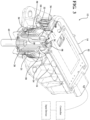
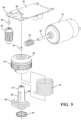
- FIGS 1-3 show various perspective views of the actuator assembly 12.
- the actuator assembly 12 includes a support 14 shown as a housing.
- the support may include a base and a cover.
- the actuator assembly 12 may be configured to be operatively connected with a dog clutch 68 within a gear assembly 64.
- dog clutch 68 refers to a dog clutch and a sleeve connected to the dog clutch.
- the sleeve may be integrated with the dog clutch 68 and the engagement mechanism 60 may be directly connected with the dog clutch sleeve.
- the actuator assembly 12 may be directly coupled with the dog clutch 68.
- the actuator assembly 12 may be coupled with the dog clutch 68 through an engagement mechanism 60.
- the shift assembly 20 may be completely housed within the support 14 of the actuator assembly 12, separate from the engagement mechanism 60 and/or the gear assembly 64.
- the support 14 may be configured as a base which the motor 16, the shift assembly 20, or both are mounted to.
- the actuator assembly 12 includes a shift assembly 20.
- the shift assembly 20 may function to move between a decoupled position 40, an intermediate position 42, and a coupled position 44, operatively coupled with and configured to move a dog clutch 68 from a disengaged position to an engaged position.
- the shift assembly 20 may function to rotate an output member 28, which may be configured to rotate a portion of an engagement mechanism 60 to translate rotational movement into linear movement within a gear assembly 64, moving a dog clutch 68 between positions.
- the shift assembly 20 may function to assist in overcoming a blockage condition caused by an interference between a dog clutch 68 and a receiving gear 70.
- the shift assembly 20 is configured to transition to and from the decoupled position 40 and the coupled position 44 through a plurality of intermediate positions 42, however, for purposes of this application "intermediate position" encompasses the plurality of possible positions between the decoupled position 40 and the coupled position 44.
- the coupled position 44 of the shift assembly 20 corresponds with the engaged position of the dog clutch 68
- the decoupled position 40 corresponds with the disengaged position of the dog clutch 68.
- the shift assembly 20 may include an actuator gear (also known as gear) 22, an input member 24, an actuator output member 28, and a biasing member 21.
- the shift assembly 20 may be connected with the motor 16 through output 18 of the motor 16.
- the motor 16 may function to receive power from a controller 52 to actuate the shift assembly 20 to move between positions 40, 44.
- the actuator assembly 12 may be connected with controller 52.
- the motor 16 may function to provide rotational power to the shift assembly 20.
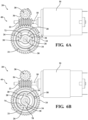
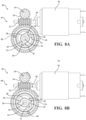
- the output member 18 of the motor 16 is connected with actuator gear 22, such that when the motor 16 is actuated, the actuator gear 22 will spin, turning the input member 24 from a first position 72 to a second position 74 (additionally, see Figures 6A and 6B ).
- the output 18 of the motor 16 may have any suitable size or shape to connect with the shift assembly 20.
- the output 18 may be a shaft, an axle, a coupler, or the like, which is received by the shift assembly 20.
- the motor 16 may receive an actuation power from a controller 52, which actuates the motor 16, rotating the output 18 connected to the actuator gear 22, so that the actuator gear 22 rotates the input member 24 and the actuator output member 28.
- the input member 24 when the input member 24 is rotated in a first direction between the first position 72 and the second position 74, but there is a blockage condition caused by an interference, the input member 24 further tensions the biasing member 21 which provides additional rotational force to the actuator output member 28 to transition the engagement mechanism 60/dog clutch 68 between positions.
- the motor 16 rotates the input member 24 in the first direction to rotate the actuator output member 28, transitioning the shift assembly 20 from the decoupled position 40 to the coupled position 44.
- the actuator assembly 12 includes a motor 16 and an output 18.
- the motor 16 may function to rotate the output 18, driving the actuator gear 22 of the shift assembly 20.
- the motor 16 may function to receive power to rotate clockwise or counterclockwise depending on the movement required to move the shift assembly 20 between positions 40, 42, 44 of the shift assembly 20.
- the motor may be mounted to the housing 14.
- the motor 16 is an electric motor.
- the motor 16 may include a gear set, such as a planetary gear set, which may function to amplify torque generated by the motor 16 to increase the force and/or speed of the motor 16.
- the shift assembly 20 includes an actuator gear 22 connected with the output 18 of the motor 16.
- the actuator gear 22 may function to rotate the input member 24 and a motor sensor gear 36 when the motor 16 is actuated.
- the actuator gear 22 may be any suitable gear design for rotating a complimentary gear.
- some non-limiting examples of the actuator gear 22 may be a spur gear, a helical gear, a double helical gear, a worm gear, or the like.
- the actuator gear 22, as shown in Figures 2-5 is a worm gear, however, alternative configurations are contemplated.
- the actuator gear 22 may be non-backdrivable.
- the actuator gear 22 is configured to rotate when the motor 16 is actuated, turning the input member 24 (and motor sensor gear 36) between positions 72, 74 to move the shift assembly between the decoupled position 40 and coupled position 44.
- the shift assembly 20 includes an input member 24 operatively connected with the actuator gear 22.
- the input member 24 may function to assist in turning the actuator output member 28.
- the input member 24 may function to assist in loading tension into the biasing member 21.
- the input member 24 may be a complimentary geared wheel to be rotated by the actuator gear 22.
- the input member may have any suitable gear design for being rotated by the actuator gear 22.
- some non-limiting examples of the input member 24 gear design may be a track gear, a spur gear, a helical gear, a double helical gear, a worm gear, or the like.
- the input member 24 is configured as a worm wheel.
- the input member 24 may be configured to rotate a predetermined distance between the decoupled position 40 and the coupled position 44.
- the predetermined distance may correspond to the rotational distance (i.e. angle of rotation corresponding to a distance) to move the shift assembly 20 between the decoupled position 40 and the coupled position 44, corresponding to a stroke length.
- the stroke length may be related to moving the dog clutch 68 between a disengaged position and an engaged position with the receiving gear 70.
- the input member 24 and the output member 28 maintain a pre-loaded force on the biasing member 21. Further, as the input member 24 is turned in the first direction from the first position 72 to the second position 74 relative to the output member 28 during a blocked condition causing an additional amount of force to be loaded into the biasing member.
- the predetermined distance of rotation and/or the predetermined load placed on the biasing member 21 may correspond to the stroke length of the engagement mechanism 60.
- the input member 24 is rotated a specific distance required to move the actuator output member 28 and the shift member 62 of the engagement mechanism 60 connected with dog clutch 68 from position to position.
- the input member 24 will turn, and subsequently tension the biasing member 21 about the actuator output member 28, loading a force into the biasing member 21 to allow the actuator output member 28 to quickly and forcefully rotate when the blockage condition (corresponding to intermediate position 42) is removed, causing the dog clutch 68 to deeply and fully engage the receiving gear 70.
- the input member 24 includes a biasing member mount 50 where one end of the biasing member 21 is connected with the input member 24.
- the input member 24 includes one or more tabs 26 for assisting in holding the shift assembly 20 in the decoupled position 40 and in turning the shift assembly 20 from the coupled position 44 back to the decoupled position 40, described further below.
- the shift assembly 20 includes an actuator output member 28 (also referred to as output member) operatively connected with the input member 24.
- the actuator output member 28 may function to rotate when the input member 24 and biasing member 21 are rotated.
- the actuator output member 28 may convert rotational movement of the motor 16 into a rotational output configured to move the engagement mechanism 60 between positions.
- the actuator output member 28 may function to receive a shift member 62 of an engagement mechanism 60 connected with a gear assembly 64, the engagement mechanism 60 converting the rotational output of the actuator output member 28 through the shift member 62 into linear movement within the gear assembly 64.
- the actuator output member 28 may be configured to be disposed axially within an opening of the input member 24 and the biasing member 21.
- the actuator output member 28 may be operatively coupled with the input member 24 through the biasing member.
- the actuator output member 28 member includes a biasing member mount 48 for connecting with the biasing member 21.
- the actuator output includes one or more stops 30 for pre-tensioning the biasing member 21 and assisting in moving the shift assembly 20 from the coupled position 44 back to the decoupled position 40, described further below.
- An O-ring 46 is disposed between the output member 28 and the support 14.
- the shift assembly 20 includes a biasing member 21 operatively coupling the input member 24 and the actuator output member 28.
- the biasing member 21 may function to assist the shift assembly 20 in rapidly moving the output member 28 between the disengaged position 76 and the engaged position 78.
- the biasing member 21 may be configured to function to assist the engagement mechanism 60 in overcoming a momentary blockage condition by storing potential energy in the biasing member 21 when tensioned and releasing that energy as a force onto the actuator output member 28 ( Figures 7A-7D ), operatively connected with the engagement mechanism 60.
- the biasing member 21 is a torsion spring.
- the biasing member 21 has a pre-loaded force and may be configured to have a length in an expanded state configured to rotate the actuator output member 28 through a full engagement rotation.
- the pre-loaded biasing member 21 may be slightly tensioned. Throughout the present application "expanded” refers to the biasing member 21 in a state of substantial expansion, encompassing the slight tension of a preload.
- the biasing member is preloaded in the shift assembly 20 to transition the dog clutch 68 between positions when there are no blockages, however, the biasing member is arranged to allow the input member 24 to turn, even when there is a blockage preventing actuator output member 28 from rotating.
- the tabs 26 and the stops 30 hold the biasing member 21 and the input member 24 in the preloaded state.
- the actuator output member 28 When the blockage condition is present, and the input member 24 has rotated from the first position 72 to the second position 74, the actuator output member 28 is in the disengaged position 76. In disengaged position 76, the actuator output member 28 may be prevented from rotating, and the biasing member 21 stores additional rotational energy of the motor 16 provided by the rotation of the input member 24. The additional stored force in the biasing member 21 is applied by the actuator output member 28 into a consistent force to rotate the shift assembly 20 between the decoupled position 40 and the coupled position 44 as the blockage condition is cleared, moving the output member 28 from the disengaged position 76 to the engaged position 78.
- the biasing member 21 may be configured to generate a substantial force to assist in the alignment and engagement of a dog clutch 68 with a receiving gear 70.
- the application of force by the biasing member 21 onto the actuator output member 28 may be configured to move the engagement mechanism 60 between the disengaged position and the engaged position, providing sufficient force to drive the dog clutch 68 into deep engagement with a receiving gear 70 quickly, when the blockage condition is cleared.
- the biasing member 21 may be configured to have a length that corresponds with the distance the actuator output member 28 must move to transition between the disengaged position 76 and the engaged position 78, to move the actuator assembly from the decoupled position 40 to the coupled position 44, moving the engagement mechanism 60 between the disengaged position and the engaged position.
- the length of biasing member 21 corresponds with the application based on the distance required to move between positions 40, 44.
- the biasing member 21 provides a persistent application force applied through the input member 24 and actuator output member 28 during rotation.
- tabs 26 of the input member 24 and stops 30 of the output member 28 are used to hold the biasing member 21 and the shift assembly 20 in a preloaded state in the decoupled position 40.
- the biasing member 21 is preloaded between the input member 24 and the actuator output member 28, the tabs 26 and stops 30 are configured to hold the preloaded force of the biasing member 21 such that the tabs 26 are pushing against the stops 30.
- the input member 24 turns in the first direction from the first position 72 to the second position 74, the pressure steadily increases as the biasing member 21 is further rotated, applying additional pressure against the actuator output member 28 as biasing member 21 is compressed when there is a blockage condition.
- the actuator assembly 12 may include one or more position sensors.
- the actuator assembly 12 may include a plurality of position sensors.
- the position sensor may be located on or adjacent to the motor 16, input member 24, the housing 14, actuator output member 28, a combination thereof, or any location on or within the actuator assembly 12.
- the position sensor may function to sense a blockage condition by monitoring the position of the motor 16, the input member 24, actuator output member 28, the biasing member 21, the like, or a combination thereof.
- the actuator assembly 12 includes a controller 52 which may be configured to as a part of a position sensor, a part of a motor sensor, or both.
- Each sensor includes an emitter 34, 38 and receiver 56, 58.
- the emitter 34, 38 may be an active emitter or a passive emitter.
- the emitter 34, 38 is magnet, such as shown in Figures 4A-9 .
- the receiver 56, 58 may be configured to sense the position of the emitter 34, 38.
- the receiver 56, 58 is part of the controller 52 and may be configured to sense the change in magnetic field as the emitters 34, 38 are moved, respectively.
- Other methods of sensing are contemplated such as optical, radio, electromagnetic, the like, or a combination thereof.
- the actuator assembly 12 may include a motor sensor.
- the motor sensor may function to signal the position of the motor 16 between the first position 72 and the second position 74 of the input member 24, and the decoupled position 40 and coupled position 44 to the controller 52.
- the motor sensor may include a motor sensor gear 36 which may be configured as a complimentary gear to the actuator gear 22.
- the actuator gear 22 is rotated between positions 72, 74, which turns the motor sensor gear 36, which rotates emitter 38 between the positions 72, 74.
- the receiver 56 determines the position of the emitter 38 and sends a signal to the controller 52 to indicate the position of the motor 16 relative to the position of the actuator output member 28, which is described further below.
- the motor sensor gear 36 may be configured to rotate more rotational degrees than the input member 24 transitioning between positions 72, 74 as the motor 16 rotates. By placing the emitter 38 onto the motor sensor gear 36 that is configured to rotate more than the input member 24, the controller 52 may more accurately determine the position of the input member 24. In some examples, the motor sensor gear 36 may rotate two or more times than the input member 24 when the input member 24 is moved between the first position 72 and the second position 74. For examples, the input member 24 may rotate 40 degrees and the motor sensor gear 36 may rotate 80 degrees.
- the motor sensor gear 36 and emitter 38 are rotated more rotational degrees than the input member 24, allowing the receiver56 to sense the emitter 38 more than once, decreasing the effect of tolerance deviations and errors between the receiver 56 and the emitter 38 regarding the position of the input member 24.
- tolerance deviations and errors may be free play of the actuator gear 22, input member 24, motor sensor gear 36, or a combination thereof.
- Other sources of error and/or positional deviation may be assembly variation of the emitter 38, the receiver56, the motor sensor gear 36, or a combination thereof.
- Other examples of deviation and error are also considered.
- the motor sensor gear 36 may be configured to rotated three times more than input member 24 while the input member 24 is moved between positions 72, 74 (e.g.
- the input member 24 rotates 100 degrees, motor sensor gear rotates 300 degrees).
- the motor sensor gear 36 is rotating more rotational degrees than the input member 24 during every transition, tolerance deviations and sensing errors of the actuator gear 22, emitter 38, motor sensor gear 36, and the receiver56 are distributed over the additional degrees of rotation, allowing the tolerance deviations and error to be mitigated by a factor greater than one, allowing the controller 52 to more accurately determine the position of the input member 24.
- the input member 24 may rotate 100 degrees between positions 72, 74 while the motor sensor gear 36 and emitter 38 may complete 200 degrees of rotation, allowing the sensing device 56 at least twice as many sensing positions than if the emitter was located on the input member 24.
- the deviation is distributed by a factor greater than one.
- the actuator assembly 12 may include a shift sensor.
- the shift sensor may function to signal the position of the actuator output member 28 between the disengaged position 76 and the engaged position 78 to the controller 52.
- the shift sensor may be configured as a emitter 34 located on the actuator output member 28 and a receiver58.
- Figure 4A depicts the emitter 34 as a magnet on the actuator output member 28.
- the actuator output member 28 rotates as the input member 24 is turned, resulting in the emitter 34 being rotated between the disengaged position 76 and the engaged position 78, and sending a signal to the controller 52 to indicate the position of the actuator output member 28.
- the motor 16 turns the input member 24 from the first position 72 to the second position 74, but the actuator output member 28 does not move or only partially moves.
- the shift assembly 20 is in the intermediate position 42 ( Figure 7B ).
- the emitter 34 of shift sensor sends a signal through the receiver58 on the controller 52, along with the signal from receiver56, indicating that shift assembly 20 is in the intermediate position 42, since the motor 16 has moved the input member 24 but the actuator output member 28 has remained stationary.
- the shift assembly 20 may function to assist the actuator output member 28 in transitioning between the disengaged position 76 and the engaged position 78, which in turn transitions the shift assembly 20 between the decoupled position 40 and the coupled position 44. While moving from the decoupled position 40 to the coupled position 44, when there is a dog-clutch misalignment causing a blockage condition, the shift assembly 20 applies a force F and/or torque through the actuator output member 28 against the shift member 62 of the engagement mechanism 60 ( Figure 7B ).
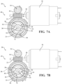
- Figures 7A-7D illustrate a schematic view of the actuator assembly 12 moving from the decoupled position 40 (7A), through an intermediate position 42 when a blockage condition is present (7B, 7C), into a coupled position 44 (7D).
- the biasing member 21 is loaded to apply force F onto the actuator output member 28 to apply sufficient force to the engagement mechanism 60 to quickly move the dog clutch 68 into the engaged position during the short time window when the teeth of the receiving gear 70 and teeth of the dog clutch 68 are aligned.
- the force F is released during the alignment window, rotating the actuator output member 28 from the disengaged position 76 toward the engaged position 78 (as seen in Figure 7C ) transitioning the shift assembly 20 from the intermediate position 42 into the coupled position 44.
- the biasing member 21 is configured with a rotational length long enough to rotate the actuator output member 28 the entire stroke required to move the dog clutch 68 between the disengaged position and the engaged position with the receiving gear, transmitting the velocity and torque to and from the receiving gear 70 and the dog clutch 68, causing both receiving gear 70 and dog clutch 68 to rotate at the same speed.
- the output member 28 is in the engaged position 78 and the emitter 34 of the actuator output sensor has been rotated, signaling to the controller 52 that the actuator output member 28 has successfully engaged the dog clutch 68 with the receiving gear 70, and, additionally how successfully the engagement is (e.g. depth of engagement) and when torque may be applied.
- the intermediate position 42 occurs when a blockage condition, such as when there is a misalignment between teeth of the dog clutch gear 68 and the receiving gear 70 causing an interference.
- a blockage condition such as when there is a misalignment between teeth of the dog clutch gear 68 and the receiving gear 70 causing an interference.
- the resistive force 54 is applied to actuator output member 28 when the actuator assembly 12 is moving between the decoupled position 40 and the coupled position 44.
- the blockage is caused by a momentary misalignment of the dog clutch 68 with the receiving gear 70, so during this misalignment, the engagement mechanism 60 is pressing against the dog clutch 68 which is pressing against the receiving gear 70.
- the force 54 is translated through the actuator output member 28 through the biasing member to the input member 24.
- the stored energy of the biasing member 21 is applied to the actuator output member 28, which may then be applied onto a shift member 62 of the engagement mechanism 60, the dog clutch 68, or both.
- the momentary misalignment/blockage is cleared, the stored energy released and translated into a movement force, rotating the actuator output member 28 from the disengaged position 76 to the engaged position 78 through the desired rotational distance, placing the shift assembly 20 into the coupled position 44 (see Figures 6B and 7D ).
- the intermediate position 42 may be present going to coupled position 44 from the decoupled position 40. Once in the coupled position 44, the additional tension on the biasing member 21from the intermediate position 42 is released and the biasing member 21 is applying the pre-loaded force onto the output member 28.
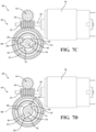
- FIGs 8A and 8B schematically illustrating moving the actuator assembly 12 from the coupled position 44 back to the decoupled position 40.
- the motor 16 is actuated in the opposite direction, rotating the actuator gear 22, which turns input member 24 and the motor sensor gear 36 in a second direction.
- the tabs 26 on the input member 24 rotate about the output member 28.
- the tabs 26 then push against the stops 30, rotating the output member 28 in the second direction back into the first position 72 and disengaged position 76, respectively ( Figure 8B ).
- the biasing member 21 does not build tension, but rather stays in the preloaded state.
Landscapes
- Engineering & Computer Science (AREA)
- General Engineering & Computer Science (AREA)
- Mechanical Engineering (AREA)
- Gear-Shifting Mechanisms (AREA)
Claims (15)
- Aktuatoraufbau (12) mit:einem Träger (14),einem Motor (16), der mit dem Träger (14) verbunden ist,einem Schaltaufbau (20), der betriebsmäßig mit dem Motor (16) verbunden ist, um sich zwischen einer entkoppelten Stellung (40) und einer gekoppelten Stellung (44) mit einer Mehrzahl von Zwischenstellungen (42) zwischen der entkoppelten Stellung und der gekoppelten Stellung zu bewegen, wobei der Schaltaufbau (20) aufweist:ein Zahnrad (22), das mit dem Motor (16) verbunden ist,ein Eingangsteil (24), das in Verbindung mit dem Zahnrad (22) steht, wobei das Eingangsteil (24) einen Vorsprung (26) hat, wobei das Eingangsteil dazu ausgestaltet ist, zwischen einer ersten Stellung (72) und einer zweiten Stellung (74) überzugehen, wobei das Eingangsteil (24) in der ersten Stellung (72) ist, wenn der Schaltaufbau in der entkoppelten Stellung (40) ist,ein Ausgangsteil (28) mit einem Anschlag (30), wobei das Ausgangsteil betriebsmäßig mit dem Eingangsteil (24) verbunden ist und dazu ausgestaltet ist, sich über eine Winkeldistanz zu bewegen, die einen Hubweg zwischen einer gelösten Stellung und einer Eingriffsstellung definiert, wobei das Ausgangsteil (28) in der gelösten Stellung ist, wenn der Schaltaufbau (20) in der entkoppelten Stellung (20) ist, undein Vorspannelement (21), das das Eingangsteil (24) mit dem Ausgangsteil verbindet, wobei das Vorspannelement (21) in einem vorgespannten Zustand gehalten ist, wenn das Eingangsteil (24) in der ersten Stellung (72) und das Ausgangsteil (28) in der gelösten Stellung ist, so dass der Anschlag (30) des Ausgangsteils (28) an dem Vorsprung (26) des Eingangsteils (24) anliegt,wobei das Eingangsteil (24) sich in einer ersten Richtung aus der ersten Stellung (72) in die zweite Stellung (74) relativ zum Ausgangsteil (28) dreht, was den Vorsprung (26) des Eingangsteils (24) von dem Anschlag (30) des Ausgangsteils (28) trennt und eine Spannung des Vorspannelements (21) zwischen dem Eingangsteil (24) und dem Ausgangsteil (28) erhöht, und das Ausgangsteil (28) aufgrund einer einen blockierten Zustand verursachenden Störung in der gelösten Stellung bleibt, undwobei das Vorspannelement (21) in einem Freigabezustand auf das Verschwinden der Störung hin das Ausgangsteil (28) in die erste Richtung relativ zum Eingangsteil (24) dreht, so dass das Ausgangsteil (28) sich über die Winkeldistanz aus der gelösten Stellung in die Eingriffsstellung dreht, was den Anschlag (30) des Ausgangsteils (28) wieder mit dem Vorsprung (26) des Eingangsteils (24) in Eingriff bringt, während das Eingangsteil (24) in der zweiten Stellung (74) verbleibt, um den Schaltaufbau in die gekoppelte Stellung (44) zu bringen.
- Aktuatoraufbau (12) nach Anspruch 1, wobei das Vorspannelement (21) ein Vorspannelement mit einem ersten Ende und einem zweiten Ende ist, wobei das erste Ende des Vorspannelements (21) mit dem Eingangsteil (24) verbunden ist und das zweite Ende des Vorspannelements (21) mit dem Ausgangsteil (28) verbunden ist.
- Aktuatoraufbau (12) nach Anspruch 2, wobei wenigstens ein Bereich des Eingangsteils (24) eine Öffnung aufweist und die Öffnung wenigstens einen Teil des Ausgangsteils (28) umgibt.
- Aktuatoraufbau (12) nach Anspruch 3, wobei der Vorsprung (26) in die Öffnung des Eingangsteils (24) vorsteht und der Anschlag (30) von dem Ausgangsteil (28) ausgeht, wobei der Anschlag (30) und der Vorsprung (26) komplementäre Formen haben.
- Aktuatoraufbau (12) nach Anspruch 4, wobei das Vorspannelement (21) in der gelösten Stellung vorgespannt ist, indem das Vorspannelement (21) eine Vorspannkraft auf eine Basisträgerhalterung des Eingangsteils (24) und auf ein Basisteil an dem Ausgangsteil (28) ausübt, was bewirkt, dass der Vorsprung (26) des Eingangsteils (24) und der Anschlag (30) des Ausgangsteils (28) die Vorspannkraft aufeinander ausüben.
- Aktuatoraufbau (12) nach Anspruch 5, wobei das Ausgangsteil (28) durch das Eingangsteil (24) aus der gelösten Stellung in die Eingriffsstellung bewegt wird, wenn das Eingangsteil (24) in eine zweite Richtung bewegt wird, was das Eingangsteil (24) aus der zweiten Stellung (74) in die erste Stellung (72) bewegt und bewirkt, dass der Vorsprung des Eingangsteils (24) in Anlage an den Anschlag (30) des Ausgangsteils (28) kommt und das Ausgangsteil (28) und das Eingangsteil (24) sich zusammen in die zweite Richtung drehen, was den Aktuatoraufbau zurück in die entkoppelte Stellung (40) bringt.
- Aktuatoraufbau (12) nach Anspruch 1, der ferner eine Steuereinheit in Kommunikation mit dem Motor (16) und einen Sensor in Kommunikation mit der Steuereinheit (52) aufweist, wobei die Steuereinheit (52) dazu eingerichtet ist, den Motor (16) zu betätigen und die Stellung des Schaltaufbaus (20) zu bestimmen.
- Aktuatoraufbau (12) nach Anspruch 7, wobei der Sensor einen Sender (34, 38) und einen Empfänger (56, 58) aufweist, wobei einer von dem Sender (34, 38) und dem Empfänger betriebsmäßig mit dem Ausgangsteil (28) und der andere von dem Sender und dem Empfänger betriebsmäßig mit der Steuereinheit (52) verbunden ist.
- Aktuatoraufbau (12) nach Anspruch 8, der ferner ein Sensorzahnrad (36) in Verbindung mit dem Zahnrad (22) aufweist, wobei das Sensorzahnrad (36) einen Sender (38) und einen Empfänger (56) hat, wobei einer von dem Sender und dem Empfänger betriebsmäßig mit dem Sensorzahnrad (36) und der andere von dem Sender und dem Empfänger betriebsmäßig mit der Steuereinheit (52) verbunden ist.
- Aktuatoraufbau (12) nach Anspruch 9, wobei das Sensorzahnrad (36) und das Eingangsteil (24) beide gedreht werden, wenn der Motor (16) eingeschaltet ist.
- Aktuatoraufbau (12) nach Anspruch 8, wobei der mit dem Ausgangsteil (28) in Verbindung stehende Sender (34) bewegt wird, wenn das Ausgangsteil (28) bewegt wird, und die Steuereinheit (52) dazu eingerichtet ist, um festzustellen, ob das Ausgangsteil (28) in der gelösten Stellung oder in der Eingriffsstellung ist, indem der Sender (34) an dem Ausgangsteil (28) relativ zur Position des Sensorzahnrads (36) überwacht wird.
- Verfahren zum Betreiben des Aktuatoraufbaus (12) nach Anspruch 1, wobei das Verfahren die Schritte aufweist:Betätigen des Motors (16) in eine erste Richtung, um das Zahnrad (22) zu drehen und das Eingangsteil (24) aus der ersten Stellung (72) in die zweite Stellung (74) zu drehen, Erhöhen der Spannung des Vorspannelements (21) zwischen dem Eingangsteil (24) und dem Ausgangsteil (28), was den Vorsprung (26) des Eingangsteils (24) vom Anschlag (30) des Ausgangsteils (28) entfernt, wenn das Ausgangsteil (28) in der gelösten Stellung bleibt, wenn eine einen Blockadezustand verursachende Störung vorliegt,Aufhebung des Blockadezustands,Abbau der Spannung des Vorspannelements (21) und Drehen des Ausgangsteils (28) über die Winkeldistanz aus der gelösten Stellung in die Eingriffsstellung in die erste Richtung,Wieder-Ineingriffbringen des Anschlags (30) des Ausgangsteils (28) mit dem Vorsprung des Eingangsteils (24), während das Eingangsteil (24) in der zweiten Stellung (74) bleibt, um den Schaltaufbau in die gekoppelte Stellung (44) zu bringen.
- Verfahren nach Anspruch 12, das weiter die Schritte aufweist:Bewegen des Eingangsteils (24) in die zweite Richtung aus der zweiten Stellung (24) zu der ersten Stellung (72) hin,Ineingriffbringen des Vorsprungs (26) des Eingangsteils (24) mit dem Anschlag (30) des Ausgangsteils (28),Drehen des Ausgangsteils (28) mit dem Eingangsteil (24) in die zweite Richtung, um das Ausgangsteil (28) aus der Eingriffsstellung in die gelöste Stellung zu bewegen, und Drehen des Ausgangsteils (28) und des Eingangsteils (24) zusammen in die zweite Richtung, was den Aktuatoraufbau in die entkoppelte Stellung (40) bringt.
- Verfahren nach Anspruch 12, wobei der Aktuatoraufbau (12) ferner eine Steuereinheit (52), die in Verbindung mit dem Motor (16) steht, und einen Sensor aufweist, der in Verbindung mit der Steuereinheit (52) steht, wobei die Steuereinheit dazu eingerichtet ist, den Motor (16) zu betätigen und die Stellung des Schaltaufbaus (12) zu bestimmen, und wobei der Sensor einen Sender (34) und einen Empfänger (55) aufweist, wobei der Sender (34) betriebsmäßig mit dem Ausgangsteil (28) verbunden ist und der Empfänger (58) betriebsmäßig mit der Steuereinheit (52) verbunden ist, und wobei das Verfahren weiterhin die Schritte aufweist:Drehen des Senders (34) mit dem Ausgangsteil (28), wenn das Ausgangsteil (28) aus der gelösten Stellung in die Eingriffsstellung bewegt wird,Überwachen des Winkels der Drehung des Senders (34) an dem Ausgangsteil (28) und aufgrund des Winkels der Drehung des Senders (34) am Ausgangsteil (28) Bestimmen, mit der Steuereinheit (52), ob das Ausgangsteil (28) in der gelösten Stellung oder der Eingriffsstellung ist.
- Verfahren nach Anspruch 12, das ferner ein Sensorzahnrad (34) in Kommunikation mit dem mit dem Motor (16) verbundenen Zahnrad (22) aufweist, wobei das Sensorzahnrad (36) einen Sender (38) und einen Empfänger (56) hat, wobei einer von dem Sender und dem Empfänger betriebsmäßig mit dem Sensorzahnrad (36) verbunden ist und der andere von dem Sender und dem Empfänger betriebsmäßig mit der Steuereinheit (52) verbunden ist, wobei sowohl das Sensorzahnrad (36) als auch das Eingangsteil (24) gedreht werden, wenn der Motor (16) betätigt wird, und wobei das Sensorzahnrad (36) wenigstens um das Dreifache mehr als das Eingangsteil (24) zwischen der ersten Stellung (72) und der zweiten Stellung (74) gedreht wird.
Applications Claiming Priority (2)
| Application Number | Priority Date | Filing Date | Title |
|---|---|---|---|
| US202163197641P | 2021-06-07 | 2021-06-07 | |
| PCT/IB2022/055307 WO2022259155A1 (en) | 2021-06-07 | 2022-06-07 | Rotary decoupling actuator assembly with integrated spring assistance for blocked engagement |
Publications (2)
| Publication Number | Publication Date |
|---|---|
| EP4352384A1 EP4352384A1 (de) | 2024-04-17 |
| EP4352384B1 true EP4352384B1 (de) | 2025-03-26 |
Family
ID=82214143
Family Applications (1)
| Application Number | Title | Priority Date | Filing Date |
|---|---|---|---|
| EP22733739.1A Active EP4352384B1 (de) | 2021-06-07 | 2022-06-07 | Drehentkopplungsaktuatoranordnung mit integrierter federunterstützung für blockierte einrastung |
Country Status (4)
| Country | Link |
|---|---|
| US (1) | US12253164B2 (de) |
| EP (1) | EP4352384B1 (de) |
| CN (1) | CN117529623A (de) |
| WO (1) | WO2022259155A1 (de) |
Family Cites Families (15)
| Publication number | Priority date | Publication date | Assignee | Title |
|---|---|---|---|---|
| JP2003336701A (ja) | 2002-05-22 | 2003-11-28 | Hitachi Ltd | 自動変速機 |
| JP2008256007A (ja) | 2007-04-02 | 2008-10-23 | Toyota Central R&D Labs Inc | ドグクラッチアクチュエータ |
| GB2458790B (en) | 2008-03-31 | 2012-09-19 | Gm Global Tech Operations Inc | Double-clutch transmission for vehicles |
| US8075437B2 (en) | 2008-07-30 | 2011-12-13 | Allison Transmission, Inc. | Gear assembly for multi-speed countershaft transmission |
| EP2886911B1 (de) | 2013-12-20 | 2016-08-03 | BorgWarner Inc. | Federbelastete Schaltaktuatoranordnung mit Haltemechanismus |
| KR20160119790A (ko) | 2014-02-12 | 2016-10-14 | 보그워너 토크트랜스퍼 시스템즈 아베 | 도그 클러치용 액추에이터 및 이의 제어를 위한 방법 |
| DE102014015093B4 (de) | 2014-10-10 | 2022-01-20 | Audi Ag | Klauenkupplung mit Sensor zur Erkennung eines Schließzustands |
| DE102014224366B4 (de) | 2014-11-28 | 2024-11-21 | Schaeffler Technologies AG & Co. KG | Betätigungsanordnung und Verfahren zur Betätigung einer Betätigungsvorrichtung |
| FR3041056B1 (fr) | 2015-09-10 | 2018-11-30 | Renault S.A.S | Procede d'apprentisage de la position neutre d'un actionneur de passage |
| DE112017002133T5 (de) | 2016-04-22 | 2019-05-23 | American Axle & Manufacturing, Inc. | Antriebsstrang-Stellglied, das gespeicherte Energie nutzt, um ein Stellglied-Ausgangselement zu bewegen |
| US10352399B2 (en) | 2016-04-28 | 2019-07-16 | Lear Corporation | Actuator assembly |
| CN208331226U (zh) * | 2016-12-28 | 2019-01-04 | Sl株式会社 | 车辆用变速器控制装置 |
| WO2020046974A1 (en) | 2018-08-27 | 2020-03-05 | Massachusetts Institute Of Technology | Position-based actuated coupling in a mechanical power transmission system |
| US10988022B2 (en) | 2019-02-12 | 2021-04-27 | Borgwarner Inc. | Electro-mechanical on demand (EMOD) transfer case—dual drive gear and shift fork consolidation |
| EP3741634B1 (de) | 2019-05-23 | 2022-07-06 | Robert Bosch GmbH | Verteilte feststellbremssteuerung |
-
2022
- 2022-06-07 US US18/567,196 patent/US12253164B2/en active Active
- 2022-06-07 EP EP22733739.1A patent/EP4352384B1/de active Active
- 2022-06-07 WO PCT/IB2022/055307 patent/WO2022259155A1/en not_active Ceased
- 2022-06-07 CN CN202280040971.1A patent/CN117529623A/zh active Pending
Also Published As
| Publication number | Publication date |
|---|---|
| US12253164B2 (en) | 2025-03-18 |
| EP4352384A1 (de) | 2024-04-17 |
| WO2022259155A1 (en) | 2022-12-15 |
| CN117529623A (zh) | 2024-02-06 |
| US20240288064A1 (en) | 2024-08-29 |
Similar Documents
| Publication | Publication Date | Title |
|---|---|---|
| JP5440862B2 (ja) | 変速装置 | |
| US9272690B2 (en) | Parking lock arrangement | |
| US10113636B2 (en) | Power actuator with integral decoupling mechanism | |
| US10539235B2 (en) | Internal electronic park actuator | |
| EP3622204B1 (de) | Linearantrieb mit sicherheitsmechanismus | |
| CN104254456B (zh) | 分动箱链轮空转齿轮致动 | |
| US20120279823A1 (en) | Parking interlock arrangement for an automatic transmission | |
| US10900565B2 (en) | Lost motion transmission shifter | |
| US9194485B2 (en) | Shift system for power transfer unit having dual sector shift actuator | |
| US6065581A (en) | Camming manual lever for pull-out load | |
| EP4352384B1 (de) | Drehentkopplungsaktuatoranordnung mit integrierter federunterstützung für blockierte einrastung | |
| WO2017129610A2 (en) | Clutch actuator for a vehicle | |
| EP2878860A1 (de) | Parksperranordnung und Getriebe für ein Fahrzeug | |
| US12203545B2 (en) | External actuator system | |
| EP2372199B1 (de) | Automatisiertes Handschaltgetriebe mit Parksperre | |
| ES2981391T3 (es) | Unidad de transmisión para vehículos de motor con marcha atrás y vehículo de motor que comprende la unidad de transmisión | |
| KR20250090669A (ko) | 차량용 차동잠금장치 | |
| EP2596998B1 (de) | Vorrichtung zum Sperren eines Fahrzeuggetriebes in einer Parkstellung | |
| FR2948161A1 (fr) | Procede de commande et actionneur electromecanique pour boite de vitesses |
Legal Events
| Date | Code | Title | Description |
|---|---|---|---|
| STAA | Information on the status of an ep patent application or granted ep patent |
Free format text: STATUS: UNKNOWN |
|
| STAA | Information on the status of an ep patent application or granted ep patent |
Free format text: STATUS: THE INTERNATIONAL PUBLICATION HAS BEEN MADE |
|
| PUAI | Public reference made under article 153(3) epc to a published international application that has entered the european phase |
Free format text: ORIGINAL CODE: 0009012 |
|
| STAA | Information on the status of an ep patent application or granted ep patent |
Free format text: STATUS: REQUEST FOR EXAMINATION WAS MADE |
|
| 17P | Request for examination filed |
Effective date: 20231208 |
|
| AK | Designated contracting states |
Kind code of ref document: A1 Designated state(s): AL AT BE BG CH CY CZ DE DK EE ES FI FR GB GR HR HU IE IS IT LI LT LU LV MC MK MT NL NO PL PT RO RS SE SI SK SM TR |
|
| DAV | Request for validation of the european patent (deleted) | ||
| DAX | Request for extension of the european patent (deleted) | ||
| GRAP | Despatch of communication of intention to grant a patent |
Free format text: ORIGINAL CODE: EPIDOSNIGR1 |
|
| STAA | Information on the status of an ep patent application or granted ep patent |
Free format text: STATUS: GRANT OF PATENT IS INTENDED |
|
| GRAS | Grant fee paid |
Free format text: ORIGINAL CODE: EPIDOSNIGR3 |
|
| GRAA | (expected) grant |
Free format text: ORIGINAL CODE: 0009210 |
|
| STAA | Information on the status of an ep patent application or granted ep patent |
Free format text: STATUS: THE PATENT HAS BEEN GRANTED |
|
| INTG | Intention to grant announced |
Effective date: 20250127 |
|
| AK | Designated contracting states |
Kind code of ref document: B1 Designated state(s): AL AT BE BG CH CY CZ DE DK EE ES FI FR GB GR HR HU IE IS IT LI LT LU LV MC MK MT NL NO PL PT RO RS SE SI SK SM TR |
|
| REG | Reference to a national code |
Ref country code: GB Ref legal event code: FG4D |
|
| REG | Reference to a national code |
Ref country code: CH Ref legal event code: EP |
|
| REG | Reference to a national code |
Ref country code: DE Ref legal event code: R096 Ref document number: 602022012312 Country of ref document: DE |
|
| REG | Reference to a national code |
Ref country code: IE Ref legal event code: FG4D |
|
| RAP2 | Party data changed (patent owner data changed or rights of a patent transferred) |
Owner name: KONGSBERG AUTOMOTIVE HOLDING 2 AS |
|
| PG25 | Lapsed in a contracting state [announced via postgrant information from national office to epo] |
Ref country code: RS Free format text: LAPSE BECAUSE OF FAILURE TO SUBMIT A TRANSLATION OF THE DESCRIPTION OR TO PAY THE FEE WITHIN THE PRESCRIBED TIME-LIMIT Effective date: 20250626 |
|
| PG25 | Lapsed in a contracting state [announced via postgrant information from national office to epo] |
Ref country code: FI Free format text: LAPSE BECAUSE OF FAILURE TO SUBMIT A TRANSLATION OF THE DESCRIPTION OR TO PAY THE FEE WITHIN THE PRESCRIBED TIME-LIMIT Effective date: 20250326 |
|
| PGFP | Annual fee paid to national office [announced via postgrant information from national office to epo] |
Ref country code: DE Payment date: 20250507 Year of fee payment: 4 |
|
| REG | Reference to a national code |
Ref country code: LT Ref legal event code: MG9D |
|
| PG25 | Lapsed in a contracting state [announced via postgrant information from national office to epo] |
Ref country code: NO Free format text: LAPSE BECAUSE OF FAILURE TO SUBMIT A TRANSLATION OF THE DESCRIPTION OR TO PAY THE FEE WITHIN THE PRESCRIBED TIME-LIMIT Effective date: 20250626 |
|
| PG25 | Lapsed in a contracting state [announced via postgrant information from national office to epo] |
Ref country code: HR Free format text: LAPSE BECAUSE OF FAILURE TO SUBMIT A TRANSLATION OF THE DESCRIPTION OR TO PAY THE FEE WITHIN THE PRESCRIBED TIME-LIMIT Effective date: 20250326 |
|
| PG25 | Lapsed in a contracting state [announced via postgrant information from national office to epo] |
Ref country code: LV Free format text: LAPSE BECAUSE OF FAILURE TO SUBMIT A TRANSLATION OF THE DESCRIPTION OR TO PAY THE FEE WITHIN THE PRESCRIBED TIME-LIMIT Effective date: 20250326 |
|
| PG25 | Lapsed in a contracting state [announced via postgrant information from national office to epo] |
Ref country code: GR Free format text: LAPSE BECAUSE OF FAILURE TO SUBMIT A TRANSLATION OF THE DESCRIPTION OR TO PAY THE FEE WITHIN THE PRESCRIBED TIME-LIMIT Effective date: 20250627 Ref country code: BG Free format text: LAPSE BECAUSE OF FAILURE TO SUBMIT A TRANSLATION OF THE DESCRIPTION OR TO PAY THE FEE WITHIN THE PRESCRIBED TIME-LIMIT Effective date: 20250326 |
|
| PGFP | Annual fee paid to national office [announced via postgrant information from national office to epo] |
Ref country code: AT Payment date: 20250721 Year of fee payment: 4 |
|
| REG | Reference to a national code |
Ref country code: NL Ref legal event code: MP Effective date: 20250326 |
|
| PG25 | Lapsed in a contracting state [announced via postgrant information from national office to epo] |
Ref country code: NL Free format text: LAPSE BECAUSE OF FAILURE TO SUBMIT A TRANSLATION OF THE DESCRIPTION OR TO PAY THE FEE WITHIN THE PRESCRIBED TIME-LIMIT Effective date: 20250326 |
|
| PG25 | Lapsed in a contracting state [announced via postgrant information from national office to epo] |
Ref country code: SE Free format text: LAPSE BECAUSE OF FAILURE TO SUBMIT A TRANSLATION OF THE DESCRIPTION OR TO PAY THE FEE WITHIN THE PRESCRIBED TIME-LIMIT Effective date: 20250326 |
|
| REG | Reference to a national code |
Ref country code: AT Ref legal event code: MK05 Ref document number: 1779261 Country of ref document: AT Kind code of ref document: T Effective date: 20250326 |
|
| PG25 | Lapsed in a contracting state [announced via postgrant information from national office to epo] |
Ref country code: SM Free format text: LAPSE BECAUSE OF FAILURE TO SUBMIT A TRANSLATION OF THE DESCRIPTION OR TO PAY THE FEE WITHIN THE PRESCRIBED TIME-LIMIT Effective date: 20250326 |
|
| PG25 | Lapsed in a contracting state [announced via postgrant information from national office to epo] |
Ref country code: PT Free format text: LAPSE BECAUSE OF FAILURE TO SUBMIT A TRANSLATION OF THE DESCRIPTION OR TO PAY THE FEE WITHIN THE PRESCRIBED TIME-LIMIT Effective date: 20250728 Ref country code: ES Free format text: LAPSE BECAUSE OF FAILURE TO SUBMIT A TRANSLATION OF THE DESCRIPTION OR TO PAY THE FEE WITHIN THE PRESCRIBED TIME-LIMIT Effective date: 20250326 |
|
| REG | Reference to a national code |
Ref country code: DE Ref legal event code: R081 Ref document number: 602022012312 Country of ref document: DE Owner name: KONGSBERG AUTOMOTIVE HOLDING 2 AS, NO Free format text: FORMER OWNER: KA GROUP AG, ZUERICH, CH |
|
| PG25 | Lapsed in a contracting state [announced via postgrant information from national office to epo] |
Ref country code: IT Free format text: LAPSE BECAUSE OF FAILURE TO SUBMIT A TRANSLATION OF THE DESCRIPTION OR TO PAY THE FEE WITHIN THE PRESCRIBED TIME-LIMIT Effective date: 20250326 Ref country code: PL Free format text: LAPSE BECAUSE OF FAILURE TO SUBMIT A TRANSLATION OF THE DESCRIPTION OR TO PAY THE FEE WITHIN THE PRESCRIBED TIME-LIMIT Effective date: 20250326 |
|
| PG25 | Lapsed in a contracting state [announced via postgrant information from national office to epo] |
Ref country code: AT Free format text: LAPSE BECAUSE OF FAILURE TO SUBMIT A TRANSLATION OF THE DESCRIPTION OR TO PAY THE FEE WITHIN THE PRESCRIBED TIME-LIMIT Effective date: 20250326 |
|
| PG25 | Lapsed in a contracting state [announced via postgrant information from national office to epo] |
Ref country code: EE Free format text: LAPSE BECAUSE OF FAILURE TO SUBMIT A TRANSLATION OF THE DESCRIPTION OR TO PAY THE FEE WITHIN THE PRESCRIBED TIME-LIMIT Effective date: 20250326 |
|
| PG25 | Lapsed in a contracting state [announced via postgrant information from national office to epo] |
Ref country code: RO Free format text: LAPSE BECAUSE OF FAILURE TO SUBMIT A TRANSLATION OF THE DESCRIPTION OR TO PAY THE FEE WITHIN THE PRESCRIBED TIME-LIMIT Effective date: 20250326 |
|
| PG25 | Lapsed in a contracting state [announced via postgrant information from national office to epo] |
Ref country code: SK Free format text: LAPSE BECAUSE OF FAILURE TO SUBMIT A TRANSLATION OF THE DESCRIPTION OR TO PAY THE FEE WITHIN THE PRESCRIBED TIME-LIMIT Effective date: 20250326 |
|
| PG25 | Lapsed in a contracting state [announced via postgrant information from national office to epo] |
Ref country code: IS Free format text: LAPSE BECAUSE OF FAILURE TO SUBMIT A TRANSLATION OF THE DESCRIPTION OR TO PAY THE FEE WITHIN THE PRESCRIBED TIME-LIMIT Effective date: 20250726 |
|
| REG | Reference to a national code |
Ref country code: DE Ref legal event code: R097 Ref document number: 602022012312 Country of ref document: DE |
|
| PG25 | Lapsed in a contracting state [announced via postgrant information from national office to epo] |
Ref country code: DK Free format text: LAPSE BECAUSE OF FAILURE TO SUBMIT A TRANSLATION OF THE DESCRIPTION OR TO PAY THE FEE WITHIN THE PRESCRIBED TIME-LIMIT Effective date: 20250326 |
|
| PG25 | Lapsed in a contracting state [announced via postgrant information from national office to epo] |
Ref country code: CZ Free format text: LAPSE BECAUSE OF FAILURE TO SUBMIT A TRANSLATION OF THE DESCRIPTION OR TO PAY THE FEE WITHIN THE PRESCRIBED TIME-LIMIT Effective date: 20250326 |
|
| REG | Reference to a national code |
Ref country code: CH Ref legal event code: H13 Free format text: ST27 STATUS EVENT CODE: U-0-0-H10-H13 (AS PROVIDED BY THE NATIONAL OFFICE) Effective date: 20260127 |
|
| PG25 | Lapsed in a contracting state [announced via postgrant information from national office to epo] |
Ref country code: MC Free format text: LAPSE BECAUSE OF FAILURE TO SUBMIT A TRANSLATION OF THE DESCRIPTION OR TO PAY THE FEE WITHIN THE PRESCRIBED TIME-LIMIT Effective date: 20250326 |
|
| PLBE | No opposition filed within time limit |
Free format text: ORIGINAL CODE: 0009261 |
|
| STAA | Information on the status of an ep patent application or granted ep patent |
Free format text: STATUS: NO OPPOSITION FILED WITHIN TIME LIMIT |
|
| REG | Reference to a national code |
Ref country code: CH Ref legal event code: L10 Free format text: ST27 STATUS EVENT CODE: U-0-0-L10-L00 (AS PROVIDED BY THE NATIONAL OFFICE) Effective date: 20260211 |
|
| PG25 | Lapsed in a contracting state [announced via postgrant information from national office to epo] |
Ref country code: LU Free format text: LAPSE BECAUSE OF NON-PAYMENT OF DUE FEES Effective date: 20250607 |
|
| REG | Reference to a national code |
Ref country code: BE Ref legal event code: MM Effective date: 20250630 |
|
| 26N | No opposition filed |
Effective date: 20260105 |
|
| PG25 | Lapsed in a contracting state [announced via postgrant information from national office to epo] |
Ref country code: IE Free format text: LAPSE BECAUSE OF NON-PAYMENT OF DUE FEES Effective date: 20250607 |
|
| PG25 | Lapsed in a contracting state [announced via postgrant information from national office to epo] |
Ref country code: BE Free format text: LAPSE BECAUSE OF NON-PAYMENT OF DUE FEES Effective date: 20250630 |
|
| PG25 | Lapsed in a contracting state [announced via postgrant information from national office to epo] |
Ref country code: FR Free format text: LAPSE BECAUSE OF NON-PAYMENT OF DUE FEES Effective date: 20250630 |