EP4352832B1 - Verriegelungseinrichtung für leitungsverbinder - Google Patents
Verriegelungseinrichtung für leitungsverbinder Download PDFInfo
- Publication number
- EP4352832B1 EP4352832B1 EP22751640.8A EP22751640A EP4352832B1 EP 4352832 B1 EP4352832 B1 EP 4352832B1 EP 22751640 A EP22751640 A EP 22751640A EP 4352832 B1 EP4352832 B1 EP 4352832B1
- Authority
- EP
- European Patent Office
- Prior art keywords
- locking
- housing
- locking device
- rivet
- pins
- Prior art date
- Legal status (The legal status is an assumption and is not a legal conclusion. Google has not performed a legal analysis and makes no representation as to the accuracy of the status listed.)
- Active
Links
Images


Classifications
-
- H—ELECTRICITY
- H01—ELECTRIC ELEMENTS
- H01R—ELECTRICALLY-CONDUCTIVE CONNECTIONS; STRUCTURAL ASSOCIATIONS OF A PLURALITY OF MUTUALLY-INSULATED ELECTRICAL CONNECTING ELEMENTS; COUPLING DEVICES; CURRENT COLLECTORS
- H01R13/00—Details of coupling devices of the kinds covered by groups H01R12/70 or H01R24/00 - H01R33/00
- H01R13/62—Means for facilitating engagement or disengagement of coupling parts or for holding them in engagement
- H01R13/627—Snap or like fastening
- H01R13/6275—Latching arms not integral with the housing
-
- H—ELECTRICITY
- H01—ELECTRIC ELEMENTS
- H01R—ELECTRICALLY-CONDUCTIVE CONNECTIONS; STRUCTURAL ASSOCIATIONS OF A PLURALITY OF MUTUALLY-INSULATED ELECTRICAL CONNECTING ELEMENTS; COUPLING DEVICES; CURRENT COLLECTORS
- H01R13/00—Details of coupling devices of the kinds covered by groups H01R12/70 or H01R24/00 - H01R33/00
- H01R13/62—Means for facilitating engagement or disengagement of coupling parts or for holding them in engagement
- H01R13/629—Additional means for facilitating engagement or disengagement of coupling parts, e.g. aligning or guiding means, levers, gas pressure electrical locking indicators, manufacturing tolerances
- H01R13/633—Additional means for facilitating engagement or disengagement of coupling parts, e.g. aligning or guiding means, levers, gas pressure electrical locking indicators, manufacturing tolerances for disengagement only
Definitions
- the invention relates to a locking device for cable connectors, comprising a first housing and a second housing which can be placed against one another in an engagement direction, a set of elastic locking tabs which are held by fastening elements on the first housing and can be locked in a latching manner on locking projections of the second housing, and an unlocking ring which can be displaced on the housings in the engagement direction and which has unlocking bevels for transferring the locking tabs into an unlocked position.
- Such locking devices are used, for example, to lock mutually complementary connectors, for example electrical connectors, which are each accommodated in one of the two housings, so that by locking the two housings together, the connectors are also held in their engaged position.
- the invention relates to locking devices for connectors that have relatively large dimensions, for example, on the order of several centimeters, so that the housings used to accommodate the connectors must also have correspondingly large dimensions and a relatively high weight. Since relatively large forces can occur during handling of these connectors and the associated housings, the locking devices must meet high stability requirements.
- German Patent and Trademark Office has searched the following prior art in the priority application for the present application: DE 36 24 678 A1 , DE 20 2006 004 794 U1 , DE 12 44 499 A , US 6,030,244 A and EP 1 729 377 A1 .
- the object of the invention is to provide a locking device which can be efficiently manufactured in a large number of variants for connectors with different dimensions and different stability requirements.
- fastening elements and the locking projections are designed as pins which are embedded in the peripheral walls of the two housings.
- the fastening elements and the locking projections are formed by rivet pins.
- the locking projections can then simply be formed by rivet heads of these pins.
- the fastening tabs can be formed, for example, by spring plates, each having a hole for the rivet pin used for fastening. In a position offset from the rivet hole, these spring plates can have a run-on bevel for the locking projection as well as a further hole into which the locking projection engages in the locked state.
- the run-on bevels of the spring plates run onto the locking projections and are thereby elastically expanded until the locking projections engage in the Snap into the openings of the spring plates.
- a first housing 10 and a second housing 12 are shown, which are placed against one another in an engagement direction A and locked together.
- Each of the two housings 10, 12 serves to accommodate one of two complementary components of a connector (not shown), for example an electrical connector.
- both housings 10, 12 have fittings 14, 16, which serve to position and fix the components of the connector.
- the first housing 10 also has in the wall, which in Fig. 1 shown in the interior view, has a feedthrough 18 for an electrical connection cable.
- recessed grips 20 are formed in the two walls of the first housing 10 shown in section.
- the housing is is dimensioned so that it can just be spanned with the thumb and fingers of one hand.
- the two housings 10, 12 can be made of plastic or metal.
- the second housing 12 has a seal 22 on its upper edge, onto which the first housing 10 is placed with its lower edge.
- the first housing 10 has two rivet pins 24 in each of the two side walls shown in section, only one of which is visible and shown in section.
- Each rivet pin 24 engages on the outside of the housing through a rivet hole of a locking tab 26, which in the example shown is formed by a strip of spring steel sheet.
- a cranked upper edge of the locking tab engages in a shallow recess 28 formed in the outer wall of the first housing 10. This positions the locking tab 26 so that it extends vertically downwards from the rivet pin 24.
- the head of the rivet pin 24 holds the locking tab firmly in contact with the outer wall of the housing 10.
- a portion of the locking tab located below the rivet pin 24 is bent away from the housing wall and then slopes downward toward the outer surface of the wall of the second housing 12.
- the locking tab has an elongated hole 30 through which a locking projection 32 of the second housing 12 extends.
- This locking projection 32 is the head of another rivet pin 34, which is firmly riveted into the peripheral wall of the second housing 12. Below the rivet pin 34, the locking tab 26 forms a ramp 36 that extends away from the housing wall.
- the two housings 10, 12 are surrounded at the level of the seal 22 by a release ring 38, which forms a pocket 40 on the inside for each locking tab, in which the heads of the rivet pins 24 and 34 as well as the locking tab 26 are accommodated.
- the release ring 38 forms a release bevel 42, which is located in the Fig. 1 shown state is located slightly below the run-up slope 36 of the locking tab.
- the release ring 38 is guided axially, i.e. parallel to the engagement direction A, displaceably on the first housing 10.
- the upper edge of the pocket 40 forms a stop for the head of the rivet pin 24, whereby the movement play of the release ring downwards in Fig. 1
- the unlocking ring has two projections 44 located at the same height, each of which engages in one of the recesses 28 and thus limits the upward movement of the locking ring.
- the first housing 10 can be mounted on the second housing 12 and locked thereto in the following manner. First, the release ring 38 is pushed into its lower end position, or it automatically falls into the lower end position when the first housing 10 is grasped at its upper part. The housing 10 is then placed onto the seal 22, with the locking ring 38 being pushed with its lower part over the heads of the rivet pins 34. The locking tabs 26 run with their run-up bevels 36 onto the heads of these rivet pins 34 and are thereby temporarily elastically spread outwards. As soon as the lower edges of the elongated holes 30 have passed the rivet heads, the locking tabs spring elastically into the Fig. 1 shown position, and the locking is established. The parts of the release ring 38 that form the bottom of the pockets 40 prevent the locking tabs 26 from being elastically spread and released from the locking projections 32.
- the release ring 38 is pushed upwards into the Fig. 2 shown position.
- the unlocking bevels 42 slide onto the outwardly bent lower ends of the locking tabs 26 and cause them to spread apart. Since the locking ring 38 has moved upwards as a whole, the locking tabs 26 can be spread apart until the part forming the elongated hole 30 rests against the bottom of the pocket 40 and the locking projection 32 has emerged from the elongated hole. The locking ring 38 then reaches its upper end position. If it is pulled further upwards, the first housing 10 is consequently pulled away from the second housing 12.
- Fig. 3 shows a view in which the housings 10, 12 are completely separated from one another, but the release ring 38 is still in its raised position relative to the housing 10.
- the release ring 38 is divided into two interlocking half-shells along a dividing seam 46.
- the lower housing 12 has a connecting flange 48 on its lower edge on the front and on the rear, which enables attachment to another component (not shown).
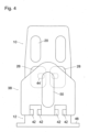
- Fig. 4 shows a side view of the housings 10, 12 in the locked state.
- the side walls of the housing 10, one of which is partially visible in this view, have two recesses 28, in each of which one of the projections 40 is guided.
- the projections 44 are located on a triangular extension that extends the corresponding leg of the release ring 38 upwards.
- two sets of release bevels 42 are formed, one set for each of the two locking tabs located on this side of the housing 10.
- a grip recess 50 is formed, which facilitates gripping and adjusting the release ring.
Landscapes
- Details Of Connecting Devices For Male And Female Coupling (AREA)
Description
- Die Erfindung betrifft eine Verriegelungseinrichtung für Leitungsverbinder, mit einem ersten Gehäuse und einem zweiten Gehäuse, die in einer Eingriffsrichtung gegeneinander ansetzbar sind, einem Satz von elastischen Verriegelungslaschen, die durch Befestigungsorgane an dem ersten Gehäuse gehalten und verrastend an Verriegelungsvorsprüngen des zweiten Gehäuses verriegelbar sind, und mit einem in der Eingriffsrichtung auf den Gehäusen verschiebbaren Entriegelungsring, der Entriegelungsschrägen zum Überführen der Verriegelungslaschen in eine entriegelte Stellung aufweist.
- Solche Verriegelungseinrichtungen dienen beispielsweise zur Verrieglung von zueinander komplementären Steckverbindern, beispielsweise elektrischen Steckverbindern, die jeweils in einem der beiden Gehäuse aufgenommen sind, so dass dadurch, dass die beiden Gehäuse aneinander verriegelt werden, auch die Steckverbinder in ihrer Eingriffsstellung gehalten werden.
- Insbesondere befasst sich die Erfindung mit Verriegelungseinrichtungen für Verbinder, die relativ große Abmessungen, beispielsweise in der Größenordnung von mehreren Zentimetern aufweisen, so dass auch die zur Aufnahme der Verbinder dienenden Gehäuse entsprechend große Abmessungen haben müssen und ein relativ hohes Gewicht aufweisen. Da bei der Handhabung dieser Verbinder und der zugehörigen Gehäuse relativ große Kräfte auftreten können, gelten für die Verriegelungseinrichtungen hohe Stabilitätsanforderungen.
- Aus
EP 1 729 377 A1 ist eine Verriegelungseinrichtung der eingangs genannten Art bekannt, bei der die Befestigungsorgane an die Wand des ersten Gehäuses angeformt sind und Einsteckschlitze definieren, in welche die Befestigungslaschen eingesteckt werden können. Entsprechend werden auch die Verriegelungsvorsprünge des zweiten Gehäuses durch Anformungen an der Gehäusewand gebildet . - Das Deutsche Patent- und Markenamt hat in der Prioritätsanmeldung zur vorliegenden Anmeldung den folgenden Stand der Technik recherchiert:
DE 36 24 678 A1 ,DE 20 2006 004 794 U1 ,DE 12 44 499 A ,US 6,030,244 A undEP 1 729 377 A1 . - Aufgabe der Erfindung ist es, eine Verriegelungseinrichtung zu schaffen, die sich rationell in einer Vielzahl von Varianten für Verbinder mit unterschiedlichen Abmessungen und unterschiedlichen Stabilitätsanforderungen herstellen lässt.
- Diese Aufgabe wird erfindungsgemäß dadurch gelöst, dass die Befestigungsorgane und die Verriegelungsvorsprünge als Zapfen ausgebildet sind, die in Umfangswände der beiden Gehäuse eingelassen sind.
- Bei dieser Verriegelungseinrichtung braucht somit keines der beiden Gehäuse besondere Anformungen für die Verriegelungslaschen aufzuweisen. Damit können die Werkzeugkosten für die Fertigung der Gehäuse beträchtlich reduziert werden. Für eine stabile Anbringung der Befestigungsorgane und der Verriegelungsvorsprünge genügt es, geeignete Bohrungen in den Gehäusewänden auszubilden, in denen dann die zapfenförmigen Befestigungsorgane und Verriegelungsvorsprünge verankert werden, beispielsweise mittels Gewinde- oder Nietverbindungen. Die Anzahlen und Positionen der Verriegelungslaschen lassen sich dann flexibel an die jeweilige Form und Größe der Gehäuse und die Stabilitätsanforderungen anpassen.
- Vorteilhafte Ausgestaltungen der Erfindung sind in den Unteransprüchen angegeben. In einer Ausführungsform werden die Befestigungsorgane und die Verriegelungsvorsprünge durch Nietzapfen gebildet. Die Verriegelungsvorsprünge können dann einfach durch Nietköpfe dieser Zapfen gebildet werden. Die Befestigungslaschen können beispielsweise durch Federbleche gebildet werden, die jeweils ein Loch für den zur Befestigung dienenden Nietzapfen aufweisen. In einer gegenüber dem Nietloch versetzten Position können diese Federbleche eine Auflaufschräge für den Verriegelungsvorsprung sowie ein weiteres Loch aufweisen, in das im verriegelten Zustand der Verriegelungsvorsprung eingreift. Wenn dann das erste Gehäuse an das zweite Gehäuse angesetzt wird, so laufen die Auflaufschrägen der Federbleche auf die Verriegelungsvorsprünge auf und werden dadurch elastisch aufgeweitet, bis die Verriegelungsvorsprünge in den Öffnungen der Federbleche einrasten. Auf diese Weise wird eine zugfeste Verbindung zwischen den beiden Gehäusen geschaffen, die sich nur dadurch wieder lösen lässt, dass die Federbleche mit Hilfe der Entriegelungsschrägen des Entriegelungsrings von den Wänden des zweiten Gehäuses weggebogen werden, so dass sie die als Verriegelungsvorsprünge dienenden Nietköpfe wieder frei geben. Die Auflaufschrägen der Federbleche können zugleich als Gegenflächen für die Entriegelungsschrägen dienen.
- Im folgenden wird ein Ausführungsbeispiel anhand der Zeichnung näher erläutert.
- Es zeigen:
- Fig. 1
- einen axialen Schnitt durch zwei miteinander verriegelte Gehäuse einer erfindungsgemäßen Verriegelungseinrichtung;
- Fig. 2
- die Verriegelungseinrichtung nach
Fig. 1 im entriegelten Zustand; - Fig. 3
- eine Frontansicht der beiden nach Entriegelung voneinander gelösten Gehäuse; und
- Fig. 4
- eine Seitenansicht der aneinander verriegelten Gehäuse.
- In
Fig. 1 sind in einem axialen Schnitt ein erstes Gehäuse 10 und ein zweites Gehäuse 12 gezeigt, die in einer Eingriffsrichtung A aneinander angesetzt und miteinander verriegelt sind. Jedes der beiden Gehäuse 10, 12 dient zur Aufnahme einer von zwei komplementären Komponenten eines nicht gezeigten Steckverbinders, beispielsweise eines elektrischen Steckverbinders. Im Inneren weisen beide Gehäuse 10, 12 Einbauten 14, 16 auf, die zum Positionieren und Fixieren der Komponenten des Steckverbinders dienen. Das erste Gehäuse 10 weist außerdem in der Wand, die inFig. 1 in der Innenansicht gezeigt ist, eine Durchführung 18 für ein elektrisches Anschlusskabel auf. - In den beiden im Schnitt dargestellten Wänden des ersten Gehäuses 10 sind Griffmulden 20 gebildet. Als Beispiel kann angenommen werden, dass das Gehäuse in der Breite so dimensioniert ist, dass es gerade noch mit dem Daumen und den Fingern einer Hand umspannt werden kann.
- Die beiden Gehäuse 10, 12 können aus Kunststoff oder auch aus Metall hergestellt sein.
- Das zweite Gehäuse 12 weist an seinem oberen Rand eine Dichtung 22 auf, auf die das erste Gehäuse 10 mit seinem unteren Rand aufgesetzt ist.
- In der Nähe seines unteren Randes weist das erste Gehäuse 10 in den beiden im Schnitt dargestellten Seitenwänden jeweils zwei Nietzapfen 24 auf, von denen jeweils nur einer sichtbar und im Schnitt dargestellt ist. Jeder Nietzapfen 24 durchgreift auf der Gehäuseaußenseite ein Nietloch einer Verriegelungslasche 26, die im gezeigten Beispiel durch einen Streifen aus Federstahlblech gebildet wird. Ein gekröpfter oberer Rand der Verriegelungslasche greift in eine flache Mulde 28 ein, die in der Außenwand des ersten Gehäuses 10 gebildet ist. Dadurch wird die Verriegelungslasche 26 so positioniert, dass sie sich von dem Nietzapfen 24 aus vertikal nach unten erstreckt. Durch den Kopf des Nietzapfens 24 wird die Verriegelungslasche in fester Anlage an der Außenwand des Gehäuses 10 gehalten. Ein unterhalb des Nietzapfens 24 liegender Teil der Verriegelungslasche ist von der Gehäusewand weg gebogen und läuft dann schräg nach unten auf die Außenfläche der Wand des zweiten Gehäuses 12 zu. In diesem schräg auf das zweite Gehäuse 12 zulaufenden Abschnitt hat die Verriegelungslasche ein Langloch 30, das von einem Verriegelungsvorsprung 32 des zweiten Gehäuses 12 durchgriffen wird. Bei diesem Verriegelungsvorsprung 32 handelt es sich um den Kopf eines weiteren Nietzapfens 34, der fest in die Umfangswand des zweiten Gehäuses 12 eingenietet ist. Unterhalb des Nietzapfens 34 bildet die Verriegelungslasche 26 eine von der Gehäusewand abgespreizte Auflaufschräge 36.
- Die beiden Gehäuse 10, 12 sind in Höhe der Dichtung 22 von einem Entriegelungsring 38 umgeben, der innenseitig für jede Verriegelungslasche eine Tasche 40 bildet, in der die Köpfe der Nietzapfen 24 und 34 sowie die Verriegelungslasche 26 aufgenommen sind. An seinem unteren Rand bildet der Entriegelungsring 38 eine Entriegelungsschräge 42, die sich in dem in
Fig. 1 gezeigten Zustand etwas unterhalb der Auflaufschräge 36 der Verriegelungslasche befindet. - Der Entriegelungsring 38 ist axial, also parallel zu der Eingriffsrichtung A verschiebbar am ersten Gehäuse 10 geführt. Der obere Rand der Tasche 40 bildet einen Anschlag für den Kopf des Nietzapfens 24, wodurch das Bewegungsspiel des Entriegelungsrings nach unten in
Fig. 1 begrenzt wird. Weiter oberhalb weist der Entriegelungsring zwei auf gleicher Höhe liegende Vorsprünge 44 auf, die jeweils in eine der Mulden 28 eingreifen und so das Bewegungsspiel des Verriegelungsrings nach oben begrenzen. - Das erste Gehäuse 10 kann auf die folgende Weise auf dem zweiten Gehäuse 12 montiert und an diesem verriegelt werden. Zunächst wird Entriegelungsring 38 in seine untere Endlage geschoben oder er fällt von selbst in die untere Endlage, wenn das erste Gehäuse 10 an seinem oberen Teil erfasst wird. Das Gehäuse 10 wird dann auf die Dichtung 22 aufgesetzt, wobei der Verriegelungsring 38 mit seinem unteren Teil über die Köpfe der Nietzapfen 34 hinweggeschoben wird. Die Verriegelungslaschen 26 laufen mit ihren Auflaufschrägen 36 auf die Köpfe dieser Nietzapfen 34 auf und werden dadurch vorübergehend elastisch nach außen gespreizt. Sobald die unteren Ränder der Langlöcher 30 die Nietköpfe passiert haben, federn die Verriegelungslaschen elastisch in die in
Fig. 1 gezeigte Stellung zurück, und die Verriegelung ist hergestellt. Die Teile des Entriegelungsrings 38, die den Boden der Taschen 40 bilden, verhindern, dass die Verriegelungslaschen 26 elastisch gespreizt werden und sich von den Verriegelungsvorsprüngen 32 lösen. - Wenn die Verriegelung gelöst werden soll, so wird der Entriegelungsring 38 nach oben in die in
Fig. 2 gezeigte Position gezogen. Dabei gleiten die Entriegelungsschrägen 42 auf die nach außen gebogenen unteren Enden der Verriegelungslaschen 26 auf und bewirken deren Spreizung. Da sich der Verriegelungsring 38 insgesamt nach oben bewegt hat, können die Verriegelungslaschen 26 so weit gespreizt werden, bis der Teil, der das Langloch 30 bildet, am Boden der Tasche 40 anliegt und der Verriegelungsvorsprung 32 aus dem Langloch ausgetreten ist. Der Verriegelungsring 38 erreicht dabei seine obere Endlage. Wenn er weiter nach oben gezogen wird, so wird folglich das erste Gehäuse 10 von dem zweiten Gehäuse 12 abgezogen. Im weiteren Verlauf dieser Abzugsbewegung bewegen sich die Teile des Entriegelungsrings, die die Entriegelungsschrägen 42 bilden, aufwärts an den Verriegelungsvorsprüngen 32 vorbei, bis schließlich auch der Verriegelungsring 38 vollständig von dem zweiten Gehäuse freigekommen ist. Sobald der Entriegelungsring losgelassen wird, sorgen die Schwerkraft und die Rückstellkräfte der Verriegelungslaschen 26 dafür, dass der Entriegelungsring relativ zum ersten Gehäuse 10 wieder in die Ausgangsstellung nachFig. 1 zurückkehrt. -
Fig. 3 zeigt eine Ansicht, in der die Gehäuse 10, 12 ganz voneinander gelöst sind, der Entriegelungsring 38 sich aber noch in seiner angehobenen Position relativ zum Gehäuse 10 befindet. In dieser Ansicht ist zu erkennen, dass der Entriegelungsring 38 längs einer Teilungsnaht 46 in zwei miteinander verrastete Halbschalen unterteilt ist. Das untere Gehäuse 12 hat an seinem unteren Rand auf der Vorderseite und auf der Rückseite einen Anschlussflansch 48, der den Anbau an ein nicht gezeigtes weiteres Bauteil ermöglicht. -
Fig. 4 zeigt eine Seitenansicht der Gehäuse 10, 12 im verriegelten Zustand. Die Seitenwände des Gehäuses 10, von denen eine in dieser Ansicht teilweise sichtbar ist, haben zwei Mulden 28, in denen jeweils einer der Vorsprünge 40 geführt ist. Die Vorsprünge 44 befinden sich an einem dreieckigen Fortsatz, der den betreffenden Schenkel des Entriegelungsrings 38 nach oben verlängert. Am unteren Rand dieses Schenkels sind zwei Sätze von Entriegelungsschrägen 42 gebildet, je ein Satz für jede der beiden Verriegelungslaschen, die sich auf dieser Seite des Gehäuses 10 befinden. In der Mitte dieses Schenkels des Entriegelungsrings ist eine Griffmulde 50 gebildet, die das Erfassen und Verstellen des Entriegelungsrings erleichtert.
Claims (10)
- Verriegelungseinrichtung für Leitungsverbinder, mit einem ersten Gehäuse (10) und einem zweiten Gehäuse (12), die in einer Eingriffsrichtung (A) gegeneinander ansetzbar sind, einem Satz von elastischen Verriegelungslaschen (26), die durch Befestigungsorgane an dem ersten Gehäuse (10) gehalten und verrastend an Verriegelungsvorsprüngen (32) des zweiten Gehäuses (12) verriegelbar sind, und mit einem in der Eingriffsrichtung (A) auf den Gehäusen (10, 12) verschiebbaren Entriegelungsring (38), der Entriegelungsschrägen (42) zum Überführen der Verriegelungslaschen (26) in eine entriegelte Stellung aufweist, dadurch gekennzeichnet, dass die Befestigungsorgane und die Verriegelungsvorsprünge (32) als Zapfen (24, 34) ausgebildet sind, die in Umfangswände der beiden Gehäuse (10, 12) eingelassen sind.
- Verriegelungseinrichtung nach Anspruch 1, bei der die Zapfen (24, 34) Nietzapfen sind.
- Verriegelungseinrichtung nach Anspruch 1 oder 2, bei der die Verriegelungslaschen (26) als Federbleche ausgebildet sind, die mittels der Nietzapfen (24) außenseitig an die Wände des ersten Gehäuses (10) angenietet sind.
- Verriegelungseinrichtung nach einem der vorstehenden Ansprüche, bei dem jede Verriegelungslasche (26) eine Öffnung (30) für den Eingriff des Verriegelungsvorsprungs (32) aufweist, der durch den Kopf eines der Nietzapfen (34) gebildet wird.
- Verriegelungseinrichtung nach einem der vorstehenden Ansprüche, bei dem jede Verriegelungslasche (26) an ihrem dem zweiten Gehäuse (10) zugewandten Ende einen nach außen gespreizten Abschnitt aufweist, der eine Auflaufschräge (36) für den Verriegelungsvorsprung (32) bildet.
- Verriegelungseinrichtung nach Anspruch 5, bei der die Entriegelungsschrägen (42) des Entriegelungsrings (38) so angeordnet sind, dass sie an den gespreizten, die Auflaufschrägen (36) bildenden Abschnitten der Verriegelungslaschen (26) angreifen.
- Verriegelungseinrichtung nach einem der vorstehenden Ansprüche, bei der der Entriegelungsring (38) für jede der Verriegelungslaschen (26) innenseitig eine Tasche (40) aufweist, die in der Verriegelungsstellung die Verriegelungslasche (26) sowie die zugehörigen Nietköpfe der Nietzapfen (24, 34) aufnimmt und die Auswärts-Schwenkbewegung der Verriegelungslasche begrenzt.
- Verriegelungseinrichtung nach einem der vorstehenden Ansprüche, bei der der Verschiebeweg des Entriegelungsrings (38) relativ zum ersten Gehäuse (10) in beiden Richtungen durch Anschläge begrenzt ist.
- Verriegelungseinrichtung nach den Ansprüchen 7 und 8, bei der einer der Anschläge durch ein Ende der Tasche (40) und durch den Nietkopf des Nietzapfens (24) gebildet wird, der das Befestigungsorgan für die Verriegelungslasche (26) bildet.
- Verriegelungseinrichtung nach Anspruch 8 oder 9, bei der einer der Anschläge durch einen Vorsprung (44) gebildet wird, der von dem Entriegelungsring (38) in Richtung auf die Umfangswand des ersten Gehäuses (10) vorspringt und in eine in dieser Umfangswand gebildete Mulde (28) eingreift.
Applications Claiming Priority (2)
| Application Number | Priority Date | Filing Date | Title |
|---|---|---|---|
| DE102021115005.1A DE102021115005B3 (de) | 2021-06-10 | 2021-06-10 | Verriegelungseinrichtung für Leitungsverbinder |
| PCT/DE2022/100417 WO2022258108A1 (de) | 2021-06-10 | 2022-06-03 | Verriegelungseinrichtung für leitungsverbinder |
Publications (2)
| Publication Number | Publication Date |
|---|---|
| EP4352832A1 EP4352832A1 (de) | 2024-04-17 |
| EP4352832B1 true EP4352832B1 (de) | 2025-04-30 |
Family
ID=82846585
Family Applications (1)
| Application Number | Title | Priority Date | Filing Date |
|---|---|---|---|
| EP22751640.8A Active EP4352832B1 (de) | 2021-06-10 | 2022-06-03 | Verriegelungseinrichtung für leitungsverbinder |
Country Status (6)
| Country | Link |
|---|---|
| US (1) | US20240250472A1 (de) |
| EP (1) | EP4352832B1 (de) |
| KR (1) | KR20240018600A (de) |
| CN (1) | CN117480691A (de) |
| DE (1) | DE102021115005B3 (de) |
| WO (1) | WO2022258108A1 (de) |
Family Cites Families (12)
| Publication number | Priority date | Publication date | Assignee | Title |
|---|---|---|---|---|
| BE621282A (de) | 1962-05-10 | |||
| DE3624678A1 (de) | 1986-07-22 | 1988-01-28 | Messerschmitt Boelkow Blohm | Verriegelbare mehrpolige steckverbindung in rechteckform |
| AU2079397A (en) | 1996-03-15 | 1997-10-01 | Biw Connector Systems, Inc. | Improved connectors and methods |
| FR2764127B1 (fr) * | 1997-05-29 | 1999-09-03 | Air Lb Gmbh | Connecteur electrique a verrouillage |
| DE102005025769B3 (de) * | 2005-06-04 | 2006-09-21 | Harting Electric Gmbh & Co. Kg | Verriegelungseinrichtung für Steckverbinder |
| DE202006004794U1 (de) | 2006-03-23 | 2007-07-26 | Weidmüller Interface GmbH & Co. KG | Gehäuse |
| DE102009041371A1 (de) * | 2009-09-11 | 2011-03-24 | Harting Electric Gmbh & Co. Kg | Verriegelungssystem für mehrteilige Gehäuse |
| DE102010038266B4 (de) * | 2010-10-19 | 2013-05-23 | Harting Electric Gmbh & Co. Kg | Mehrteiliges Steckverbindergehäuse |
| DE102012104857B4 (de) * | 2012-06-05 | 2016-03-24 | Wago Verwaltungsgesellschaft Mbh | Elektrische Steckverbindung |
| DE202015008407U1 (de) * | 2015-07-29 | 2015-12-21 | Industria Lombarda Materiale Elettrico I.L.M.E. S.P.A. | Korrosions- und erosionsgeschütztes Steckverbindergehäuse |
| LU93269B1 (de) * | 2016-10-20 | 2018-05-30 | Phoenix Contact Gmbh & Co Kg Intellectual Property Licenses & Standards | Push-Pull-Steckverbinderteil mit einem Rastblech |
| JP6451729B2 (ja) * | 2016-12-28 | 2019-01-16 | 第一精工株式会社 | 電気コネクタ及び電気コネクタ対 |
-
2021
- 2021-06-10 DE DE102021115005.1A patent/DE102021115005B3/de active Active
-
2022
- 2022-06-03 CN CN202280041635.9A patent/CN117480691A/zh active Pending
- 2022-06-03 WO PCT/DE2022/100417 patent/WO2022258108A1/de not_active Ceased
- 2022-06-03 EP EP22751640.8A patent/EP4352832B1/de active Active
- 2022-06-03 US US18/560,418 patent/US20240250472A1/en active Pending
- 2022-06-03 KR KR1020247000475A patent/KR20240018600A/ko not_active Ceased
Also Published As
| Publication number | Publication date |
|---|---|
| KR20240018600A (ko) | 2024-02-13 |
| US20240250472A1 (en) | 2024-07-25 |
| DE102021115005B3 (de) | 2022-10-06 |
| WO2022258108A1 (de) | 2022-12-15 |
| EP4352832A1 (de) | 2024-04-17 |
| CN117480691A (zh) | 2024-01-30 |
Similar Documents
| Publication | Publication Date | Title |
|---|---|---|
| EP3286806B1 (de) | Halterahmen zur halterung von steckverbindermodulen | |
| DE2054201C3 (de) | Zur Verwendung in einem elektrischen Steckverbinder bestimmtes elektrisches Kontaktelement | |
| EP2339701B1 (de) | Leiterplattensteckverbinder mit Verriegelungsvorrichtung | |
| DE2534472C2 (de) | ||
| DE102017208784B4 (de) | Steckverbinder | |
| EP3843221B1 (de) | Halterahmen für einen steckverbinder | |
| DE102018128042A1 (de) | Set aus Steckverbinder und Haltelement sowie Steckverbinder und Haltelement hierzu | |
| DE102018213924A1 (de) | Gehäuse für elektrischen Anschluss mit freigebbaren Anschlussverriegelungen | |
| DE602005000836T2 (de) | Elektrischer Steckverbinder | |
| EP3861600A1 (de) | Kontaktträger mit stabiler rastvorrichtung | |
| DE102023105747A1 (de) | Steckverbinder, Halteelement sowie Set aus einem Steckverbinder und einem Halteelement | |
| CH653175A5 (de) | Leiterplattenhalter fuer einen schmelzeinsatz einer elektrischen sicherung. | |
| EP4352832B1 (de) | Verriegelungseinrichtung für leitungsverbinder | |
| WO2002027373A9 (de) | Kupplungseinrichtung für glasfaserverbinder | |
| DE202010004995U1 (de) | Befestiger zur Befestigung eines ersten Bauteils an einem zweiten Bauteil | |
| DE10035726A1 (de) | Kontaktträger | |
| DE102004002850B4 (de) | Elektrischer Steckverbinder | |
| DE202017101632U1 (de) | Steckeranordnung und Verriegelungseinrichtung zur Verriegelung eines Gegensteckverbinders an einem Steckverbinder | |
| BE1032383B1 (de) | Halterahmen für einen Steckverbinder | |
| DE10324581B3 (de) | Spreizniet | |
| DE102019106093B4 (de) | Halterahmen sowie Steckverbinder mit einem derartigen Halterahmen | |
| DE102008007135A1 (de) | Befestigungselement | |
| EP4292171A1 (de) | Elektrischer steckverbinder | |
| EP3142519A1 (de) | Werkzeughalterbasiseinsatz, werkzeughalteranordnung und verfahren zum montieren des mindestens einen werkzeughalterbasiseinsatzes in der werkzeughalteranordnung | |
| DE102006020225B4 (de) | Reihenklemme mit einem Isoliergehäuse |
Legal Events
| Date | Code | Title | Description |
|---|---|---|---|
| STAA | Information on the status of an ep patent application or granted ep patent |
Free format text: STATUS: UNKNOWN |
|
| STAA | Information on the status of an ep patent application or granted ep patent |
Free format text: STATUS: THE INTERNATIONAL PUBLICATION HAS BEEN MADE |
|
| PUAI | Public reference made under article 153(3) epc to a published international application that has entered the european phase |
Free format text: ORIGINAL CODE: 0009012 |
|
| STAA | Information on the status of an ep patent application or granted ep patent |
Free format text: STATUS: REQUEST FOR EXAMINATION WAS MADE |
|
| 17P | Request for examination filed |
Effective date: 20230123 |
|
| AK | Designated contracting states |
Kind code of ref document: A1 Designated state(s): AL AT BE BG CH CY CZ DE DK EE ES FI FR GB GR HR HU IE IS IT LI LT LU LV MC MK MT NL NO PL PT RO RS SE SI SK SM TR |
|
| DAV | Request for validation of the european patent (deleted) | ||
| DAX | Request for extension of the european patent (deleted) | ||
| GRAP | Despatch of communication of intention to grant a patent |
Free format text: ORIGINAL CODE: EPIDOSNIGR1 |
|
| STAA | Information on the status of an ep patent application or granted ep patent |
Free format text: STATUS: GRANT OF PATENT IS INTENDED |
|
| INTG | Intention to grant announced |
Effective date: 20241218 |
|
| GRAS | Grant fee paid |
Free format text: ORIGINAL CODE: EPIDOSNIGR3 |
|
| GRAA | (expected) grant |
Free format text: ORIGINAL CODE: 0009210 |
|
| STAA | Information on the status of an ep patent application or granted ep patent |
Free format text: STATUS: THE PATENT HAS BEEN GRANTED |
|
| AK | Designated contracting states |
Kind code of ref document: B1 Designated state(s): AL AT BE BG CH CY CZ DE DK EE ES FI FR GB GR HR HU IE IS IT LI LT LU LV MC MK MT NL NO PL PT RO RS SE SI SK SM TR |
|
| REG | Reference to a national code |
Ref country code: CH Ref legal event code: EP Ref country code: GB Ref legal event code: FG4D Free format text: NOT ENGLISH |
|
| REG | Reference to a national code |
Ref country code: IE Ref legal event code: FG4D Free format text: LANGUAGE OF EP DOCUMENT: GERMAN |
|
| REG | Reference to a national code |
Ref country code: DE Ref legal event code: R096 Ref document number: 502022003802 Country of ref document: DE |
|
| PGFP | Annual fee paid to national office [announced via postgrant information from national office to epo] |
Ref country code: DE Payment date: 20250626 Year of fee payment: 4 |
|
| PGFP | Annual fee paid to national office [announced via postgrant information from national office to epo] |
Ref country code: FR Payment date: 20250624 Year of fee payment: 4 |
|
| PGFP | Annual fee paid to national office [announced via postgrant information from national office to epo] |
Ref country code: AT Payment date: 20250721 Year of fee payment: 4 |
|
| REG | Reference to a national code |
Ref country code: NL Ref legal event code: MP Effective date: 20250430 |
|
| PG25 | Lapsed in a contracting state [announced via postgrant information from national office to epo] |
Ref country code: PT Free format text: LAPSE BECAUSE OF FAILURE TO SUBMIT A TRANSLATION OF THE DESCRIPTION OR TO PAY THE FEE WITHIN THE PRESCRIBED TIME-LIMIT Effective date: 20250901 Ref country code: FI Free format text: LAPSE BECAUSE OF FAILURE TO SUBMIT A TRANSLATION OF THE DESCRIPTION OR TO PAY THE FEE WITHIN THE PRESCRIBED TIME-LIMIT Effective date: 20250430 Ref country code: ES Free format text: LAPSE BECAUSE OF FAILURE TO SUBMIT A TRANSLATION OF THE DESCRIPTION OR TO PAY THE FEE WITHIN THE PRESCRIBED TIME-LIMIT Effective date: 20250430 |
|
| REG | Reference to a national code |
Ref country code: LT Ref legal event code: MG9D |
|
| PG25 | Lapsed in a contracting state [announced via postgrant information from national office to epo] |
Ref country code: GR Free format text: LAPSE BECAUSE OF FAILURE TO SUBMIT A TRANSLATION OF THE DESCRIPTION OR TO PAY THE FEE WITHIN THE PRESCRIBED TIME-LIMIT Effective date: 20250731 Ref country code: NO Free format text: LAPSE BECAUSE OF FAILURE TO SUBMIT A TRANSLATION OF THE DESCRIPTION OR TO PAY THE FEE WITHIN THE PRESCRIBED TIME-LIMIT Effective date: 20250730 |
|
| PG25 | Lapsed in a contracting state [announced via postgrant information from national office to epo] |
Ref country code: NL Free format text: LAPSE BECAUSE OF FAILURE TO SUBMIT A TRANSLATION OF THE DESCRIPTION OR TO PAY THE FEE WITHIN THE PRESCRIBED TIME-LIMIT Effective date: 20250430 Ref country code: PL Free format text: LAPSE BECAUSE OF FAILURE TO SUBMIT A TRANSLATION OF THE DESCRIPTION OR TO PAY THE FEE WITHIN THE PRESCRIBED TIME-LIMIT Effective date: 20250430 |
|
| PG25 | Lapsed in a contracting state [announced via postgrant information from national office to epo] |
Ref country code: BG Free format text: LAPSE BECAUSE OF FAILURE TO SUBMIT A TRANSLATION OF THE DESCRIPTION OR TO PAY THE FEE WITHIN THE PRESCRIBED TIME-LIMIT Effective date: 20250430 |
|
| PG25 | Lapsed in a contracting state [announced via postgrant information from national office to epo] |
Ref country code: HR Free format text: LAPSE BECAUSE OF FAILURE TO SUBMIT A TRANSLATION OF THE DESCRIPTION OR TO PAY THE FEE WITHIN THE PRESCRIBED TIME-LIMIT Effective date: 20250430 |
|
| PG25 | Lapsed in a contracting state [announced via postgrant information from national office to epo] |
Ref country code: RS Free format text: LAPSE BECAUSE OF FAILURE TO SUBMIT A TRANSLATION OF THE DESCRIPTION OR TO PAY THE FEE WITHIN THE PRESCRIBED TIME-LIMIT Effective date: 20250731 |
|
| PG25 | Lapsed in a contracting state [announced via postgrant information from national office to epo] |
Ref country code: IS Free format text: LAPSE BECAUSE OF FAILURE TO SUBMIT A TRANSLATION OF THE DESCRIPTION OR TO PAY THE FEE WITHIN THE PRESCRIBED TIME-LIMIT Effective date: 20250830 |
|
| PG25 | Lapsed in a contracting state [announced via postgrant information from national office to epo] |
Ref country code: LV Free format text: LAPSE BECAUSE OF FAILURE TO SUBMIT A TRANSLATION OF THE DESCRIPTION OR TO PAY THE FEE WITHIN THE PRESCRIBED TIME-LIMIT Effective date: 20250430 |
|
| P01 | Opt-out of the competence of the unified patent court (upc) registered |
Free format text: CASE NUMBER: UPC_APP_9188_4352832/2025 Effective date: 20251007 |
|
| PG25 | Lapsed in a contracting state [announced via postgrant information from national office to epo] |
Ref country code: DK Free format text: LAPSE BECAUSE OF FAILURE TO SUBMIT A TRANSLATION OF THE DESCRIPTION OR TO PAY THE FEE WITHIN THE PRESCRIBED TIME-LIMIT Effective date: 20250430 Ref country code: SM Free format text: LAPSE BECAUSE OF FAILURE TO SUBMIT A TRANSLATION OF THE DESCRIPTION OR TO PAY THE FEE WITHIN THE PRESCRIBED TIME-LIMIT Effective date: 20250430 |
|
| PG25 | Lapsed in a contracting state [announced via postgrant information from national office to epo] |
Ref country code: CZ Free format text: LAPSE BECAUSE OF FAILURE TO SUBMIT A TRANSLATION OF THE DESCRIPTION OR TO PAY THE FEE WITHIN THE PRESCRIBED TIME-LIMIT Effective date: 20250430 |
|
| PG25 | Lapsed in a contracting state [announced via postgrant information from national office to epo] |
Ref country code: EE Free format text: LAPSE BECAUSE OF FAILURE TO SUBMIT A TRANSLATION OF THE DESCRIPTION OR TO PAY THE FEE WITHIN THE PRESCRIBED TIME-LIMIT Effective date: 20250430 |
|
| PG25 | Lapsed in a contracting state [announced via postgrant information from national office to epo] |
Ref country code: SK Free format text: LAPSE BECAUSE OF FAILURE TO SUBMIT A TRANSLATION OF THE DESCRIPTION OR TO PAY THE FEE WITHIN THE PRESCRIBED TIME-LIMIT Effective date: 20250430 |
|
| REG | Reference to a national code |
Ref country code: CH Ref legal event code: H13 Free format text: ST27 STATUS EVENT CODE: U-0-0-H10-H13 (AS PROVIDED BY THE NATIONAL OFFICE) Effective date: 20260127 |
|
| PG25 | Lapsed in a contracting state [announced via postgrant information from national office to epo] |
Ref country code: IT Free format text: LAPSE BECAUSE OF FAILURE TO SUBMIT A TRANSLATION OF THE DESCRIPTION OR TO PAY THE FEE WITHIN THE PRESCRIBED TIME-LIMIT Effective date: 20250430 |
|
| PG25 | Lapsed in a contracting state [announced via postgrant information from national office to epo] |
Ref country code: MC Free format text: LAPSE BECAUSE OF FAILURE TO SUBMIT A TRANSLATION OF THE DESCRIPTION OR TO PAY THE FEE WITHIN THE PRESCRIBED TIME-LIMIT Effective date: 20250430 |
|
| REG | Reference to a national code |
Ref country code: DE Ref legal event code: R097 Ref document number: 502022003802 Country of ref document: DE |
|
| PG25 | Lapsed in a contracting state [announced via postgrant information from national office to epo] |
Ref country code: LU Free format text: LAPSE BECAUSE OF NON-PAYMENT OF DUE FEES Effective date: 20250603 |
|
| REG | Reference to a national code |
Ref country code: BE Ref legal event code: MM Effective date: 20250630 |
|
| PG25 | Lapsed in a contracting state [announced via postgrant information from national office to epo] |
Ref country code: RO Free format text: LAPSE BECAUSE OF FAILURE TO SUBMIT A TRANSLATION OF THE DESCRIPTION OR TO PAY THE FEE WITHIN THE PRESCRIBED TIME-LIMIT Effective date: 20250430 |
|
| PLBE | No opposition filed within time limit |
Free format text: ORIGINAL CODE: 0009261 |
|
| STAA | Information on the status of an ep patent application or granted ep patent |
Free format text: STATUS: NO OPPOSITION FILED WITHIN TIME LIMIT |
|
| REG | Reference to a national code |
Ref country code: CH Ref legal event code: L10 Free format text: ST27 STATUS EVENT CODE: U-0-0-L10-L00 (AS PROVIDED BY THE NATIONAL OFFICE) Effective date: 20260311 |
|
| 26N | No opposition filed |
Effective date: 20260202 |
|
| PG25 | Lapsed in a contracting state [announced via postgrant information from national office to epo] |
Ref country code: IE Free format text: LAPSE BECAUSE OF NON-PAYMENT OF DUE FEES Effective date: 20250603 |
|
| PG25 | Lapsed in a contracting state [announced via postgrant information from national office to epo] |
Ref country code: BE Free format text: LAPSE BECAUSE OF NON-PAYMENT OF DUE FEES Effective date: 20250630 |