EP4353345A1 - Séparateur air-eau pour échangeur de chaleur à condensation - Google Patents
Séparateur air-eau pour échangeur de chaleur à condensation Download PDFInfo
- Publication number
- EP4353345A1 EP4353345A1 EP23202524.7A EP23202524A EP4353345A1 EP 4353345 A1 EP4353345 A1 EP 4353345A1 EP 23202524 A EP23202524 A EP 23202524A EP 4353345 A1 EP4353345 A1 EP 4353345A1
- Authority
- EP
- European Patent Office
- Prior art keywords
- planar body
- flow
- liquid
- ramps
- apertures
- Prior art date
- Legal status (The legal status is an assumption and is not a legal conclusion. Google has not performed a legal analysis and makes no representation as to the accuracy of the status listed.)
- Granted
Links
Images



Classifications
-
- F—MECHANICAL ENGINEERING; LIGHTING; HEATING; WEAPONS; BLASTING
- F28—HEAT EXCHANGE IN GENERAL
- F28F—DETAILS OF HEAT-EXCHANGE AND HEAT-TRANSFER APPARATUS, OF GENERAL APPLICATION
- F28F25/00—Component parts of trickle coolers
- F28F25/02—Component parts of trickle coolers for distributing, circulating, and accumulating liquid
-
- B—PERFORMING OPERATIONS; TRANSPORTING
- B01—PHYSICAL OR CHEMICAL PROCESSES OR APPARATUS IN GENERAL
- B01D—SEPARATION
- B01D45/00—Separating dispersed particles from gases or vapours by gravity, inertia, or centrifugal forces
- B01D45/04—Separating dispersed particles from gases or vapours by gravity, inertia, or centrifugal forces by utilising inertia
- B01D45/08—Separating dispersed particles from gases or vapours by gravity, inertia, or centrifugal forces by utilising inertia by impingement against baffle separators
-
- F—MECHANICAL ENGINEERING; LIGHTING; HEATING; WEAPONS; BLASTING
- F28—HEAT EXCHANGE IN GENERAL
- F28F—DETAILS OF HEAT-EXCHANGE AND HEAT-TRANSFER APPARATUS, OF GENERAL APPLICATION
- F28F9/00—Casings; Header boxes; Auxiliary supports for elements; Auxiliary members within casings
- F28F9/005—Other auxiliary members within casings, e.g. internal filling means or sealing means
-
- B—PERFORMING OPERATIONS; TRANSPORTING
- B33—ADDITIVE MANUFACTURING TECHNOLOGY
- B33Y—ADDITIVE MANUFACTURING, i.e. MANUFACTURING OF THREE-DIMENSIONAL [3D] OBJECTS BY ADDITIVE DEPOSITION, ADDITIVE AGGLOMERATION OR ADDITIVE LAYERING, e.g. BY 3D PRINTING, STEREOLITHOGRAPHY OR SELECTIVE LASER SINTERING
- B33Y80/00—Products made by additive manufacturing
Definitions
- the present disclosure relates to heat exchangers, and more particularly to water separators for condensing heat exchangers.
- Closed-loop environmental systems such as the certain aircraft or spacecraft (e.g., the International Space Station), require water to be recycled and reused. This includes any water vapor that has been evaporated or exhaled inside of the system.
- a condensing heat exchanger has been used on spacecraft to control air temperature and humidity, and to extract excess water vapor from the air. The vapor condenses on the heat exchanger, adheres to its hydrophilic surface, and then is collected by a slurper. Typical slurpers, which separate and collect the water without diverting the air, may not operate with high efficiency due to material and design limitations.
- a system includes a liquid-gas separator.
- the liquid-gas separator comprises, a substantially planar body configured to be seated in a fluid flow to separate a flow of liquid from the fluid flow, one or more apertures disposed in the body configured collect the flow of liquid, and one or more diverters integrally formed on or in the body configured divert the flow of liquid towards the one or more apertures.
- the planar body can be additively manufactured.
- the one or more diverters can include a pair of ramps angled oblique to a longitudinal axis of the planar body and diverging away from the planar body configured to direct the fluid flow over the pair of ramps and to separate the flow of liquid from the fluid flow and divert the flow of liquid between the pair of ramps.
- the pair of ramps can be arranged to form a chevron pattern, and a respective aperture of the one or more apertures is disposed at a converging point of the chevron pattern.
- the pair of ramps can be a first pair of ramps in a plurality of pairs of ramps, and the plurality of pairs of ramps can be disposed along an axial length of the planar body, forming a plurality of chevrons.
- the planar body can be a first planar body, and the system can include a second substantially planar body configured to be seated in the fluid flow opposite the first planar body forming a flow channel therebetween.
- the second planar body can include one or more apertures disposed in the second planar body configured collect a flow of liquid, and one or more diverters integrally formed on or in the second planar body configured to separate the flow of liquid from the fluid flow and divert the flow of liquid from towards the one or more apertures.
- the one or more diverters of the second planar body can include a plurality of pairs of ramps angled oblique to a longitudinal axis of the planar body and diverging away from the second planar body configured to direct the fluid flow over each ramp of the plurality of pairs of ramps and to separate the flow of liquid from the fluid flow and divert the flow of liquid between each the pair of ramps.
- Each pair of ramps of the second planar body can be arranged to form a chevron pattern, and a respective aperture of the one or more apertures of the second planar body can be disposed at a converging point of the chevron pattern.
- the plurality of pairs of ramps of the second planar body can be disposed along an axial length of the second planar body, and in certain embodiments, the plurality of pairs of ramps and plurality of apertures of the second planar body can be axially offset from the plurality of pairs of ramps and the plurality of apertures of the first planar body.
- the one or more diverters can include a plurality of ramps arranged parallel to one another along an axial length of the planar body and diverging away from the planar body, the plurality of ramps configured to direct the fluid flow over each ramp of the plurality of ramps and to separate the flow of liquid from the fluid flow and divert the flow of liquid between each ramp of the plurality of ramps.
- the one or more apertures can be disposed in an alternating pattern with the plurality of ramps.
- the first planar body is a first planar body
- the system can also include a second substantially planar body configured to be seated in the fluid flow opposite the first planar body forming a flow channel therebetween.
- the second planar body can include one or more apertures disposed in the second planar body configured collect a flow of liquid, and one or more diverters integrally formed on or in the second planar body configured divert the flow of liquid from towards the one or more apertures.
- the one or more diverters of the second planar body can include a plurality of ramps arranged parallel to one another along an axial length of the second planar body and diverging away from the planar body, the plurality of ramps of the second planar body configured to direct the fluid flow over each ramp of the plurality of ramps and to separate the flow of liquid from the fluid flow and divert the flow of liquid between each ramp of the plurality of ramps.
- the plurality ramps and plurality of apertures of the second planar body can be axially offset from the plurality of ramps and the plurality of apertures of the first planar body.
- the one or more diverters can include a pair of ramps diverging away from the planar body and arranged such that an apex of each ramp in the pair of ramps are adjacent to one another and defining a trench therebetween.
- the one or more diverters can be configured to direct the fluid flow over each apex of the pair of ramps and over the trench and to separate the flow of liquid from the fluid flow and divert the flow of liquid into the trench.
- the one or more apertures can be disposed at a bottom of the trench.
- a drop off angle between the apex of each ramp and a side wall of the trench can be about 90 degrees.
- the planar body includes a plurality of diverters disposed along an axial length of the planar body.
- the planar body can be a first planar body
- the system can include a second substantially planar body configured to be seated in the fluid flow opposite the first planar body forming a flow channel therebetween.
- the second planar body can include one or more apertures disposed in the second planar body configured collect a flow of liquid and one or more diverters integrally formed on or in the second planar body configured divert the flow of liquid from towards the one or more apertures.
- the one or more diverters of the second planar body can include a pair of ramps diverging away from the second planar body and arranged such that an apex of each ramp in the pair of ramps are adjacent to one another and defining a trench therebetween, the one or more diverters of the second planar body configured to direct the fluid flow over each apex of the pair of ramps and over the trench and to separate the flow of liquid from the fluid flow and divert the flow of liquid into the trench.
- the second planar body can include a plurality of diverters disposed along an axial length of the second planar body, and in certain embodiments, the plurality of diverters of the second planar body can be axially offset from the diverters of the first planar body.
- the one or more diverters can include a hydrophilic coating disposed on one or more portions of the planar body configured to separate the flow of liquid from the fluid flow and divert the flow of liquid towards the one or more apertures. In certain embodiments, the one or more diverters can include a hydrophobic coating disposed on one or more portions of the planar body configured to separate the flow of liquid from the fluid flow and divert the flow of liquid towards the one or more apertures.
- the one or more diverters can include a divot defined in the planar body and converging into the planar body.
- the one or more apertures can be disposed at a bottom of the divot, the trench configured to direct the fluid flow over the divot and to separate the flow of liquid from the fluid flow and divert the flow of liquid into the divot.
- the planar body can include a hollow bar, and the one or more diverters can include a rounded edge of the hollow bar.
- the one or more apertures can include a plurality of apertures disposed along an axial length of the bar, and in certain embodiments, the plurality of apertures can be disposed in a face of the hollow bar parallel to the fluid flow.
- the one or more apertures can include a plurality of apertures disposed in a downstream edge of the hollow bar relative to the fluid flow to direct the fluid flow over the face of the planar body and configured to separate the flow of liquid from the fluid flow and divert the flow of liquid along the downstream edge of the hollow bar and into the plurality of apertures.
- the system can include a heat exchanger body having a heat exchanger core.
- the heat exchanger core can include airflow gas flow path defined between a gas inlet and a gas outlet and a condensate flow path defined between the one or more apertures of the liquid-gas separator and a condensate outlet.
- the liquid-gas separator can be disposed in the heat exchanger core in the gas flow path, and in certain embodiments the liquid-gas separator can be formed integrally with or by the heat exchanger core.
- the liquid-gas separator can be configured to separate the flow of liquid from a flow of gas, direct the flow of gas to the gas outlet and divert the flow of liquid to through the apertures and to the condensate outlet.
- the heat exchanger body can include a cross flow heat exchanger body, and can further include a liquid flow path defined between a liquid inlet and a liquid outlet, wherein the liquid flow path is fluidly isolated from the gas flow path and the condensate flow path.
- the liquid-gas separator can be configured separate the flow of liquid from a flow of gas, direct the flow of gas to the gas outlet and divert the flow of liquid through the apertures and to the condensate outlet in a weightless environment.
- the weightless environment can include a spacecraft in outer space.
- FIG. 1 an illustrative view of an embodiment of a system in accordance with the disclosure is shown in Fig. 1 and is designated generally by reference character 100.
- FIG. 2-14 Other embodiments and/or aspects of this disclosure are shown in Figs. 2-14 .
- a system 100 includes a heat exchanger body 102 having a heat exchanger core 103.
- the heat exchanger body 102 and core 103 can define, a gas flow path 104 defined between a gas inlet 106 and a gas outlet 108.
- a condensate flow path 110 can be defined between one or more apertures 212 of a liquid-gas separator 200 and a condensate outlet 114.
- the liquid-gas separator 200 can be disposed in the heat exchanger body 102 in a fluid flow path 105 (e.g., the gas flow path 104 having a mixture of liquid and gas therein).
- the liquid-gas separator 200 can be configured to separate the fluid flow 105 into the flow of gas 104 and a flow of liquid 110.
- the liquid-gas separator 200 can also be configured to direct the flow of gas 104 to the gas outlet 106 and divert the flow of liquid 110 from the fluid flow 105 to and through the apertures 212 and to the condensate outlet 114.
- the heat exchanger body 102 can include a cross flow heat exchanger body, and can further include a liquid flow path 116 defined between a liquid inlet 118 and a liquid outlet 120, wherein the liquid flow path 116 is fluidly isolated from gas flow path 104 and the condensate flow path 110.
- the separator 200 can be configured to direct the flow of gas 104 to the gas outlet 106 and divert the flow of liquid 110 to and through the apertures 212 and to the condensate outlet 114 in a weightless environment, for example if the system 100 is included in a spacecraft 122 travelling to, from or within outer space at a constant velocity.
- the liquid-gas separator 200 can be or include an air-water separator configured to separate a flow of air (e.g., gas flow 104) and a flow of water (e.g., liquid flow 110) from the fluid flow 105.
- air-water separator 200 the liquid-gas separator 200 is hereinafter referred to as air-water separator 200, and the respective flows therein are referred to as flow of air 104 and flow of water 110.
- the separator 200 can be used for separating liquids and gases other than water and air as dictated by the particular heat exchanger or system with which it is used.
- the air-water separator 200 can include a substantially planar body 224 configured to be seated in the fluid flow 105 to separate the flow of water 110 from the flow of air 104 in the fluid flow 105.
- the one or more apertures 212 can be disposed in the body 224 configured collect the flow of water 110, and one or more diverters 226 can be integrally formed on or in the body 224 configured divert the flow of water 110 towards the one or more apertures 212.
- the planar body 224 can be additively manufactured.
- the one or more diverters 226 can include a pair of ramps 228 angled oblique to a longitudinal axis A of the planar body 224 and diverging away from the planar body 224 configured to direct the flow of air 104 over the pair of ramps 228 and to divert the flow of water 110 between the pair of ramps 228.
- the pair of ramps 228 can be arranged to form a chevron pattern, and a respective aperture of the one or more apertures 212 can be disposed at a converging point 230 of the chevron pattern.
- the apertures 212 can be included in any suitable location along the axial length of the body 224 and in any suitable pattern with respect to the ramps 228.
- the pair of ramps 228 can be a first pair of ramps 228a in a plurality of pairs of ramps, and the plurality of pairs of ramps can be disposed along an axial length of the planar body 224, forming a plurality of chevrons.
- the planar body 224 can be a first planar body 224a, and the system can include a second substantially planar body 224b configured to be seated in the fluid flow 105 opposite the first planar body 224a forming a flow channel 232 therebetween.
- the second planar body 224b can be substantially similar to the first planar body 224a.
- the plurality of pairs of ramps 228b and apertures 212b of the second planar body 224b can be disposed along an axial length of the second planar body 224b but can be axially offset from the plurality of pairs of ramps 228a and the plurality of apertures 212a of the first planar body 224a.
- the first and second planar bodies 224a, 224b can also be offset from each other in a direction perpendicular to the longitudinal axis A1, A2 of the first and second planar bodies 224a, 224b.
- the blockage in the fluid flow 105 created by the chevrons 228 will create a recirculation region for the airflow 104, causing the bulk blow to travel up the ramps and impinge on the opposite wall.
- the air-water separator 300 can be similar to that of the air-water separator 200, for example air-water separator 300 can have similar components and features with respect to air-water separator 200.
- the one or more diverters 326 can include a plurality of ramps 328 arranged parallel to one another along the axial length of the planar body 324 to direct the flow of air 104 over each ramp 328 and to divert the flow of water 110 between each ramp 328.
- the one or more apertures 212 can be disposed in an alternating pattern with the plurality of ramps 328.
- the plurality of ramps 328b and plurality of apertures 312b of the second planar body 324b can be axially offset from the plurality of ramps 328a and the plurality of apertures 312a of the first planar body 324a and in a direction perpendicular to the longitudinal axis of the planar bodies 324a, 324b.
- Orienting the ramps 328 in the direction of the air flow 104 will reduce the pressure drop created by the obstruction.
- Axially offsetting the ramps on the top (e.g., 328b) and bottom (e.g., 328a) will impinge the air 104 onto the opposite surface and encourage the water 110 towards the holes 312.
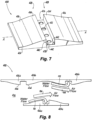
- FIG. 7 and 8 another embodiment of an air-water separator 400 is shown.
- the air-water separator 400 can be similar to that of the air-water separators 200, 300, for example air-water separator 400 can have similar components and features with respect to air-water separators 200, 300.
- the description of common elements that have been described above for air-water separators 200, 300 are not repeated with respect to air-water separator 400 as shown in Figs. 7-8 .
- the one or more diverters 426 can include a pair of ramps 428 diverging away from the planar body 424a and arranged such that an apex 434 of each ramp 426 are adjacent to one another and define a trench 436 therebetween.
- the one or more diverters 426 can be configured to direct the flow of air 104 over each apex 434 and over the trench 436 and to divert the flow of water 110 into the trench 434.
- the one or more apertures 414 can be disposed at a bottom 438 of the trench 436.
- a drop off angle 440 between the apex 434 of each ramp 428 and a side wall 442 of the trench 436 can be about 90 degrees.
- the air 104 will pass over the trench 436, because the Reynolds number of the air 104 will be too high to make the turn at the drop off angle 436 (e.g., in some case about 90 degrees).
- the water 110 will have a lower Reynolds number and will drop off into the trench 436, where it can drain into the apertures 412.
- a second planar body 424b (e.g., substantially similar to the first planar body 424a) can be included opposite the first planar body forming a flow channel 432 therebetween.
- the plurality of diverters 426b of the second planar body 424b can be axially offset from the diverters 426a of the first planar body 424a. Because of the axial offset, the channel 426 will have the same height along the entirety of the fluid flow path within the heat exchanger body.
- the one or more apertures can be included in any suitable pattern relative to the trench 436 and the ramps 428, for example, apertures 412 can additionally be included at the apex 434 of each ramp 428.
- One or more additional obstructions may be included along the length of the trench 436 to guide the water 110 toward the apertures 412.
- intermittent, discontinuous ⁇ speed bumps' may be included where the speed bumps on an upstream and downstream side of the planar body are different heights.
- the downstream speed bump would catch any water droplets that are still in the air stream and may have deflected off of the upstream speed bump, and direct the water to the respective aperture.
- the speed bump on the upstream side is taller than the downstream side, a stronger low-pressure region would be formed in the valley between the upstream and downstream speed bumps, while not obstructing any downstream flow.
- feature size/shape of the diverters on the planar body can be optimized based on one or more conditions, such as flow rate, water content, water adherence to a given surfaces, fluid type, and the like.
- the air-water separator 500 can be similar to that of the air-water separators 200, 300, 400, for example air-water separator 500 can have similar components and features with respect to air-water separators 200, 300, 400.
- the description of common elements that have been described above for air-water separators 200, 300, 400 are not repeated with respect to air-water separator 500 as shown in Figs. 9-11 .
- the one or more diverters 526 can include a divot 544 defined in the planar body 524 and converging into the planar body 524.
- the one or more apertures 512 can be disposed at a bottom (e.g., the lowest point) of the divot 544, the divot 544 configured to divert the flow of water 110 into the divot 544 and through the aperture 512 and to direct the flow of air 104 over the divot 544.
- the divot 544 can take any suitable shape, for example a flat rectangular recess as shown in Fig. 9 , a rectangular sloped recess converging into the planar body as shown in Fig. 10 , a trapezoidal sloped recess converging into the planar body as shown in Fig. 11 , or any suitable combination thereof.
- any one of air-water separators 500 as shown in Figs. 9-11 can include a second planar body positioned in the fluid flow opposite the first planar body to form a flow channel therebetween, the second planar body being offset from the first planar body in at least on direction (e.g., as described above with respect to air-water separators 200, 300, 400.
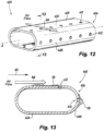
- FIG. 12 and 13 another embodiment of an air-water separator 600 is shown.
- the air-water separator 600 can be similar to that of the air-water separators 200, 300, 400, 500, for example air-water separator 600 can have similar components and features with respect to air-water separators 200, 300, 400, 500.
- the planar body 624 can include a hollow bar, and the one or more diverters 626 can include a rounded edge 648 of the hollow bar.
- the one or more apertures 612 can include a plurality of apertures 612 disposed along an axial length of the bar 624 in at least one of a face 650 or an edge 648 of the hollow bar 624.
- the plurality of apertures 612 can be disposed in a face 650 of the hollow bar 624 parallel to the fluid flow 105 and airflow 104.
- the one or more apertures 612 can additionally or alternatively include a plurality of apertures 612 disposed in a downstream edge (e.g., edge 648) of the hollow bar 624 relative to the fluid flow 105 to direct the flow of air 104 over the face 650 of the planar body 624 and configured to divert the flow of water 110 along the downstream edge 648 of the bar 624 and into the plurality of apertures 612.
- the planar body 624 can include a hydrophilic coating or a hydrophobic coating. If the surface tension force from the hydrophilic coating outweighs the viscous force from the airflow 104, the water 110 will remain attached to the bar 624 and collect on the back surface (e.g., downstream edge 648) and enter apertures 612.
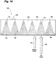
- FIG. 14 another embodiment of an air-water separator 700 is shown.
- the air-water separator 700 can be similar to that of the air-water separators 200, 300, 400, 500, 600, for example air-water separator 700 can have similar components and features with respect to air-water separators 200, 300, 400, 500, 600.
- the description of common elements that have been described above for air-water separators 200, 300, 400, 500, 600 are not repeated with respect to air-water separator 700 as shown in Fig. 14 .
- the one or more diverters 726 can include either or both of a hydrophilic 752 and/or a hydrophobic 754 coating disposed on one or more portions of the planar body 724 configured to divert the flow of water 110 towards the one or more apertures 712.
- a hydrophilic coating 752 can be disposed on the planar body 724 in a triangular pattern, where a point 754 of the triangle converges on a respective aperture 712. The remainder of the planar body 724 may be coated with the hydrophobic coating 754 to coax the water to the hydrophilic portions.
- the hydrophilic coating 752 can be selectively and strategically applied in a pattern that will help collect water 110 at the apertures 712. It is contemplated that the embodiment of the air-water separator 700 of Fig. 14 can be used in any suitable combination with any of the air-water separators described herein, e.g., any one or more of air-water separators 200, 300, 400, 500, 600.
- one or more portions, or an entirety of the air-water separator can be formed using additive manufacturing, which allows for more complicated designs than the castin condensing heat exchangers.
- the air-water separator can be formed using laser powder bed fusion, including titanium laser powder bed fusion.
- One such design includes chevrons added to the slurper bar (e.g., planar body 224, 324, 424, 524, 624, 724) to direct water droplets towards the collection holes, and shaped to create re-circulation zones for the air to reduce the amount of air leakage into the slurper.
- Another design can include trenches added along the length of the slurper to collect the water in a slot that the air will pass over. Holes are drilled at the bottom of the trench to drain the water into the slurper channel.
- Another design includes adding patterns in the hydrophilic coating and holes on the leeward edge of the slurper bar take advantage of the surface tension forces from the water.
- both the chevrons and trenches are designed to be offset on the top and bottom walls of the channel, to avoid a significant flow constriction.
- Embodiments as described herein can be additively manufactured, which simplifies manufacture and improves performance.
- Embodiments provide more effective and efficient isolation of water from the air more so more water can be collected with less air leakage. This improved effectiveness would require a lower pressure drop across the holes, which decreases the energy required to power the system.
- any numerical values disclosed herein can be exact values or can be values within a range. Further, any terms of approximation (e.g., “about”, “approximately”, “around”) used in this disclosure can mean the stated value within a range. For example, in certain embodiments, the range can be within (plus or minus) 20%, or within 10%, or within 5%, or within 2%, or within any other suitable percentage or number as appreciated by those having ordinary skill in the art (e.g., for known tolerance limits or error ranges).
- a reference to "A and/or B", when used in conjunction with open-ended language such as “comprising” can refer, in one embodiment, to A only (optionally including elements other than B); in another embodiment, to B only (optionally including elements other than A); in yet another embodiment, to both A and B (optionally including other elements); etc.
Landscapes
- Engineering & Computer Science (AREA)
- Physics & Mathematics (AREA)
- Thermal Sciences (AREA)
- Mechanical Engineering (AREA)
- General Engineering & Computer Science (AREA)
- Chemical & Material Sciences (AREA)
- Chemical Kinetics & Catalysis (AREA)
- Separating Particles In Gases By Inertia (AREA)
- Physical Or Chemical Processes And Apparatus (AREA)
Applications Claiming Priority (1)
| Application Number | Priority Date | Filing Date | Title |
|---|---|---|---|
| US17/963,120 US12487039B2 (en) | 2022-10-10 | 2022-10-10 | Air-water separator for condensing heat exchanger |
Publications (2)
| Publication Number | Publication Date |
|---|---|
| EP4353345A1 true EP4353345A1 (fr) | 2024-04-17 |
| EP4353345B1 EP4353345B1 (fr) | 2025-07-16 |
Family
ID=88373746
Family Applications (1)
| Application Number | Title | Priority Date | Filing Date |
|---|---|---|---|
| EP23202524.7A Active EP4353345B1 (fr) | 2022-10-10 | 2023-10-09 | Séparateur air-eau pour échangeur de chaleur à condensation |
Country Status (2)
| Country | Link |
|---|---|
| US (1) | US12487039B2 (fr) |
| EP (1) | EP4353345B1 (fr) |
Families Citing this family (2)
| Publication number | Priority date | Publication date | Assignee | Title |
|---|---|---|---|---|
| US12498184B2 (en) * | 2023-06-08 | 2025-12-16 | Raytheon Technologies Corporation | Uniform chemical milling |
| US20250230985A1 (en) * | 2024-01-12 | 2025-07-17 | Hamilton Sundstrand Space Systems International, Inc. | Integral additively manufactured fluid removal geometry |
Citations (4)
| Publication number | Priority date | Publication date | Assignee | Title |
|---|---|---|---|---|
| US3870494A (en) * | 1973-01-24 | 1975-03-11 | Dewitt H Doane | Grease filter for kitchen ventilators |
| US8470080B1 (en) * | 2012-02-22 | 2013-06-25 | Shale Oil And Gas Technologies Ltd | High pressure separator |
| US9643105B1 (en) * | 2016-12-01 | 2017-05-09 | Worthington Industries, Inc. | Inlet diverter |
| US20200149944A1 (en) * | 2018-11-10 | 2020-05-14 | Itron Global Sarl | Gas Meter Flow Straightener and Decontamination Device |
Family Cites Families (10)
| Publication number | Priority date | Publication date | Assignee | Title |
|---|---|---|---|---|
| US3570221A (en) * | 1969-02-20 | 1971-03-16 | Wilbert J Oliver | Two phase fluid-solid separator |
| US3868830A (en) | 1973-08-31 | 1975-03-04 | Nasa | Condensate removal device for heat exchanger |
| FR2570290B1 (fr) * | 1984-09-17 | 1987-01-09 | Framatome Sa | Dispositif de separation d'eau et de vapeur pour le sechage d'une vapeur humide |
| US5487849A (en) | 1993-12-03 | 1996-01-30 | Tower Tech, Inc. | Pultruded cooling tower construction |
| US5507858A (en) * | 1994-09-26 | 1996-04-16 | Ohio University | Liquid/gas separator and slug flow eliminator and process for use |
| US8124113B2 (en) | 2005-09-06 | 2012-02-28 | Hamilton Sundstrand Space Systems International, Inc. | Hydrophilic coating |
| MX337339B (es) * | 2010-09-30 | 2016-02-26 | Sulzer Chemtech Ag | Separador de gotas. |
| AU2016220515B2 (en) * | 2015-02-17 | 2019-02-28 | Exxonmobil Upstream Research Company | Inner surface features for co-current contactors |
| CN105737647B (zh) | 2016-03-22 | 2017-11-03 | 江苏远卓设备制造有限公司 | 一种用于汽水分离的板式换热器 |
| CN107091518A (zh) | 2017-04-13 | 2017-08-25 | 西安工程大学 | 一种人字型挡水板及其测定性能的方法 |
-
2022
- 2022-10-10 US US17/963,120 patent/US12487039B2/en active Active
-
2023
- 2023-10-09 EP EP23202524.7A patent/EP4353345B1/fr active Active
Patent Citations (4)
| Publication number | Priority date | Publication date | Assignee | Title |
|---|---|---|---|---|
| US3870494A (en) * | 1973-01-24 | 1975-03-11 | Dewitt H Doane | Grease filter for kitchen ventilators |
| US8470080B1 (en) * | 2012-02-22 | 2013-06-25 | Shale Oil And Gas Technologies Ltd | High pressure separator |
| US9643105B1 (en) * | 2016-12-01 | 2017-05-09 | Worthington Industries, Inc. | Inlet diverter |
| US20200149944A1 (en) * | 2018-11-10 | 2020-05-14 | Itron Global Sarl | Gas Meter Flow Straightener and Decontamination Device |
Also Published As
| Publication number | Publication date |
|---|---|
| EP4353345B1 (fr) | 2025-07-16 |
| US12487039B2 (en) | 2025-12-02 |
| US20240118047A1 (en) | 2024-04-11 |
Similar Documents
| Publication | Publication Date | Title |
|---|---|---|
| EP4353345B1 (fr) | Séparateur air-eau pour échangeur de chaleur à condensation | |
| US10222144B2 (en) | Methods and apparatus for a microtruss heat exchanger | |
| EP2697589B1 (fr) | Échangeur de chaleur | |
| EP3314189B1 (fr) | Échangeur de chaleur à microtube | |
| EP3467392B1 (fr) | Dispositif d'extraction d'eau amélioré à haute pression à bord raclé alimentant une chambre basse pression et élément hélicoïdal interne pour améliorer la collecte et le drainage de l'eau | |
| US11865556B2 (en) | Out-of-plane curved fluidic oscillator | |
| WO2018157663A1 (fr) | Dispositif de dépoussiérage et de désembuage par formation de brume froide | |
| US6260830B1 (en) | Film fill-pack for inducement of spiraling gas flow in heat and mass transfer contact apparatus with self-spacing fill-sheets | |
| US6315804B1 (en) | Drift eliminator | |
| GB2515463A (en) | A fuel cell system | |
| US20100095688A1 (en) | Refrigerant distribution improvement in parallell flow heat exchanger manifolds | |
| WO2005088220A1 (fr) | Paire de plaques a nervures croisees pour echangeur de chaleur | |
| CN118268056A (zh) | 一种冷凝液滴长距离高速自驱动运输的结构 | |
| US11566854B2 (en) | Folded conduit for heat exchanger applications | |
| US20090188650A1 (en) | Liquid distribution in an evaporative heat rejection system | |
| IL126894A (en) | Separator for separating water from a fluid | |
| CN114207374A (zh) | 热交换器 | |
| US12516893B2 (en) | Heat exchangers with flow-modifying heat exchanger core tubes | |
| CN105793659B (zh) | 冷凝器 | |
| US20250269298A1 (en) | Capillary condensing heat exchanger | |
| US20090158772A1 (en) | Evaporator | |
| US4825653A (en) | Water collector for steam turbine exhaust system | |
| EP0020705B1 (fr) | Appareil et procede pour enlever les gouttelettes entrainees dans un courant gazeux | |
| EP4303522A1 (fr) | Amortisseur d'admission d'air | |
| CN115853601B (zh) | 一种具有各向异性流阻的双层壁靶面整流器及涡轮叶片 |
Legal Events
| Date | Code | Title | Description |
|---|---|---|---|
| PUAI | Public reference made under article 153(3) epc to a published international application that has entered the european phase |
Free format text: ORIGINAL CODE: 0009012 |
|
| STAA | Information on the status of an ep patent application or granted ep patent |
Free format text: STATUS: THE APPLICATION HAS BEEN PUBLISHED |
|
| AK | Designated contracting states |
Kind code of ref document: A1 Designated state(s): AL AT BE BG CH CY CZ DE DK EE ES FI FR GB GR HR HU IE IS IT LI LT LU LV MC ME MK MT NL NO PL PT RO RS SE SI SK SM TR |
|
| STAA | Information on the status of an ep patent application or granted ep patent |
Free format text: STATUS: REQUEST FOR EXAMINATION WAS MADE |
|
| 17P | Request for examination filed |
Effective date: 20241015 |
|
| RBV | Designated contracting states (corrected) |
Designated state(s): AL AT BE BG CH CY CZ DE DK EE ES FI FR GB GR HR HU IE IS IT LI LT LU LV MC ME MK MT NL NO PL PT RO RS SE SI SK SM TR |
|
| GRAP | Despatch of communication of intention to grant a patent |
Free format text: ORIGINAL CODE: EPIDOSNIGR1 |
|
| STAA | Information on the status of an ep patent application or granted ep patent |
Free format text: STATUS: GRANT OF PATENT IS INTENDED |
|
| RIC1 | Information provided on ipc code assigned before grant |
Ipc: B01D 45/08 20060101AFI20250204BHEP |
|
| INTG | Intention to grant announced |
Effective date: 20250221 |
|
| RAP3 | Party data changed (applicant data changed or rights of an application transferred) |
Owner name: HAMILTON SUNDSTRAND SPACE SYSTEMSINTERNATIONAL, INC. |
|
| GRAS | Grant fee paid |
Free format text: ORIGINAL CODE: EPIDOSNIGR3 |
|
| GRAA | (expected) grant |
Free format text: ORIGINAL CODE: 0009210 |
|
| STAA | Information on the status of an ep patent application or granted ep patent |
Free format text: STATUS: THE PATENT HAS BEEN GRANTED |
|
| AK | Designated contracting states |
Kind code of ref document: B1 Designated state(s): AL AT BE BG CH CY CZ DE DK EE ES FI FR GB GR HR HU IE IS IT LI LT LU LV MC ME MK MT NL NO PL PT RO RS SE SI SK SM TR |
|
| REG | Reference to a national code |
Ref country code: GB Ref legal event code: FG4D |
|
| REG | Reference to a national code |
Ref country code: CH Ref legal event code: EP |
|
| REG | Reference to a national code |
Ref country code: DE Ref legal event code: R096 Ref document number: 602023004850 Country of ref document: DE |
|
| REG | Reference to a national code |
Ref country code: IE Ref legal event code: FG4D |
|
| REG | Reference to a national code |
Ref country code: NL Ref legal event code: MP Effective date: 20250716 |
|
| PG25 | Lapsed in a contracting state [announced via postgrant information from national office to epo] |
Ref country code: PT Free format text: LAPSE BECAUSE OF FAILURE TO SUBMIT A TRANSLATION OF THE DESCRIPTION OR TO PAY THE FEE WITHIN THE PRESCRIBED TIME-LIMIT Effective date: 20251117 |
|
| PG25 | Lapsed in a contracting state [announced via postgrant information from national office to epo] |
Ref country code: NL Free format text: LAPSE BECAUSE OF FAILURE TO SUBMIT A TRANSLATION OF THE DESCRIPTION OR TO PAY THE FEE WITHIN THE PRESCRIBED TIME-LIMIT Effective date: 20250716 |
|
| REG | Reference to a national code |
Ref country code: AT Ref legal event code: MK05 Ref document number: 1813562 Country of ref document: AT Kind code of ref document: T Effective date: 20250716 |
|
| PG25 | Lapsed in a contracting state [announced via postgrant information from national office to epo] |
Ref country code: IS Free format text: LAPSE BECAUSE OF FAILURE TO SUBMIT A TRANSLATION OF THE DESCRIPTION OR TO PAY THE FEE WITHIN THE PRESCRIBED TIME-LIMIT Effective date: 20251116 |
|
| PGFP | Annual fee paid to national office [announced via postgrant information from national office to epo] |
Ref country code: DE Payment date: 20250923 Year of fee payment: 3 |
|
| PG25 | Lapsed in a contracting state [announced via postgrant information from national office to epo] |
Ref country code: NO Free format text: LAPSE BECAUSE OF FAILURE TO SUBMIT A TRANSLATION OF THE DESCRIPTION OR TO PAY THE FEE WITHIN THE PRESCRIBED TIME-LIMIT Effective date: 20251016 |
|
| REG | Reference to a national code |
Ref country code: LT Ref legal event code: MG9D |
|
| PG25 | Lapsed in a contracting state [announced via postgrant information from national office to epo] |
Ref country code: AT Free format text: LAPSE BECAUSE OF FAILURE TO SUBMIT A TRANSLATION OF THE DESCRIPTION OR TO PAY THE FEE WITHIN THE PRESCRIBED TIME-LIMIT Effective date: 20250716 |
|
| PG25 | Lapsed in a contracting state [announced via postgrant information from national office to epo] |
Ref country code: FI Free format text: LAPSE BECAUSE OF FAILURE TO SUBMIT A TRANSLATION OF THE DESCRIPTION OR TO PAY THE FEE WITHIN THE PRESCRIBED TIME-LIMIT Effective date: 20250716 |
|
| PG25 | Lapsed in a contracting state [announced via postgrant information from national office to epo] |
Ref country code: HR Free format text: LAPSE BECAUSE OF FAILURE TO SUBMIT A TRANSLATION OF THE DESCRIPTION OR TO PAY THE FEE WITHIN THE PRESCRIBED TIME-LIMIT Effective date: 20250716 |
|
| PG25 | Lapsed in a contracting state [announced via postgrant information from national office to epo] |
Ref country code: GR Free format text: LAPSE BECAUSE OF FAILURE TO SUBMIT A TRANSLATION OF THE DESCRIPTION OR TO PAY THE FEE WITHIN THE PRESCRIBED TIME-LIMIT Effective date: 20251017 |
|
| PG25 | Lapsed in a contracting state [announced via postgrant information from national office to epo] |
Ref country code: SE Free format text: LAPSE BECAUSE OF FAILURE TO SUBMIT A TRANSLATION OF THE DESCRIPTION OR TO PAY THE FEE WITHIN THE PRESCRIBED TIME-LIMIT Effective date: 20250716 |
|
| PG25 | Lapsed in a contracting state [announced via postgrant information from national office to epo] |
Ref country code: LV Free format text: LAPSE BECAUSE OF FAILURE TO SUBMIT A TRANSLATION OF THE DESCRIPTION OR TO PAY THE FEE WITHIN THE PRESCRIBED TIME-LIMIT Effective date: 20250716 |
|
| PG25 | Lapsed in a contracting state [announced via postgrant information from national office to epo] |
Ref country code: PL Free format text: LAPSE BECAUSE OF FAILURE TO SUBMIT A TRANSLATION OF THE DESCRIPTION OR TO PAY THE FEE WITHIN THE PRESCRIBED TIME-LIMIT Effective date: 20250716 Ref country code: BG Free format text: LAPSE BECAUSE OF FAILURE TO SUBMIT A TRANSLATION OF THE DESCRIPTION OR TO PAY THE FEE WITHIN THE PRESCRIBED TIME-LIMIT Effective date: 20250716 |
|
| PG25 | Lapsed in a contracting state [announced via postgrant information from national office to epo] |
Ref country code: RS Free format text: LAPSE BECAUSE OF FAILURE TO SUBMIT A TRANSLATION OF THE DESCRIPTION OR TO PAY THE FEE WITHIN THE PRESCRIBED TIME-LIMIT Effective date: 20251016 |
|
| PG25 | Lapsed in a contracting state [announced via postgrant information from national office to epo] |
Ref country code: ES Free format text: LAPSE BECAUSE OF FAILURE TO SUBMIT A TRANSLATION OF THE DESCRIPTION OR TO PAY THE FEE WITHIN THE PRESCRIBED TIME-LIMIT Effective date: 20250716 |
|
| PG25 | Lapsed in a contracting state [announced via postgrant information from national office to epo] |
Ref country code: RO Free format text: LAPSE BECAUSE OF FAILURE TO SUBMIT A TRANSLATION OF THE DESCRIPTION OR TO PAY THE FEE WITHIN THE PRESCRIBED TIME-LIMIT Effective date: 20250716 |
|
| PG25 | Lapsed in a contracting state [announced via postgrant information from national office to epo] |
Ref country code: SM Free format text: LAPSE BECAUSE OF FAILURE TO SUBMIT A TRANSLATION OF THE DESCRIPTION OR TO PAY THE FEE WITHIN THE PRESCRIBED TIME-LIMIT Effective date: 20250716 |
|
| PG25 | Lapsed in a contracting state [announced via postgrant information from national office to epo] |
Ref country code: DK Free format text: LAPSE BECAUSE OF FAILURE TO SUBMIT A TRANSLATION OF THE DESCRIPTION OR TO PAY THE FEE WITHIN THE PRESCRIBED TIME-LIMIT Effective date: 20250716 |
|
| PG25 | Lapsed in a contracting state [announced via postgrant information from national office to epo] |
Ref country code: IT Free format text: LAPSE BECAUSE OF FAILURE TO SUBMIT A TRANSLATION OF THE DESCRIPTION OR TO PAY THE FEE WITHIN THE PRESCRIBED TIME-LIMIT Effective date: 20250716 |
|
| REG | Reference to a national code |
Ref country code: DE Ref legal event code: R097 Ref document number: 602023004850 Country of ref document: DE |
|
| PG25 | Lapsed in a contracting state [announced via postgrant information from national office to epo] |
Ref country code: CZ Free format text: LAPSE BECAUSE OF FAILURE TO SUBMIT A TRANSLATION OF THE DESCRIPTION OR TO PAY THE FEE WITHIN THE PRESCRIBED TIME-LIMIT Effective date: 20250716 |
|
| PG25 | Lapsed in a contracting state [announced via postgrant information from national office to epo] |
Ref country code: EE Free format text: LAPSE BECAUSE OF FAILURE TO SUBMIT A TRANSLATION OF THE DESCRIPTION OR TO PAY THE FEE WITHIN THE PRESCRIBED TIME-LIMIT Effective date: 20250716 Ref country code: SK Free format text: LAPSE BECAUSE OF FAILURE TO SUBMIT A TRANSLATION OF THE DESCRIPTION OR TO PAY THE FEE WITHIN THE PRESCRIBED TIME-LIMIT Effective date: 20250716 |
|
| PLBE | No opposition filed within time limit |
Free format text: ORIGINAL CODE: 0009261 |
|
| STAA | Information on the status of an ep patent application or granted ep patent |
Free format text: STATUS: NO OPPOSITION FILED WITHIN TIME LIMIT |
|
| REG | Reference to a national code |
Ref country code: CH Ref legal event code: L10 Free format text: ST27 STATUS EVENT CODE: U-0-0-L10-L00 (AS PROVIDED BY THE NATIONAL OFFICE) Effective date: 20260528 |
|
| PG25 | Lapsed in a contracting state [announced via postgrant information from national office to epo] |
Ref country code: LU Free format text: LAPSE BECAUSE OF NON-PAYMENT OF DUE FEES Effective date: 20251009 |
|
| REG | Reference to a national code |
Ref country code: BE Ref legal event code: MM Effective date: 20251031 |
|
| 26N | No opposition filed |
Effective date: 20260417 |
|
| PG25 | Lapsed in a contracting state [announced via postgrant information from national office to epo] |
Ref country code: MC Free format text: LAPSE BECAUSE OF FAILURE TO SUBMIT A TRANSLATION OF THE DESCRIPTION OR TO PAY THE FEE WITHIN THE PRESCRIBED TIME-LIMIT Effective date: 20250716 Ref country code: LT Free format text: LAPSE BECAUSE OF FAILURE TO SUBMIT A TRANSLATION OF THE DESCRIPTION OR TO PAY THE FEE WITHIN THE PRESCRIBED TIME-LIMIT Effective date: 20250716 |
|
| PG25 | Lapsed in a contracting state [announced via postgrant information from national office to epo] |
Ref country code: BE Free format text: LAPSE BECAUSE OF NON-PAYMENT OF DUE FEES Effective date: 20251031 |
|
| PG25 | Lapsed in a contracting state [announced via postgrant information from national office to epo] |
Ref country code: FR Free format text: LAPSE BECAUSE OF NON-PAYMENT OF DUE FEES Effective date: 20251031 |