EP4353386A1 - Outil de coupe comprenant un bord de coupe et procédé d'indexation d'un tel bord de coupe - Google Patents
Outil de coupe comprenant un bord de coupe et procédé d'indexation d'un tel bord de coupe Download PDFInfo
- Publication number
- EP4353386A1 EP4353386A1 EP22200705.6A EP22200705A EP4353386A1 EP 4353386 A1 EP4353386 A1 EP 4353386A1 EP 22200705 A EP22200705 A EP 22200705A EP 4353386 A1 EP4353386 A1 EP 4353386A1
- Authority
- EP
- European Patent Office
- Prior art keywords
- cutting
- cutting unit
- indexing
- insert
- clamp
- Prior art date
- Legal status (The legal status is an assumption and is not a legal conclusion. Google has not performed a legal analysis and makes no representation as to the accuracy of the status listed.)
- Pending
Links
- 238000005520 cutting process Methods 0.000 title claims abstract description 332
- 238000000034 method Methods 0.000 title claims abstract description 23
- 230000002093 peripheral effect Effects 0.000 claims description 4
- 229910052582 BN Inorganic materials 0.000 description 3
- PZNSFCLAULLKQX-UHFFFAOYSA-N Boron nitride Chemical compound N#B PZNSFCLAULLKQX-UHFFFAOYSA-N 0.000 description 3
- 239000000463 material Substances 0.000 description 3
- 230000000694 effects Effects 0.000 description 2
- 238000004519 manufacturing process Methods 0.000 description 2
- 238000003825 pressing Methods 0.000 description 2
- 229910000831 Steel Inorganic materials 0.000 description 1
- 230000009286 beneficial effect Effects 0.000 description 1
- 239000000919 ceramic Substances 0.000 description 1
- 239000011195 cermet Substances 0.000 description 1
- 229910003460 diamond Inorganic materials 0.000 description 1
- 239000010432 diamond Substances 0.000 description 1
- 239000002184 metal Substances 0.000 description 1
- 239000010959 steel Substances 0.000 description 1
Images

Classifications
-
- B—PERFORMING OPERATIONS; TRANSPORTING
- B23—MACHINE TOOLS; METAL-WORKING NOT OTHERWISE PROVIDED FOR
- B23B—TURNING; BORING
- B23B27/00—Tools for turning or boring machines; Tools of a similar kind in general; Accessories therefor
- B23B27/14—Cutting tools of which the bits or tips or cutting inserts are of special material
- B23B27/16—Cutting tools of which the bits or tips or cutting inserts are of special material with exchangeable cutting bits or cutting inserts, e.g. able to be clamped
- B23B27/1625—Cutting tools of which the bits or tips or cutting inserts are of special material with exchangeable cutting bits or cutting inserts, e.g. able to be clamped with plate-like cutting inserts of special shape clamped by a clamping member acting almost perpendicularly on the chip-forming plane
-
- B—PERFORMING OPERATIONS; TRANSPORTING
- B23—MACHINE TOOLS; METAL-WORKING NOT OTHERWISE PROVIDED FOR
- B23B—TURNING; BORING
- B23B2200/00—Details of cutting inserts
- B23B2200/04—Overall shape
- B23B2200/0461—Round
-
- B—PERFORMING OPERATIONS; TRANSPORTING
- B23—MACHINE TOOLS; METAL-WORKING NOT OTHERWISE PROVIDED FOR
- B23B—TURNING; BORING
- B23B2200/00—Details of cutting inserts
- B23B2200/08—Rake or top surfaces
- B23B2200/086—Rake or top surfaces with one or more grooves
- B23B2200/088—Rake or top surfaces with one or more grooves for clamping
-
- B—PERFORMING OPERATIONS; TRANSPORTING
- B23—MACHINE TOOLS; METAL-WORKING NOT OTHERWISE PROVIDED FOR
- B23B—TURNING; BORING
- B23B2200/00—Details of cutting inserts
- B23B2200/16—Supporting or bottom surfaces
- B23B2200/165—Supporting or bottom surfaces with one or more grooves
-
- B—PERFORMING OPERATIONS; TRANSPORTING
- B23—MACHINE TOOLS; METAL-WORKING NOT OTHERWISE PROVIDED FOR
- B23B—TURNING; BORING
- B23B2205/00—Fixation of cutting inserts in holders
- B23B2205/04—Fixation screws, bolts or pins of particular form
-
- B—PERFORMING OPERATIONS; TRANSPORTING
- B23—MACHINE TOOLS; METAL-WORKING NOT OTHERWISE PROVIDED FOR
- B23B—TURNING; BORING
- B23B2205/00—Fixation of cutting inserts in holders
- B23B2205/16—Shims
Definitions
- the present invention relates to a cutting tool comprising a cutting edge and a method for indexing such a cutting edge.
- a cutting tool comprising a toolholder with at least one replaceable cutting insert, having at least one cutting edge, mounted therein for performing a cutting process.
- a shim is arranged between the cutting insert and the toolholder.
- indexable cutting inserts having a plurality of cutting edges, wherein the cutting insert can be rotated in order to index a new cutting edge as the active cutting edge used in the cutting process.
- Such cutting inserts are secured to the toolholder by a fastening means such as a clamp or a screw.
- a cutting tool comprising:
- the clamping surface will generate a force pressing the cutting unit towards the bottom support surface during the indexing process.
- the rotation force will force the at least one indexing indication element out of contact with the current cutting unit indexing element and the clamping surface will thereby be pressed upwards, away from the central plane P of the cutting unit.
- the at least one indexing element When the cutting unit has been rotated a distance d in the circumferential direction around the central axis A, the at least one indexing element will engage the next cutting unit indexing element in the circumferential direction around the central axis A, which results in that the biasing force generated by the resilient element again will press the clamping surface towards the central plane P. A tactile indication is thereby given to the operator that the cutting edge has been indexed an optimum amount. The risk of the operator performing a non-optimum indexation of the cutting edge is thereby reduced.
- a further effect of this feature is that the clamping surface will remain in contact with the cutting unit top surface even when the fastening element is loosened. The cutting unit will thereby be prevented from falling out of the pocket during indexation of the cutting edge, which will simplify the indexing process.
- the cutting tool is preferably a metal cutting tool. According to an embodiment, the cutting tool is a turning tool.
- the resilient element is a spring.
- the toolholder body is commonly made of steel.
- the cutting insert is a cubic boron nitride (CBN) cutting insert, a polycrystalline diamond (PCD) cutting insert, a cemented carbide cutting insert, a cermet cutting insert, or a ceramic cutting insert.
- CBN cubic boron nitride
- PCD polycrystalline diamond
- the fastening element is a screw or a bolt.
- the cutting unit indexing elements have a major axis and a minor axis being perpendicular to each other and to the central axis A, wherein the cutting unit indexing element extends a distance r 1 in the direction of the major axis and a distance r 2 in the direction of the minor axis, wherein r 1 > r 2 .
- the contacting force between the cutting unit and the clamp or the toolholder body can be adapted so that a maximum contacting force is generated where the generated cutting forces becomes the highest. A stable mounting of the cutting unit in the pocket is thereby provided.
- the major axis is oriented in a direction from the central axis A towards the cutting edge.
- the cutting tool comprises a first indexing indication element and a second indexing indication element extending towards the cutting unit from
- the clamping of the cutting unit in the pocket is improved and an improved stability in the securing of the cutting unit in the pocket is achieved.
- the cutting unit bottom surface comprises an indexing interface
- the toolholder body comprises a channel extending from a first opening at a peripheral surface of the toolholder body to a second opening located at the bottom support surface, wherein the indexing interface is accessible from the exterior of the cutting tool via the channel.
- the indexing interface is protected from the harsh environment surrounding the cutting tool when used in a cutting operation. The risk of the indexing interface being damaged is thereby reduced.
- the indexing interface is configured to interact with an indexing tool such as an Allen key or a screwdriver, which is inserted in the indexing interface via the channel.
- an indexing tool such as an Allen key or a screwdriver
- the usage of an indexing interface in combination with an indexing tool facilitates the generation of a rotation force big enough to overcome the biasing force generated by the resilient element. Thereby, the indexing process of the cutting edge is facilitated.
- the channel is preferably a straight channel extending from the second opening located at the bottom support surface to the first opening located at a peripheral side surface of the toolholder body straight below the bottom support surface.
- the indexing interface is an Allen key interface.
- indexing interface as an Allen key interface
- a standard Allen key can be used as the indexing tool.
- the cutting insert comprises an insert top surface, an insert bottom surface, and an insert side surface connecting the insert top surface and the insert bottom surface
- the cutting unit further comprises a shim
- the shim comprises a shim top surface, a shim bottom surface and a shim side surface connecting the shim top surface and the shim bottom surface, wherein the shim top surface is arranged in contact with the insert bottom surface, and wherein the cutting insert and the shim are rotationally fixed relative each other.
- the risk of damaging the toolholder body during operation of the cutting tool is reduced.
- the cutting insert and the shim rotationally fixed relative each other it is possible to indirectly rotate the cutting insert by rotating the shim. Due to this, features facilitating the indexation process, such as an indexing interface described above, can be arranged in the shim instead of the cutting insert. This is especially beneficial if the cutting insert is made from a harder material than the shim since the manufacturing of the cutting unit is facilitated.
- the shim is preferable manufactured from a harder material than the toolholder body, such as cemented carbide. As a result of this, the risk of the shim being damaged is reduced while the total weight of the cutting tool can be kept at a minimum.
- the shim is manufactured from a softer material than the cutting insert.
- the cutting insert could e.g. be made of cubic boron nitride (CBN) and the shim could be made of e.g. cemented carbide.
- the insert bottom surface comprises at least one insert support element, wherein the at least one insert support element being any of:
- the at least one shim support element extends a distance I 1 away from the shim top surface in the direction of the central axis A, and wherein the at least one indexing indication element extends a distance I 2 from the clamping surface or from the bottom support surface in the direction of the central axis A, wherein I 1 > I 2 .
- the number of shim support elements is higher than the number of indexing indication elements.
- the bottom support surface is located in a plane Q, wherein the plane Q is normal to the central axis A, and wherein the toolholder body comprises a first marking, wherein an extension of the first marking in the direction of the central axis A intersects the plane Q, and wherein the cutting unit further comprises a cutting unit side surface connecting the cutting unit top surface and the cutting unit bottom surface, wherein the cutting unit side surface comprises a second marking, wherein an extension of the second marking in the direction of the central axis A intersects the plane Q.
- the extensions of the first and second markings will, at one position in the circumferential direction around the central axis A, coincide with each other.
- the operator can determine how many more times the cutting edge can be indexed before a new cutting insert needs to be provided.
- the first and second markings are aligned so that their respective extension coincide with each other.
- the cutting edge can then be indexed until the first and second markings are aligned again. Then, all cutting edge portions have been used and a new cutting insert needs to be provided. The risk of a non-optimum usage of the cutting edge is thereby reduced.
- the clamp comprises a clamp bottom surface facing the toolholder body, and an opposite clamp top surface, wherein the clamping surface is arranged at the clamp bottom surface, wherein the clamp has a longitudinal axis B extending from a rear end surface to a front end surface, wherein the front end surface is located closer to the cutting unit than the rear end surface, wherein the clamp comprises a through hole extending from the clamp top surface to the clamp bottom surface, wherein the through hole is located between the front end surface and the rear end surface in the direction of the longitudinal axis B, wherein the fastening element extends through the through hole, and wherein the resilient element is arranged between the toolholder body and the clamp bottom surface, wherein the resilient element contacts the clamp bottom surface between the rear end surface and the through hole in the direction of the longitudinal axis B.
- the biasing force generated by the resilient element will cause a pivoting movement of the clamp, pressing the clamping surface towards the cutting unit top surface.
- the cutting insert is a double sided cutting insert having a cutting insert top surface, a cutting insert bottom surface, and a cutting insert side surface connecting the cutting insert top surface and the cutting insert bottom surface, wherein the insert bottom surface is identical to the insert top surface.
- the cutting insert By arranging the cutting insert as a double sided cutting insert as described above, the number of available cutting edge portions at the cutting insert will be doubled, resulting in an improved lifetime of the cutting insert.
- the object of the present invention is further achieved by a method for indexing the cutting edge in the cutting tool described above, wherein the method comprises the steps of:
- the cutting edge is indexed an optimum amount. Due to the arrangement of the resilient element, a clear indication is given to the operator when the cutting unit has been rotated a distance d, as described above.
- the method further comprises the steps of:
- the indexing tool is an Allen key.
- the method steps described above are repeated n-1 times.
- Figure 1 schematically illustrates a perspective view of a cutting tool (100) according to the invention.
- the cutting tool (100) comprises
- the bottom support surface (114) is arranged in a plane Q.
- the clamp (160) has a longitudinal axis B extending from a rear end surface (172) to a front end surface (174), wherein the front end surface (174) is located closer to the cutting unit (120) than the rear end surface (172).
- Figure 2 schematically illustrates a bottom view of the cutting tool (100) illustrated in figure 1 .
- the cutting tool (100) further comprises a channel (not illustrated) extending from a first opening (116) at a peripheral surface of the toolholder body (110) to a second opening (not illustrated) located at the bottom support surface (114).
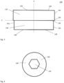
- FIG 3 schematically illustrates the cutting unit (120) being part of the cutting tool (100) illustrated in figure 1 .
- the cutting unit (120) comprises a cutting insert (122) and a shim (144), wherein the cutting insert (122) comprises an insert top surface (138), an insert bottom surface (140), and an insert side surface (142) connecting the insert top surface (138) and the insert bottom surface (140), wherein the shim (144) comprises a shim top surface (146), a shim bottom surface (148) and a shim side surface (150) connecting the shim top surface (146) and the shim bottom surface (148), wherein the shim top surface (146) is arranged in contact with the insert bottom surface (140), and wherein the cutting insert (122) and the shim (144) are rotationally fixed relative each other.
- the cutting unit (120) comprises a cutting unit bottom surface (128), a cutting unit top surface (130), and a cutting unit side surface (156) connecting the cutting unit bottom surface (128) and the cutting unit top surface (130).
- the shim bottom surface (148) constitutes the cutting unit bottom surface (128)
- the insert top surface (138) constitutes the cutting unit top surface (130).
- the shim side surface (150) together with the insert side surface (142) constitutes the cutting unit side surface (156).
- the cutting unit (120) comprises a central plane P extending midway between the cutting unit top surface (130) and the cutting unit bottom surface (128), and wherein the cutting unit (120) comprises a central axis A extending between the cutting unit top surface (130) and the cutting unit bottom surface (128) normal to the central plane P.
- Figure 4 schematically illustrates a bottom view of the cutting unit (120) illustrated in figure 3 .
- the cutting unit bottom surface (128) comprises an indexing interface (136) in form of an Allen key interface.
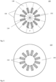
- Figure 5 schematically illustrates a top view of the cutting insert (122) being part of the cutting unit (120) as illustrated in figure 3 .
- the cutting insert (122) comprises a circular cutting edge (124) comprising twelve cutting edge portions (126).
- the insert top surface (138) comprises a plurality of cutting unit indexing elements (132,134) in form of twelve recesses in the insert top surface (138), wherein the distance between two neighboring recesses in the cutting unit top surface (130) is d in a circumferential direction around the central axis A.
- the cutting unit indexing elements (132,134) are configured to engage with the indexing indication elements (164,166), c.f. figure 8 .
- Figure 6 schematically illustrates a bottom view of the cutting insert (122) being part of the cutting unit (120) as illustrated in figure 3 .
- the insert bottom surface (140) comprises a plurality of insert support elements (152) in form of twelve recesses in the insert bottom surface.
- the insert support elements (152) are configured to engage with the shim support elements (154) arranged in the shim top surface (146), c.f. figure 7 .
- the cutting insert (122) is a double sided cutting insert, wherein the insert bottom surface (140) is identical to the insert top surface (138).
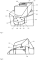
- Figure 7 schematically illustrates a top perspective view of the pocket (112) being part of the cutting tool (100) illustrated in figure 1 .
- the toolholder body (110) comprising a pocket (112) having a bottom support surface (114).
- the shim bottom surface (148) facing the bottom support surface (114).
- the shim top surface (146) comprises a plurality of shim support elements (154), which are configured to engage with the insert support elements (152) in the insert bottom surface (140).
- the toolholder body (110) comprises a first marking (118), wherein an extension of the first marking (118) in the direction of the central axis A intersects the plane Q.
- the shim side surface (150) comprises a second marking (158), wherein an extension of the second marking (158) in the direction of the central axis A intersects the plane Q.
- the clamp (160) comprises a clamp bottom surface (168) facing the toolholder body (110), and an opposite clamp top surface (170), wherein the clamping surface (162) is arranged at the clamp bottom surface (168), c.f.
- the clamp (160) comprises a through hole (176) extending from the clamp top surface (170) to the clamp bottom surface (168), wherein the through hole (176) is located between the front end surface (174) and the rear end surface (172) in the direction of the longitudinal axis B, wherein the fastening element (180) extends through the through hole (176), and wherein the resilient element (190) is arranged between the toolholder body (110) and the clamp bottom surface (168), wherein the resilient element (190) contacts the clamp bottom surface (168) between the rear end surface (172) and the through hole (176) in the direction of the longitudinal axis B.
- Figure 8 schematically illustrates a bottom perspective view of the pocket (112) being part of the cutting tool (100) illustrated in figure 1 .
- the clamp (160) comprises a plurality of indexing indication elements (164,166) in form of two protrusions extending from the clamping surface (162) in the direction towards the cutting unit (120).
- the indexing indication elements (164,166) are configured to engage with the cutting unit indexing elements (132,134), c.f. figure 5 .
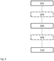
- Figure 9 schematically illustrates a flow chart of example method (200) steps for indexing the cutting edge (124) in the cutting tool illustrated in figure 1 .
- the method (200) comprises the steps of:
- the method (200) further comprises the steps of:
Landscapes
- Engineering & Computer Science (AREA)
- Mechanical Engineering (AREA)
- Cutting Tools, Boring Holders, And Turrets (AREA)
Priority Applications (2)
| Application Number | Priority Date | Filing Date | Title |
|---|---|---|---|
| EP22200705.6A EP4353386A1 (fr) | 2022-10-11 | 2022-10-11 | Outil de coupe comprenant un bord de coupe et procédé d'indexation d'un tel bord de coupe |
| PCT/EP2023/076513 WO2024078864A1 (fr) | 2022-10-11 | 2023-09-26 | Outil de coupe comprenant un bord de coupe et procédé d'indexage d'un tel bord de coupe |
Applications Claiming Priority (1)
| Application Number | Priority Date | Filing Date | Title |
|---|---|---|---|
| EP22200705.6A EP4353386A1 (fr) | 2022-10-11 | 2022-10-11 | Outil de coupe comprenant un bord de coupe et procédé d'indexation d'un tel bord de coupe |
Publications (1)
| Publication Number | Publication Date |
|---|---|
| EP4353386A1 true EP4353386A1 (fr) | 2024-04-17 |
Family
ID=83690192
Family Applications (1)
| Application Number | Title | Priority Date | Filing Date |
|---|---|---|---|
| EP22200705.6A Pending EP4353386A1 (fr) | 2022-10-11 | 2022-10-11 | Outil de coupe comprenant un bord de coupe et procédé d'indexation d'un tel bord de coupe |
Country Status (2)
| Country | Link |
|---|---|
| EP (1) | EP4353386A1 (fr) |
| WO (1) | WO2024078864A1 (fr) |
Citations (6)
| Publication number | Priority date | Publication date | Assignee | Title |
|---|---|---|---|---|
| GB1191063A (en) * | 1968-05-23 | 1970-05-06 | Rolls Royce | Tool Holder and Removable Cutting Insert |
| JP2009131915A (ja) * | 2007-11-29 | 2009-06-18 | Kyocera Corp | 切削工具および該切削工具を用いた切削方法 |
| DE102009049088A1 (de) | 2009-10-02 | 2011-04-07 | MAPAL Fabrik für Präzisionswerkzeuge Dr. Kress KG | Werkzeug zur spanenden Bearbeitung |
| US20130051941A1 (en) * | 2009-12-22 | 2013-02-28 | Raouf Ben Amor | Clamping system |
| US20140086694A1 (en) * | 2012-09-25 | 2014-03-27 | Kennametal Inc. | Double-sided cutting inserts with anti-rotation features |
| US20140356085A1 (en) * | 2013-05-30 | 2014-12-04 | Eines Canela S.A. | Multi-Clamp Insert and Toolholder Assembly |
-
2022
- 2022-10-11 EP EP22200705.6A patent/EP4353386A1/fr active Pending
-
2023
- 2023-09-26 WO PCT/EP2023/076513 patent/WO2024078864A1/fr not_active Ceased
Patent Citations (6)
| Publication number | Priority date | Publication date | Assignee | Title |
|---|---|---|---|---|
| GB1191063A (en) * | 1968-05-23 | 1970-05-06 | Rolls Royce | Tool Holder and Removable Cutting Insert |
| JP2009131915A (ja) * | 2007-11-29 | 2009-06-18 | Kyocera Corp | 切削工具および該切削工具を用いた切削方法 |
| DE102009049088A1 (de) | 2009-10-02 | 2011-04-07 | MAPAL Fabrik für Präzisionswerkzeuge Dr. Kress KG | Werkzeug zur spanenden Bearbeitung |
| US20130051941A1 (en) * | 2009-12-22 | 2013-02-28 | Raouf Ben Amor | Clamping system |
| US20140086694A1 (en) * | 2012-09-25 | 2014-03-27 | Kennametal Inc. | Double-sided cutting inserts with anti-rotation features |
| US20140356085A1 (en) * | 2013-05-30 | 2014-12-04 | Eines Canela S.A. | Multi-Clamp Insert and Toolholder Assembly |
Also Published As
| Publication number | Publication date |
|---|---|
| WO2024078864A1 (fr) | 2024-04-18 |
Similar Documents
| Publication | Publication Date | Title |
|---|---|---|
| EP0716895B2 (fr) | Une plaquette de tronçonnage ou de rainurage | |
| EP0291933B2 (fr) | Outil à tronçonner | |
| EP2070620B1 (fr) | Insert de découpe, outil de découpe utilisant cet insert, et procédé de découpe | |
| CN101687261B (zh) | 具有刀杆的锥齿轮的切削工具 | |
| US4552491A (en) | Cutting tool having cylindrical ceramic insert | |
| EP1879712B1 (fr) | Lame de separation de tournage avec partie de fixation a surfaces chanfreinees | |
| US5846032A (en) | Cutting insert and cutting tool | |
| US12434309B2 (en) | Milling cutter and blade part thereof | |
| EP4353386A1 (fr) | Outil de coupe comprenant un bord de coupe et procédé d'indexation d'un tel bord de coupe | |
| JPS5946723B2 (ja) | 穿孔工具 | |
| US4087194A (en) | Cutting tool | |
| US3646649A (en) | Grooving and cutoff tool | |
| EP2131984B1 (fr) | Insert de coupe indexable et procédé d'usinage | |
| EP3375552B1 (fr) | Outil de fraisage avec kit pour l'outil de fraisage | |
| JP6330963B1 (ja) | 刃先交換式バイト用ホルダ、および刃先交換式バイト用ホルダとレンチのセット | |
| CN221559849U (zh) | 一种机加工用扫刀 | |
| CN217941984U (zh) | 重切削铣刀盘 | |
| JP2000237904A (ja) | 旋削工具 | |
| EP4706852A1 (fr) | Insert de coupe et outil de coupe comprenant un tel insert de coupe | |
| CN217370505U (zh) | 一种具备伸缩限位保护的刀具 | |
| US20250296159A1 (en) | Milling tool | |
| EP0205886A2 (fr) | Fraise | |
| CN119053398A (zh) | 一种切削刀具 | |
| JP4940864B2 (ja) | スローアウェイ式回転工具及びこれに装着されるチップ | |
| KR200211403Y1 (ko) | 작은 구멍의 내경 가공을 위한 인덱서블 보링공구 |
Legal Events
| Date | Code | Title | Description |
|---|---|---|---|
| PUAI | Public reference made under article 153(3) epc to a published international application that has entered the european phase |
Free format text: ORIGINAL CODE: 0009012 |
|
| STAA | Information on the status of an ep patent application or granted ep patent |
Free format text: STATUS: THE APPLICATION HAS BEEN PUBLISHED |
|
| AK | Designated contracting states |
Kind code of ref document: A1 Designated state(s): AL AT BE BG CH CY CZ DE DK EE ES FI FR GB GR HR HU IE IS IT LI LT LU LV MC ME MK MT NL NO PL PT RO RS SE SI SK SM TR |
|
| STAA | Information on the status of an ep patent application or granted ep patent |
Free format text: STATUS: REQUEST FOR EXAMINATION WAS MADE |
|
| 17P | Request for examination filed |
Effective date: 20241017 |
|
| RBV | Designated contracting states (corrected) |
Designated state(s): AL AT BE BG CH CY CZ DE DK EE ES FI FR GB GR HR HU IE IS IT LI LT LU LV MC ME MK MT NL NO PL PT RO RS SE SI SK SM TR |