EP4353410A1 - Anfasmaschine mit automatischem vorschub - Google Patents
Anfasmaschine mit automatischem vorschub Download PDFInfo
- Publication number
- EP4353410A1 EP4353410A1 EP22200999.5A EP22200999A EP4353410A1 EP 4353410 A1 EP4353410 A1 EP 4353410A1 EP 22200999 A EP22200999 A EP 22200999A EP 4353410 A1 EP4353410 A1 EP 4353410A1
- Authority
- EP
- European Patent Office
- Prior art keywords
- attached
- rollers
- feed
- beveller
- main body
- Prior art date
- Legal status (The legal status is an assumption and is not a legal conclusion. Google has not performed a legal analysis and makes no representation as to the accuracy of the status listed.)
- Pending
Links
- 238000005520 cutting process Methods 0.000 claims abstract description 25
- 239000000463 material Substances 0.000 claims abstract description 17
- 239000002184 metal Substances 0.000 claims abstract description 16
- 230000005540 biological transmission Effects 0.000 claims abstract description 11
- 238000003754 machining Methods 0.000 claims abstract description 8
- 230000001939 inductive effect Effects 0.000 claims abstract description 5
- 229920003023 plastic Polymers 0.000 claims description 3
- 239000004033 plastic Substances 0.000 claims description 3
- 229920002635 polyurethane Polymers 0.000 claims description 3
- 239000004814 polyurethane Substances 0.000 claims description 3
- 239000004575 stone Substances 0.000 claims description 3
- 229910000831 Steel Inorganic materials 0.000 description 8
- 239000010959 steel Substances 0.000 description 8
- 238000010586 diagram Methods 0.000 description 2
- 230000001965 increasing effect Effects 0.000 description 2
- 238000000034 method Methods 0.000 description 2
- 230000000149 penetrating effect Effects 0.000 description 2
- 230000008092 positive effect Effects 0.000 description 2
- 238000003825 pressing Methods 0.000 description 2
- 239000003638 chemical reducing agent Substances 0.000 description 1
- 238000009434 installation Methods 0.000 description 1
- 230000001737 promoting effect Effects 0.000 description 1
- 238000003466 welding Methods 0.000 description 1
Images



Classifications
-
- B—PERFORMING OPERATIONS; TRANSPORTING
- B24—GRINDING; POLISHING
- B24B—MACHINES, DEVICES, OR PROCESSES FOR GRINDING OR POLISHING; DRESSING OR CONDITIONING OF ABRADING SURFACES; FEEDING OF GRINDING, POLISHING, OR LAPPING AGENTS
- B24B9/00—Machines or devices designed for grinding edges or bevels on work or for removing burrs; Accessories therefor
-
- B—PERFORMING OPERATIONS; TRANSPORTING
- B23—MACHINE TOOLS; METAL-WORKING NOT OTHERWISE PROVIDED FOR
- B23C—MILLING
- B23C3/00—Milling particular work; Special milling operations; Machines therefor
- B23C3/12—Trimming or finishing edges, e.g. deburring welded corners
-
- B—PERFORMING OPERATIONS; TRANSPORTING
- B23—MACHINE TOOLS; METAL-WORKING NOT OTHERWISE PROVIDED FOR
- B23Q—DETAILS, COMPONENTS, OR ACCESSORIES FOR MACHINE TOOLS, e.g. ARRANGEMENTS FOR COPYING OR CONTROLLING; MACHINE TOOLS IN GENERAL CHARACTERISED BY THE CONSTRUCTION OF PARTICULAR DETAILS OR COMPONENTS; COMBINATIONS OR ASSOCIATIONS OF METAL-WORKING MACHINES, NOT DIRECTED TO A PARTICULAR RESULT
- B23Q9/00—Arrangements for supporting or guiding portable metal-working machines or apparatus
- B23Q9/0007—Portable machines comprising means for their guidance or support directly on the workpiece
-
- B—PERFORMING OPERATIONS; TRANSPORTING
- B24—GRINDING; POLISHING
- B24B—MACHINES, DEVICES, OR PROCESSES FOR GRINDING OR POLISHING; DRESSING OR CONDITIONING OF ABRADING SURFACES; FEEDING OF GRINDING, POLISHING, OR LAPPING AGENTS
- B24B27/00—Other grinding machines or devices
- B24B27/0084—Other grinding machines or devices the grinding wheel support being angularly adjustable
-
- B—PERFORMING OPERATIONS; TRANSPORTING
- B24—GRINDING; POLISHING
- B24B—MACHINES, DEVICES, OR PROCESSES FOR GRINDING OR POLISHING; DRESSING OR CONDITIONING OF ABRADING SURFACES; FEEDING OF GRINDING, POLISHING, OR LAPPING AGENTS
- B24B49/00—Measuring or gauging equipment for controlling the feed movement of the grinding tool or work; Arrangements of indicating or measuring equipment, e.g. for indicating the start of the grinding operation
- B24B49/10—Measuring or gauging equipment for controlling the feed movement of the grinding tool or work; Arrangements of indicating or measuring equipment, e.g. for indicating the start of the grinding operation involving electrical means
Definitions
- the object of the invention is a beveller with automatic feed.
- An automatic beveller for steel pipes consisting of a frame, wherein there is a bevelling device at the two ends of the frame for bevelling the end part of the steel pipe, is known from the state of the art and disclosed in document CN201760673 .
- the bevelling device is located on a sliding rail stand which is provided with multiple roller guides for seating the steel pipe.
- the rollers are connected to each other via a guiding device which is driven by a stepper motor.
- the fully automatic beveller for steel pipes according to utility model can substantially relieve the operator's workload and has the functions of saving cost, promoting efficiency and increasing company profit.
- Document CN102689188 discloses a bevelling machine which is used to cut steel sheets and bevelling workpieces before welding, and in particular relates to the structure of the base of the bevelling machine.
- the base consists of a roller support, where four rollers are connected under the roller support; four bolts are arranged on the roller support in a penetrating manner; a backing plate is located on top of the roller support; each bolt is inserted into the backing plate in a penetrating manner and is connected by thread to the top nut and the bottom nut; each bottom nut is located between a padding plate and the roller support; each top nut is located above the padding plate; a thick spring and a thin spring are respectively located on each bolt; each thick spring is located between the padding plate and the bottom nut corresponding to the thick spring; and each thin spring is located between the padding plate and the top nut corresponding to the thin spring.
- the beveller When in operation, the beveller is mounted on the base and the rollers below the base roll forward under the gravitational action of the beveller, so that the automatic feed is achieved without affecting the length and weight of the plate; a The flexibility of the springs can allow the beveller to be automatically adjusted up and down.
- Document KR20160139714 discloses an automatic beveller for steel sheets.
- the automatic beveller for steel sheets consists of: a frame structure (100) which is formed by connecting a series of vertical and horizontal frames together; a chamfering section (200) which is attached to the frame structure (100); and pairs of roller tables (300a, 300b) which are connected to the front and rear ends of the chamfering section (200) to allow the steel sheet to be placed therein and discharged to the outside.
- Document KR20160055297 discloses an automatic chamfering machine which consists of: a main body which has a bottom plate, an outer wall and a cover; a horizontally movable frame which is formed in one inner side of the main body; an angle adjustment frame which is formed inside the horizontally movable frame; a fastening member which is coupled to a first fastening hole in the bottom part of the horizontally moving plate of the horizontally moving frame and a second fastening hole in the bottom part of the angle adjustment plate of the angle adjustment frame; a chamfering section which is formed inside the angle adjustment frame and has a chamfering cutter and a chamfering motor; a weight which is formed in the other inner side of the main body and maintains the weight balance; an automatic transmission section which is formed inside the main body and has a drive motor, reducer, multiple drive wheels and connecting members; a guiding roller section that is formed in the bottom part of the outer wall of the main body and has a roller and multiple rotating elements; and a dashboard that is formed
- the feed unit is provided with a control panel attached to the main body.
- the cutting unit comprises an electric motor which, via an angular transmission, drives a spindle on which the tool is fitted.
- a yoke together with a nut, a bolt and a holder connector, is attached to the angular transmission.
- each set of drive rollers and each set of pressure rollers consists of a conical roller and a cylindrical support roller, the axes of the conical rollers being horizontally offset from each other by 0.5 - 2°.
- an angular guide which connects to a set-block, is connected to a motor holder, the angular guide being provided with a movable locking key with a locking bolt screwed in.
- the rollers are made of plastic, in particular polyurethane.
- a plunge adjustment knob is attached to the motor holder, the former being connected to a lock which loosens a pressure stone by means of a tension member.
- control panel is attached to the main body of the feed unit via an extension arm.
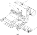
- FIG. 1 shows a beveller in an axonometric view
- Fig. 2 the beveller in an angled view from below
- Fig. 3 the interior of a cutting unit
- Fig. 4 sets of drive rollers and pressure rollers
- Fig. 5 an arrangement of the sets of drive rollers
- Fig. 6 - a diagram of a plunge adjustment system
- Fig. 7 - a diagram of a machining angle setting.
- a beveller with automatic feed composed of two main units:
- the feed unit (1) comprises a main body (3) which contains:
- Each set of drive rollers (5) and each set of pressure rollers consists of a conical roller (20) and a cylindrical support roller (21).
- Each of these rollers (20, 21) is made of plastic, in particular polyurethane, which, when pressed, adapts in shape to the surface being pressed, dampens the vibrations associated with the process, which has a positive effect on the components of the machine and increases the adhesion of the machine to the material being machined.
- the axes of the conical rollers (20) are horizontally offset from each other by 1° (similar results are obtained for an offset of 0.5 - 2°).
- the conical rollers (20) have the task of tensioning (pressing) the metal sheet during the installation of the beveller on the material to be machined, which results in increased rigidity.
- the arrangement of the conical rollers (20) as shown in figs 4 and 5 above allows the edge to be machined along its entire length without the use of additional guides.
- the feed unit is provided with a control panel (14), attached to the main body (3) of the feed unit (1) via an extension arm.
- a control panel (14) By means of the control panel (14), the operator activates the rotation of the cutting unit, selects the direction and adjusts the feed speed, and by means of a display, in a graphic form, receives information on: the load on the cutting unit motor, the feed direction, overloads, and the presence of the material to be machined.
- the cutting unit (2) comprises an electric motor (15) (single-phase with a power of 2200W) which, via an angular transmission (16), drives a spindle (17) on which the tool (cutting head) (18) is fitted, wherein a yoke (19), together with a nut, a bolt and a holder connector (27), is attached to the angular transmission (16).
- a yoke (19) together with a nut, a bolt and a holder connector (27), is attached to the angular transmission (16).
- the cutting unit is also characterised by an operator-safe method of changing the cutting head plunge, as well as by a system for securing the plunge setting.
- the plunge adjustment knob (22) is attached to the holder (11) of the motor (15). It can be used to set values after releasing a lock (23) which, by means of a tension member (24), loosens a pressure stone (25). This whole system ensures simple and safe operation at a distance from the working zone of the cutting head.
- the beveller according to the invention moves along the material to be machined and automatically stops at the ends of metal sheets (thanks to the inductive sensors assisting the operator).
- the conical drive rollers (20), which are set at an angle, ensure continuous contact between the front rollers and the front of the metal sheet on which they guide the beveller. As a result, the beveller produces an even chamfer. Constant and even guidance has a positive effect on the machining parameters.
- the roller axes are positioned perpendicular to the direction of travel and, as a result, an additional guide has usually been needed until now.
- the machine is able to machine the material while running in both directions. It is possible to machine any set angle from 70° to 0° (31) and from 0° to -70° (32).
- the machine can cut the material in both directions, without plunge correction.
- Any angle setting is possible thanks to an angular guide (28) which is connected to the holder (11) of the motor (15), and thanks to a set-block (29).
- a locking bolt (30) which is screwed into a locking key (34) movable in the angular guide (28)
- the operator can set the angle of the material to be machined in any manner.
- the beveller according to the invention is characterised by the following features:
Landscapes
- Engineering & Computer Science (AREA)
- Mechanical Engineering (AREA)
- Milling Processes (AREA)
Priority Applications (1)
| Application Number | Priority Date | Filing Date | Title |
|---|---|---|---|
| EP22200999.5A EP4353410A1 (de) | 2022-10-12 | 2022-10-12 | Anfasmaschine mit automatischem vorschub |
Applications Claiming Priority (1)
| Application Number | Priority Date | Filing Date | Title |
|---|---|---|---|
| EP22200999.5A EP4353410A1 (de) | 2022-10-12 | 2022-10-12 | Anfasmaschine mit automatischem vorschub |
Publications (1)
| Publication Number | Publication Date |
|---|---|
| EP4353410A1 true EP4353410A1 (de) | 2024-04-17 |
Family
ID=85685286
Family Applications (1)
| Application Number | Title | Priority Date | Filing Date |
|---|---|---|---|
| EP22200999.5A Pending EP4353410A1 (de) | 2022-10-12 | 2022-10-12 | Anfasmaschine mit automatischem vorschub |
Country Status (1)
| Country | Link |
|---|---|
| EP (1) | EP4353410A1 (de) |
Citations (7)
| Publication number | Priority date | Publication date | Assignee | Title |
|---|---|---|---|---|
| KR100773320B1 (ko) * | 2006-12-06 | 2007-11-05 | 이석재 | 모서리 가공장치 |
| EP1916057A1 (de) * | 2006-10-24 | 2008-04-30 | Cevisa Fabricaciones, S.L. | Anfasmaschine |
| CN201760673U (zh) | 2010-09-07 | 2011-03-16 | 上海天阳钢管有限公司 | 钢管全自动倒角机 |
| CN102689188A (zh) | 2012-05-30 | 2012-09-26 | 扬州宏承机械有限公司 | 自动坡口机的底座 |
| KR20160055297A (ko) | 2014-11-07 | 2016-05-18 | 유건이엔지 주식회사 | 이송수단을 구비하고 면취값 및 면취각도의 조절이 가능한 자동 면취기 |
| KR20160139714A (ko) | 2015-05-28 | 2016-12-07 | (주)에이티앤시코리아 | 철판 자동면취기 |
| KR101740864B1 (ko) * | 2016-07-18 | 2017-05-26 | 주식회사한현엔트 | 자동 면취기 |
-
2022
- 2022-10-12 EP EP22200999.5A patent/EP4353410A1/de active Pending
Patent Citations (7)
| Publication number | Priority date | Publication date | Assignee | Title |
|---|---|---|---|---|
| EP1916057A1 (de) * | 2006-10-24 | 2008-04-30 | Cevisa Fabricaciones, S.L. | Anfasmaschine |
| KR100773320B1 (ko) * | 2006-12-06 | 2007-11-05 | 이석재 | 모서리 가공장치 |
| CN201760673U (zh) | 2010-09-07 | 2011-03-16 | 上海天阳钢管有限公司 | 钢管全自动倒角机 |
| CN102689188A (zh) | 2012-05-30 | 2012-09-26 | 扬州宏承机械有限公司 | 自动坡口机的底座 |
| KR20160055297A (ko) | 2014-11-07 | 2016-05-18 | 유건이엔지 주식회사 | 이송수단을 구비하고 면취값 및 면취각도의 조절이 가능한 자동 면취기 |
| KR20160139714A (ko) | 2015-05-28 | 2016-12-07 | (주)에이티앤시코리아 | 철판 자동면취기 |
| KR101740864B1 (ko) * | 2016-07-18 | 2017-05-26 | 주식회사한현엔트 | 자동 면취기 |
Similar Documents
| Publication | Publication Date | Title |
|---|---|---|
| US4706481A (en) | Apparatus for cutting hollow pipe | |
| CN209334988U (zh) | 一种割管机 | |
| EP4353410A1 (de) | Anfasmaschine mit automatischem vorschub | |
| CA1228978A (en) | Apparatus for machining girders | |
| US5238339A (en) | Machine tool for working flat workpieces | |
| CN216829077U (zh) | 一种冲压模具生产用工件自动焊接装置 | |
| CN212793381U (zh) | 一种钢板切边机 | |
| US20120192689A1 (en) | Guide assembly and sheet material slitter incorporating the same | |
| CN210231867U (zh) | 一种螺旋焊管快速切割装置 | |
| CN220660012U (zh) | 一种方矩管切割机夹持装置 | |
| CN219523193U (zh) | 一种全自动可调式纸板开槽机 | |
| CN109807965B (zh) | 一种具有可调高压板机构的地板背部开槽设备 | |
| EP0462104B1 (de) | Vorrichtung und verfahren zur selektiven verformung eines dicken randes einer platte aus verformbarem material | |
| CN218135206U (zh) | 一种坡口机 | |
| CN217223858U (zh) | 一种剪板机送料装置 | |
| EP0921916B1 (de) | Apparat zum maschinellen bearbeiten von vertikalen tafeln | |
| CN117245132A (zh) | 一种钢结构加工用边口刨边机 | |
| CN108788311B (zh) | 钢板坡口机 | |
| CN211030288U (zh) | 一种应用于复合保温板生产线的可调式切割装置 | |
| JP2008012450A (ja) | 積層パネルの表層材の剥離装置 | |
| CN2132593Y (zh) | 多功能切割机 | |
| CN213318372U (zh) | 一种可快速锁定的双工位金属板激光切割平台 | |
| CN2249137Y (zh) | 切削式倒角机 | |
| CN212918601U (zh) | 一种机床用输送部件 | |
| CN214869598U (zh) | 管道自动切割装置 |
Legal Events
| Date | Code | Title | Description |
|---|---|---|---|
| PUAI | Public reference made under article 153(3) epc to a published international application that has entered the european phase |
Free format text: ORIGINAL CODE: 0009012 |
|
| STAA | Information on the status of an ep patent application or granted ep patent |
Free format text: STATUS: THE APPLICATION HAS BEEN PUBLISHED |
|
| AK | Designated contracting states |
Kind code of ref document: A1 Designated state(s): AL AT BE BG CH CY CZ DE DK EE ES FI FR GB GR HR HU IE IS IT LI LT LU LV MC ME MK MT NL NO PL PT RO RS SE SI SK SM TR |
|
| STAA | Information on the status of an ep patent application or granted ep patent |
Free format text: STATUS: REQUEST FOR EXAMINATION WAS MADE |
|
| 17P | Request for examination filed |
Effective date: 20241021 |