EP4353441B1 - Procédé et dispositif de contrôle d'un dispositif d'extrusion - Google Patents
Procédé et dispositif de contrôle d'un dispositif d'extrusion Download PDFInfo
- Publication number
- EP4353441B1 EP4353441B1 EP22201433.4A EP22201433A EP4353441B1 EP 4353441 B1 EP4353441 B1 EP 4353441B1 EP 22201433 A EP22201433 A EP 22201433A EP 4353441 B1 EP4353441 B1 EP 4353441B1
- Authority
- EP
- European Patent Office
- Prior art keywords
- tubular strand
- refractive index
- measuring
- measuring position
- measured
- Prior art date
- Legal status (The legal status is an assumption and is not a legal conclusion. Google has not performed a legal analysis and makes no representation as to the accuracy of the status listed.)
- Active
Links
Images


Classifications
-
- B—PERFORMING OPERATIONS; TRANSPORTING
- B29—WORKING OF PLASTICS; WORKING OF SUBSTANCES IN A PLASTIC STATE IN GENERAL
- B29C—SHAPING OR JOINING OF PLASTICS; SHAPING OF MATERIAL IN A PLASTIC STATE, NOT OTHERWISE PROVIDED FOR; AFTER-TREATMENT OF THE SHAPED PRODUCTS, e.g. REPAIRING
- B29C48/00—Extrusion moulding, i.e. expressing the moulding material through a die or nozzle which imparts the desired form; Apparatus therefor
- B29C48/25—Component parts, details or accessories; Auxiliary operations
- B29C48/92—Measuring, controlling or regulating
-
- B—PERFORMING OPERATIONS; TRANSPORTING
- B29—WORKING OF PLASTICS; WORKING OF SUBSTANCES IN A PLASTIC STATE IN GENERAL
- B29C—SHAPING OR JOINING OF PLASTICS; SHAPING OF MATERIAL IN A PLASTIC STATE, NOT OTHERWISE PROVIDED FOR; AFTER-TREATMENT OF THE SHAPED PRODUCTS, e.g. REPAIRING
- B29C48/00—Extrusion moulding, i.e. expressing the moulding material through a die or nozzle which imparts the desired form; Apparatus therefor
- B29C48/03—Extrusion moulding, i.e. expressing the moulding material through a die or nozzle which imparts the desired form; Apparatus therefor characterised by the shape of the extruded material at extrusion
- B29C48/09—Articles with cross-sections having partially or fully enclosed cavities, e.g. pipes or channels
-
- B—PERFORMING OPERATIONS; TRANSPORTING
- B29—WORKING OF PLASTICS; WORKING OF SUBSTANCES IN A PLASTIC STATE IN GENERAL
- B29C—SHAPING OR JOINING OF PLASTICS; SHAPING OF MATERIAL IN A PLASTIC STATE, NOT OTHERWISE PROVIDED FOR; AFTER-TREATMENT OF THE SHAPED PRODUCTS, e.g. REPAIRING
- B29C48/00—Extrusion moulding, i.e. expressing the moulding material through a die or nozzle which imparts the desired form; Apparatus therefor
- B29C48/25—Component parts, details or accessories; Auxiliary operations
- B29C48/30—Extrusion nozzles or dies
- B29C48/302—Extrusion nozzles or dies being adjustable, i.e. having adjustable exit sections
-
- B—PERFORMING OPERATIONS; TRANSPORTING
- B29—WORKING OF PLASTICS; WORKING OF SUBSTANCES IN A PLASTIC STATE IN GENERAL
- B29C—SHAPING OR JOINING OF PLASTICS; SHAPING OF MATERIAL IN A PLASTIC STATE, NOT OTHERWISE PROVIDED FOR; AFTER-TREATMENT OF THE SHAPED PRODUCTS, e.g. REPAIRING
- B29C48/00—Extrusion moulding, i.e. expressing the moulding material through a die or nozzle which imparts the desired form; Apparatus therefor
- B29C48/25—Component parts, details or accessories; Auxiliary operations
- B29C48/88—Thermal treatment of the stream of extruded material, e.g. cooling
- B29C48/90—Thermal treatment of the stream of extruded material, e.g. cooling with calibration or sizing, i.e. combined with fixing or setting of the final dimensions of the extruded article
- B29C48/901—Thermal treatment of the stream of extruded material, e.g. cooling with calibration or sizing, i.e. combined with fixing or setting of the final dimensions of the extruded article of hollow bodies
-
- B—PERFORMING OPERATIONS; TRANSPORTING
- B29—WORKING OF PLASTICS; WORKING OF SUBSTANCES IN A PLASTIC STATE IN GENERAL
- B29C—SHAPING OR JOINING OF PLASTICS; SHAPING OF MATERIAL IN A PLASTIC STATE, NOT OTHERWISE PROVIDED FOR; AFTER-TREATMENT OF THE SHAPED PRODUCTS, e.g. REPAIRING
- B29C48/00—Extrusion moulding, i.e. expressing the moulding material through a die or nozzle which imparts the desired form; Apparatus therefor
- B29C48/25—Component parts, details or accessories; Auxiliary operations
- B29C48/88—Thermal treatment of the stream of extruded material, e.g. cooling
- B29C48/911—Cooling
- B29C48/9115—Cooling of hollow articles
-
- G—PHYSICS
- G01—MEASURING; TESTING
- G01B—MEASURING LENGTH, THICKNESS OR SIMILAR LINEAR DIMENSIONS; MEASURING ANGLES; MEASURING AREAS; MEASURING IRREGULARITIES OF SURFACES OR CONTOURS
- G01B11/00—Measuring arrangements characterised by the use of optical techniques
- G01B11/02—Measuring arrangements characterised by the use of optical techniques for measuring length, width or thickness
- G01B11/06—Measuring arrangements characterised by the use of optical techniques for measuring length, width or thickness for measuring thickness ; e.g. of sheet material
- G01B11/0691—Measuring arrangements characterised by the use of optical techniques for measuring length, width or thickness for measuring thickness ; e.g. of sheet material of objects while moving
-
- G—PHYSICS
- G01—MEASURING; TESTING
- G01B—MEASURING LENGTH, THICKNESS OR SIMILAR LINEAR DIMENSIONS; MEASURING ANGLES; MEASURING AREAS; MEASURING IRREGULARITIES OF SURFACES OR CONTOURS
- G01B11/00—Measuring arrangements characterised by the use of optical techniques
- G01B11/08—Measuring arrangements characterised by the use of optical techniques for measuring diameters
- G01B11/10—Measuring arrangements characterised by the use of optical techniques for measuring diameters of objects while moving
- G01B11/105—Measuring arrangements characterised by the use of optical techniques for measuring diameters of objects while moving using photoelectric detection means
-
- G—PHYSICS
- G01—MEASURING; TESTING
- G01N—INVESTIGATING OR ANALYSING MATERIALS BY DETERMINING THEIR CHEMICAL OR PHYSICAL PROPERTIES
- G01N21/00—Investigating or analysing materials by the use of optical means, i.e. using sub-millimetre waves, infrared, visible or ultraviolet light
- G01N21/17—Systems in which incident light is modified in accordance with the properties of the material investigated
- G01N21/25—Colour; Spectral properties, i.e. comparison of effect of material on the light at two or more different wavelengths or wavelength bands
- G01N21/31—Investigating relative effect of material at wavelengths characteristic of specific elements or molecules, e.g. atomic absorption spectrometry
- G01N21/35—Investigating relative effect of material at wavelengths characteristic of specific elements or molecules, e.g. atomic absorption spectrometry using infrared light
- G01N21/3581—Investigating relative effect of material at wavelengths characteristic of specific elements or molecules, e.g. atomic absorption spectrometry using infrared light using far infrared light; using Terahertz radiation
-
- G—PHYSICS
- G01—MEASURING; TESTING
- G01N—INVESTIGATING OR ANALYSING MATERIALS BY DETERMINING THEIR CHEMICAL OR PHYSICAL PROPERTIES
- G01N21/00—Investigating or analysing materials by the use of optical means, i.e. using sub-millimetre waves, infrared, visible or ultraviolet light
- G01N21/17—Systems in which incident light is modified in accordance with the properties of the material investigated
- G01N21/41—Refractivity; Phase-affecting properties, e.g. optical path length
-
- B—PERFORMING OPERATIONS; TRANSPORTING
- B29—WORKING OF PLASTICS; WORKING OF SUBSTANCES IN A PLASTIC STATE IN GENERAL
- B29C—SHAPING OR JOINING OF PLASTICS; SHAPING OF MATERIAL IN A PLASTIC STATE, NOT OTHERWISE PROVIDED FOR; AFTER-TREATMENT OF THE SHAPED PRODUCTS, e.g. REPAIRING
- B29C2948/00—Indexing scheme relating to extrusion moulding
- B29C2948/92—Measuring, controlling or regulating
- B29C2948/92009—Measured parameter
- B29C2948/92114—Dimensions
- B29C2948/92123—Diameter or circumference
-
- B—PERFORMING OPERATIONS; TRANSPORTING
- B29—WORKING OF PLASTICS; WORKING OF SUBSTANCES IN A PLASTIC STATE IN GENERAL
- B29C—SHAPING OR JOINING OF PLASTICS; SHAPING OF MATERIAL IN A PLASTIC STATE, NOT OTHERWISE PROVIDED FOR; AFTER-TREATMENT OF THE SHAPED PRODUCTS, e.g. REPAIRING
- B29C2948/00—Indexing scheme relating to extrusion moulding
- B29C2948/92—Measuring, controlling or regulating
- B29C2948/92009—Measured parameter
- B29C2948/92114—Dimensions
- B29C2948/92152—Thickness
-
- B—PERFORMING OPERATIONS; TRANSPORTING
- B29—WORKING OF PLASTICS; WORKING OF SUBSTANCES IN A PLASTIC STATE IN GENERAL
- B29C—SHAPING OR JOINING OF PLASTICS; SHAPING OF MATERIAL IN A PLASTIC STATE, NOT OTHERWISE PROVIDED FOR; AFTER-TREATMENT OF THE SHAPED PRODUCTS, e.g. REPAIRING
- B29C2948/00—Indexing scheme relating to extrusion moulding
- B29C2948/92—Measuring, controlling or regulating
- B29C2948/92323—Location or phase of measurement
- B29C2948/92428—Calibration, after-treatment, or cooling zone
-
- B—PERFORMING OPERATIONS; TRANSPORTING
- B29—WORKING OF PLASTICS; WORKING OF SUBSTANCES IN A PLASTIC STATE IN GENERAL
- B29C—SHAPING OR JOINING OF PLASTICS; SHAPING OF MATERIAL IN A PLASTIC STATE, NOT OTHERWISE PROVIDED FOR; AFTER-TREATMENT OF THE SHAPED PRODUCTS, e.g. REPAIRING
- B29C2948/00—Indexing scheme relating to extrusion moulding
- B29C2948/92—Measuring, controlling or regulating
- B29C2948/92323—Location or phase of measurement
- B29C2948/92447—Moulded article
-
- B—PERFORMING OPERATIONS; TRANSPORTING
- B29—WORKING OF PLASTICS; WORKING OF SUBSTANCES IN A PLASTIC STATE IN GENERAL
- B29C—SHAPING OR JOINING OF PLASTICS; SHAPING OF MATERIAL IN A PLASTIC STATE, NOT OTHERWISE PROVIDED FOR; AFTER-TREATMENT OF THE SHAPED PRODUCTS, e.g. REPAIRING
- B29C2948/00—Indexing scheme relating to extrusion moulding
- B29C2948/92—Measuring, controlling or regulating
- B29C2948/92504—Controlled parameter
- B29C2948/92609—Dimensions
- B29C2948/92666—Distortion, shrinkage, dilatation, swell or warpage
-
- B—PERFORMING OPERATIONS; TRANSPORTING
- B29—WORKING OF PLASTICS; WORKING OF SUBSTANCES IN A PLASTIC STATE IN GENERAL
- B29C—SHAPING OR JOINING OF PLASTICS; SHAPING OF MATERIAL IN A PLASTIC STATE, NOT OTHERWISE PROVIDED FOR; AFTER-TREATMENT OF THE SHAPED PRODUCTS, e.g. REPAIRING
- B29C2948/00—Indexing scheme relating to extrusion moulding
- B29C2948/92—Measuring, controlling or regulating
- B29C2948/92504—Controlled parameter
- B29C2948/92704—Temperature
-
- B—PERFORMING OPERATIONS; TRANSPORTING
- B29—WORKING OF PLASTICS; WORKING OF SUBSTANCES IN A PLASTIC STATE IN GENERAL
- B29C—SHAPING OR JOINING OF PLASTICS; SHAPING OF MATERIAL IN A PLASTIC STATE, NOT OTHERWISE PROVIDED FOR; AFTER-TREATMENT OF THE SHAPED PRODUCTS, e.g. REPAIRING
- B29C2948/00—Indexing scheme relating to extrusion moulding
- B29C2948/92—Measuring, controlling or regulating
- B29C2948/92819—Location or phase of control
- B29C2948/92857—Extrusion unit
- B29C2948/92904—Die; Nozzle zone
Definitions
- the invention relates to a method for checking the setting of an extrusion device that produces a tubular strand that is conveyed along its longitudinal direction, wherein the outlet widths for extruded material are set differently on an upper side and on an underside of an extrusion nozzle of the extrusion device.
- the invention also relates to a device for carrying out the method.
- plastic pipes for supplying residential and industrial areas with gas and water, but also for drainage are mainly made from materials such as HDPE, PP and PVC.
- Typical pipe diameters are up to 3 m, with wall thicknesses of up to 250 mm.
- Production usually takes place in extrusion devices in which a plastic raw material is melted and extruded through a usually ring-shaped extrusion nozzle.
- the pipe extruded in this way is drawn lengthwise from the extrusion device and thus conveyed.
- the diameter of the drawn pipe is shaped to the desired outer diameter in a downstream calibration device, for example in the form of a sleeve.
- the pipe usually passes through several cooling sections in which the pipe is cooled and thus the initially still flowable plastic melt is gradually solidified.
- a first cooling section the formed pipe is prevented from collapsing, for example by means of a vacuum.
- the pipe is often cooled in the cooling sections using a cooling liquid, such as water.
- the cooling water flows around the pipe and quickly solidifies its outer area.
- the outer surface of the pipe is usually solidified, so that the outer geometry of the pipe does not change much.
- there are still parts of the pipe material inside the pipe wall that are still flowable.
- the pipe is then cut to the desired length using a flying saw.
- the shape of the pipe during the complete solidification after leaving the extrusion device is essentially influenced by two effects that must be taken into account in order to achieve, for example, a pipe wall thickness that is as uniform as possible. Firstly, there is shrinkage of the pipe material during cooling. Secondly, there is sagging, i.e. the sinking of the still flowable viscous mass components during solidification due to the influence of gravity.
- the extrusion nozzle of the extrusion device in an upper area with a larger exit width for extruded material than in a lower area.
- an exit gap of the extrusion nozzle can be set wider in the upper area than in a lower area.
- the extrusion nozzle can be heated more in an upper area than in a lower area, thereby realizing a larger exit width in the upper area than in the lower area of the extrusion nozzle. Both measures therefore ensure that more material exits the upper area of the extrusion nozzle than in the lower area.
- This intentionally asymmetrical application of the material is intended to compensate for sagging, so that the solidified pipe has as consistent a wall thickness as possible over its entire circumference.
- Important geometrical values of the pipe can only be measured after complete solidification, i.e. at the end of all cooling sections of the pipe, when the shrinkage and sagging are completely finished.
- a typical output of an extrusion device for medium pipe cross-sections is around 1,000 kg/h.
- the exit temperature of the melt from the extrusion nozzle is in the range of 200°C to 240°C, depending on the material.
- the first measurement results for the wall thickness and diameter are often only available hours after production has started.
- the outlet width in the upper area is set larger than in the lower area when setting the extrusion nozzle.
- the sagging is usually overcompensated, using empirical values. Ultimately, this leads to an unnecessary amount of material being discharged.
- WO 2022/058081 A1 A method is proposed for determining geometric parameters of a strand- or plate-shaped object, with which shrinkage is predicted. For this purpose, in a determination step, a relationship between the refractive index of the object and a shrinkage that occurs during its solidification is determined. In a determination step, the refractive index and at least one geometric parameter of the not yet fully solidified object are determined, in particular after a first cooling section of the object, and from the determined values, taking into account the relationship determined in the determination step, a geometric parameter in the fully solidified state of the object is calculated. The shrinkage of the material of the object during its solidification is therefore predicted and, on this basis, a geometric parameter, such as a wall thickness, is calculated in the fully solidified state of the object.
- a geometric parameter such as a wall thickness
- shrinkage can be reliably predicted and taken into account as one of the two effects that have a significant influence on the final geometry, whereby the measured values are advantageously available shortly after the material leaves the extrusion device and the final geometry parameter can be calculated accordingly early to avoid waste. Sagging, however, as the second significant effect on the final geometry of the object, cannot be predicted with the known method for reasons explained in more detail below.
- a method for determining the sagging of a pipe extruded in an extrusion device is known from WO 2022/106180 A1
- the wall thickness of the pipe is measured over the circumference of the pipe and a wall thickness curve is created over the circumference of the pipe from the measured wall thicknesses. Sagging of the melt is determined from the frequency and/or amplitude of the created wall thickness curve. While this method enables reliable detection of sagging, it is not possible to predict sagging using this method either.
- the invention is therefore based on the object of providing a method and a device of the type mentioned at the outset, with which the exit widths for extruded material set on the extrusion device can be reliably checked and, if necessary, corrected, taking into account the sagging of a tubular strand produced in an extrusion device, in particular in real time and with a small time offset after the strand exits the extrusion device.
- the invention also solves the problem by a device for carrying out the method according to the invention, comprising the terahertz measuring device and an evaluation device which is designed to check the ratio of the set exit widths for extruded material on the top and bottom of the extrusion nozzle.
- the sagging to be expected following the first measuring position i.e. the sagging of the still flowable, viscous mass fractions of the tubular strand emerging from the extrusion device during solidification due to the influence of gravity
- the tubular strand can be a pipe, for example a plastic pipe.
- the extrusion device has, in a manner known per se, an extrusion nozzle, for example a basically circular ring, from which the previously melted plastic material emerges.
- the tubular strand regularly passes through several cooling sections after exiting the extrusion device, in which the strand material is gradually cooled, for example by a cooling liquid such as water, until it cools down and thus completely solidifies.
- a cooling liquid such as water
- the outer surface of the tubular strand may already have solidified, so that the shaping of the outer surface of the tubular strand is complete.
- the material of the tubular strand still has recrystallizing areas and melt portions and is therefore at least partially still flowable, whereby as the strand cools further, as is known, sagging occurs in addition to shrinkage.
- shrinkage from the extrusion temperature to complete cooling is independent of the time course of solidification, in particular the cooling rate. Therefore, the shrinkage can be predicted in a simple and reliable manner by comparing the refractive index measured at the first measuring position with the cold value of the refractive index. Also, no significant influence can be exerted on the shrinkage by changing parameters such as the extrusion device or the cooling parameters. It is essentially an unchangeable process property, but it can be predicted relatively easily.
- a (first) terahertz measuring device is used at a first measuring position downstream of at least a first cooling section for the tubular strand, where the latter has not yet completely solidified, i.e. where it still has flowable recrystallizing and/or melt components, to measure, on the one hand, the average or resulting refractive index over the cross section of at least one wall thickness of the tubular strand and, on the other hand, also at the first measuring position, at at least two measuring locations on the top and bottom of the tubular strand, geometric values, including the wall thickness and/or the inner and/or outer diameter of the tubular strand, are measured.
- the terahertz measuring device comprises a terahertz transmitter and a terahertz detector, which are arranged essentially at the same location and can also be combined to form a transceiver in a particularly practical manner.
- the terahertz measuring radiation used according to the invention can, for example, be in a frequency range from 1 gigahertz to 6 terahertz.
- Terahertz radiation is well suited to difficult measuring conditions in the vicinity of extrusion devices, in particular with the high temperatures, possible contamination and the occurrence of steam and the like.
- terahertz radiation is largely insensitive to such interference.
- the terahertz radiation emitted by the transmitter of the terahertz measuring direction hits the tubular strand from above and/or below, for example. Part of the terahertz radiation is reflected on the outer surface of the strand and another part of the terahertz radiation enters the strand material. This leads to further reflections at the boundary surfaces of the tubular strand, in particular the boundaries of the wall sections of the strand facing and away from the transmitter. Part of the terahertz radiation also exits the strand on the side opposite the transmitter.
- the terahertz measuring device can have a reflector that reflects the terahertz radiation that has exited on the side of the strand facing away from the transmitter back to the strand, so that after further reflections at the boundary surfaces of the strand, it reaches the detector, which is arranged, for example, at the same location as the transmitter, together with the other radiation components reflected at the boundary surfaces, and is detected by the detector as a measurement event.
- the refractive index over the cross section of one or two opposite wall sections of the strand can be determined from the detected radiation, as will be explained in more detail below, at the first measuring position.
- the refractive index can be measured on the top and/or on the bottom of the strand.
- an average or resulting refractive index can be determined over both irradiated wall sections.
- the distances to the individual interfaces of the strand can be determined, from which in turn geometric parameters such as wall thicknesses and/or inner and/or outer diameters of the strand can be determined.
- the measurement on the top can, for example, be carried out at the highest point of the strand and the measurement on the bottom at the lowest point of the strand.
- the upper wall thickness and the lower wall thickness of the tubular strand can be measured at the first measuring position.
- a previously determined calibration relationship is used to predict the sagging that is still to be expected and to check the extrusion device.
- the basis for using the calibration relationship is the refractive index measured at the first measuring position.
- the calibration relationship assigns the refractive index at the first measuring position to the ratio of the set exit widths for extruded material on the top and bottom of the extrusion nozzle.
- the ratio of the exit widths on the top and bottom of the extrusion nozzle, as well as the ratio of the measured geometry values on the top and bottom of the strand can be given as a simple numerical ratio or, for example, as a percentage.
- the measured refractive index differs from its cold value.
- the measured value of the refractive index provides information about the flowable components still present inside the tubular strand at the first measuring position, in particular recrystallizing components and/or melt components.
- the calibration relationship provides - in particular for defined geometric parameters of the strand at the first measuring position and defined production parameters of the extrusion device - a correlation between the refractive index measured at the first measuring position and a ratio of the exit widths of the extrusion nozzle required for a desired strand geometry in the completely solidified state.
- This ratio of the exit widths resulting from the calibration relationship for the measured refractive index can be compared with the ratio of the set exit widths of the extrusion device in order to check the extrusion device.
- the exit width can be determined as described at the beginning. explained, for example, by setting an exit gap of the extrusion nozzle and/or by controlling heating devices of the extrusion nozzle. It is conceivable, for example, that the basic setting of the exit widths is carried out by setting the exit gap of the extrusion nozzle and a later fine adjustment or adjustment of the exit widths is then only carried out by controlling the heating devices of the extrusion nozzle.
- the prediction of the sagging to be expected downstream of the first measuring position and thus the checking of the extrusion device can be carried out quickly and in real time, so that, for example, the extrusion device can be controlled quickly in order to adjust the exit of the strand material from the extrusion nozzle, in particular at the top and bottom of the extrusion nozzle, so that the desired geometry of the strand is achieved in the completely solidified state.
- the desired geometry of a tubular strand is often a Cross-section should be circular geometry with constant wall thickness around the circumference.
- the calibration relationship can be stored in the form of a function or curve.
- the calibration relationship can be determined empirically in a particularly simple manner.
- the measured refractive index resulting at the first measuring position and the measured quotient of the geometry values, in particular the wall thicknesses, on the top and bottom can be stored.
- This stored refractive index can then be used to compare the refractive index measured at the first measuring position in a later process.
- the refractive index is known to be temperature-dependent.
- the measured refractive index deviates from the stored refractive index, it can be assumed that there is a change in the temperature and thus in particular in the still flowable parts inside the strand at the first measuring position. It can therefore be assumed that a correction of the set exit widths of the extrusion nozzle is necessary in order to achieve the desired geometry of the strand in the solidified state. As part of an empirical creation of the calibration context, further settings of the exit widths can be saved for different refractive indices at the first measuring position, which lead to the desired geometry of the strand in the solidified state.
- changes in the production parameters in the area before the first measuring position can have a significant influence on the sagging and thus the geometry of the strand in the solidified state.
- changes occur particularly when starting up a production process after a production stoppage.
- Examples include a temperature of the extrusion nozzle slowly increasing during start-up or a change in the output of the extrusion device.
- Another example is a change in the cooling parameters, for example due to a change in the composition and/or temperature of the coolant.
- Such changes can be detected not only from the refractive index measured at the first measuring position but also in particular from the geometry values measured at the first measuring position. This is particularly the case because a considerable part of the overall sagging has already occurred by the time the device leaves the first cooling section.
- it is therefore possible to set optimal process parameters, in particular of the extrusion device, particularly early on when a production process is restarted based on the calibration context.
- the calibration context for defined geometry values of the tubular strand is determined, for example, at the first measuring position. It can then further be provided that if a deviation of the geometry values measured at the first measuring position from the defined geometry values is detected, a warning is issued and/or the calibration context is adjusted according to the detected deviation of the geometry values.
- the calibration context can be adjusted by a factor corresponding to the detected change. This factor can be adjusted based on empirical values. be multiplied, for example, by a constant factor that takes into account the influence of the change on the sagging that occurs.
- material parameters of the tubular strand in particular the thermal conductivity and/or the heat capacity, can also be taken into account.
- Production parameters in particular the temperature of the extrusion nozzle and/or the withdrawal speed of the extrusion device and/or cooling parameters of the tubular strand produced, can also be taken into account. Such parameters also have an influence on the sagging that occurs.
- the calibration relationship can assign the refractive index at the first measuring position to a target ratio of the exit widths for extruded material on the top and bottom of the extrusion nozzle, so that the tubular strand has a target wall thickness profile, in particular a uniform wall thickness profile, over its circumference after it has completely solidified.
- the calibration relationship which is determined empirically, for example, can be in the form of a function or curve.
- the refractive index at the first measuring position can be plotted as a function of the ratio of the exit widths for extruded material on the top and bottom, which is to be set as the target ratio at the extrusion nozzle.
- the curve can be a straight line with a negative slope. However, it can also be a curve that deviates from a straight line.
- the extrusion device can be controlled, preferably automatically, to set the target ratio for the measured refractive index resulting from the calibration context.
- the control can be carried out by an evaluation device. This enables automatic control of the extrusion device.
- the target ratio can be displayed on an operator display for an operator.
- an expected sagging of the tubular strand until the tubular strand has completely solidified can be predicted.
- the predicted sagging and/or expected values of the measured geometry values in the completely solidified state of the tubular strand can then be displayed and/or the target ratio of the exit widths for extruded material on the top and bottom of the extrusion nozzle resulting from the calibration context can be adjusted based on the predicted sagging.
- the refractive index and/or the geometry values can be measured at the first measuring position at a large number of measuring locations over the circumference of the tubular strand.
- several terahertz transmitters and terahertz detectors can be arranged distributed over the circumference of the tubular strand.
- a terahertz measuring device rotating around the tubular strand with a terahertz transmitter and terahertz detector and, if necessary, a reflector can be provided, with which measured values can be generated distributed over the circumference. In particular, in this way, complete coverage of the circumference of the strand is conceivable in principle.
- the refractive index can be determined from a comparison of the transit time of the measuring radiation emitted by the terahertz measuring device without a tubular strand arranged in the beam path of the measuring radiation with the transit time of the measuring radiation with a tubular strand arranged in the beam path of the measuring radiation.
- This procedure for determining an unknown refractive index of an object is described, for example, in the EP 3 265 748 B 1.
- the refractive index determination using the terahertz measuring device can be carried out in a corresponding manner.
- the refractive index can be determined by using the terahertz measuring device to determine the optical wall thickness of the tubular strand, further by using the terahertz measuring device to determine an outer diameter and an inner diameter of the tubular strand, and by determining the refractive index of the tubular strand from a comparison of the determined outer and inner diameters with the determined optical wall thickness.
- This alternative way of determining an unknown refractive index is described in the DE 10 2018 128 248 A1 described. Again, this approach can be applied in this case.
- the geometry values of the tubular strand can be determined from a transit time measurement of measuring radiation emitted by the terahertz measuring device.
- the refractive index over the cross section of at least one wall of the tubular strand and/or the wall thickness and/or the inner and/or outer diameter of the tubular strand can be measured using a further terahertz measuring device at a second measuring position spaced apart from the first measuring position in the longitudinal direction of the tubular strand, in particular a second measuring position downstream of the first measuring position at which the tubular strand is essentially completely solidified.
- the wall thickness and/or the inner and/or outer diameter of the tubular strand on the top side of the tubular strand and the wall thickness on the bottom side of the tubular strand can be measured using the further terahertz measuring device.
- the calibration relationship can also be checked and corrected if necessary based on the measurement results of the further terahertz measuring device.
- the second measuring position can in principle be upstream or downstream of the first measuring position. It is preferably downstream, and in particular preferably so far downstream that the tubular strand is essentially completely solidified.
- the further terahertz measuring device can in principle be equipped in the same way as the (first) terahertz measuring device provided at the first measuring position.
- the further terahertz measuring device also has a (further) terahertz transmitter and a (further) terahertz detector, which in turn can be combined in a particularly practical manner to form a transceiver. Opposite the transmitter and possibly the detector arranged at the same location, a reflector can in turn be arranged on the opposite side of the tubular strand.
- the further terahertz measuring device can be arranged in a cost-effective manner at a fixed position, in particular in such a way that it emits terahertz measuring radiation onto the tubular strand from above vertically downwards or from below vertically upwards. It is also conceivable that the additional terahertz measuring device it is a portable measuring device, in particular a so-called handheld measuring device, which is therefore not permanently arranged at the second measuring position. The measurement of the refractive index and the aforementioned geometric parameters can in turn be carried out in the manner explained above for the terahertz measuring device arranged in the first measuring position.
- final material and geometric parameters of the strand can be measured, including the cold value of the refractive index.
- the measurement with another terahertz measuring device is much more accurate than, for example, a measurement with a mechanical probe.
- the final parameters measured at the second measuring position can be compared with the parameters of the calibration context and the calibration context can be verified and, if necessary, adjusted on the basis of the final parameters actually measured.
- the aforementioned design reduces the dependence on material parameters of the model according to the invention. Particularly in the area of plastic strands, the material parameters are often not known or defined with sufficient precision.
- an additional sensor can be used in the aforementioned design, for example to measure the cold value of the refractive index and the wall thickness at at least one angular position over the circumference of the strand or a ratio between at least two wall thicknesses at different angular positions, for example the ratio between the upper and lower wall thickness of the strand in the case of a terahertz measuring device fixed vertically above the strand.
- the calibration relationship used according to the invention can then be verified on the basis of the measured values of the further terahertz measuring device in order to reduce deviations caused by material parameters that deviate from reality, for example.
- the further terahertz measuring device can Any changes in the process temperature downstream of the first measuring position can be detected, which, as explained, have an influence on the sagging. An example is a change in the cooling rate of the strand.
- the volume or mass flow rate of the still flowable viscous material is approximately proportional to the sagging factor. With precise knowledge of the cold value of the refractive index, the sagging factor and thus the calibration relationship can be determined more precisely.
- the sagging factor at the respective measuring position represents an indicator from which it can be deduced to what extent the regularly deliberately set difference in the wall thickness emerging from the extrusion nozzle in the upper area and in the lower area will change in the further course of the extrusion line.
- the sagging factor SF at the measuring location of the terahertz measuring device can be preset so that the remaining sagging results in the desired, usually uniform wall thickness of the strand over the entire circumference.
- the calibration relationship further assigns the refractive index at the first measuring position to a ratio of the wall thicknesses on the top and bottom of the tubular strand at the first measuring position, wherein a weighting factor is applied to convert between the ratio of the wall thicknesses on the top and bottom of the tubular strand at the first measuring position and the target ratio of the exit widths for extruded material on the top and bottom of the extrusion nozzle, which takes into account a different degree of sagging upstream of the first measuring position and downstream of the first measuring position.
- a weighting can therefore be defined between the sagging of the strand that has already occurred, determined by measuring the geometry values at the first measuring position, and the sagging that is still to be expected until complete solidification.
- the sagging that has already occurred results from the comparison of the geometry values measured at the first measuring position with the exit widths set at the extrusion nozzle. If, for example, it is assumed that this will continue following the first measurement position, but to a lesser extent, the sagging that is still to be expected can be predicted by multiplying the sagging that has already occurred by a number less than 1, taking into account the refractive index measured at the first measurement position.
- a weighting factor can be formed that indicates the extent to which the sagging before the first measurement position is greater than the sagging after the first measurement position. For example, by forming a first quotient of the vertical gap dimensions of the extrusion nozzle in the upper and lower areas and a second quotient of the sagging at the first measurement position. Two quotients can be compared with each other based on the wall thicknesses measured in the upper and lower areas, for example a quotient can be formed from the first and second quotients. This can then form the weighting factor.
- the weighting factor will therefore generally be greater than 1.
- the weighting factor could be around 3.
- the usually desired uniform wall thickness of the strand over the circumference can be obtained on the basis of such a weighting factor.
- the refractive index at the first measuring position can be assigned in the calibration context either to the ratio of the wall thicknesses of the strand on its top and bottom measured at the first measuring position or to the target ratio of the exit widths on the top and bottom of the extrusion nozzle of the extrusion device.
- a further terahertz measuring device is provided at a second measuring position downstream of the first measuring position, its measured values can be used for fine adjustment of the model according to the invention and thus of the extrusion device.
- This third quotient which should ideally be 1, for example, can then be compared with the first and second quotients.
- a quotient could also be formed from the refractive index measured at the first measuring position and the (cold value of the) refractive index measured at the second measuring position.
- the measured values of the terahertz measuring device and, if applicable, the further terahertz measuring device are applied to the evaluation device.
- the evaluation device is designed to carry out the evaluation and checking according to the invention. It is also designed in particular to carry out the embodiments according to the dependent claims of the method according to the invention.
- the evaluation device can therefore comprise a control device, in particular for controlling the extrusion device, in particular the extrusion nozzle, in the manner explained above.
- the device can accordingly also comprise the further terahertz measuring device.
- the device can also comprise the extrusion device.
- a tubular strand 10 in this case a pipe 10, in particular a plastic pipe 10, is shown, which has a wall 12, a cavity 14 delimited by the pipe 10, an outer surface 16 with a circular cross-section and an inner surface 18, also circular in cross-section, which delimits the cavity 14.
- the pipe 10 is extruded with the aid of an extruder in an extrusion device 20 and conveyed along its longitudinal axis by means of a suitable conveyor device, in Figure 1 from left to right.
- the pipe 10 After leaving the extrusion nozzle of the extrusion device 20, which may be annular, the pipe 10 first passes through a first cooling section 22, in which the pipe 10, which is heated to a high degree and not yet completely solidified, i.e.
- the first cooling section 22 can comprise a calibration device, in particular a calibration sleeve, against which the tube 10 is pressed, for example by a vacuum and the normal pressure inside the tube 10. This finally determines the outer diameter of the tube 10 preformed by the extrusion nozzle.
- the tube 10 then passes through a first terahertz measuring device 24 in which the refractive index and geometric parameters of the tube 10, such as the inner and/or outer diameter and/or wall thickness, are determined in a manner explained in more detail below.
- the tube 10 passes through at least one further cooling section 26 in which further cooling takes place.
- the dashed lines on the tube 10 illustrate that further cooling sections 26 can be provided. After the pipe 10 has completely solidified, it is cut into predetermined sections in a cutting device 28, which may be a flying saw.
- the first terahertz measuring device 24 comprises a transceiver 30 in which a transmitter and a detector for terahertz radiation are combined.
- the transmitter emits terahertz radiation 32 onto the pipe 10.
- the terahertz radiation is reflected at different interfaces of the pipe 10 and at a reflector 34 arranged opposite the transceiver 30 and returns to the transceiver 30, where it is detected by the detector.
- the transceiver 30 is also connected to an evaluation device 38 via a line 36.
- the reflected radiation received by the detector generates corresponding measurement signals, which are passed on to the evaluation device 38 via the line 36.
- the evaluation device 38 can in this way, for example, Figure 2 marked wall thicknesses 40, 42 as well as the inner and/or outer diameter 44, for example based on transit time measurements.
- the evaluation device 38 can also determine the refractive index of the strand material on the basis of the measurement signals received from the detector, as is the case, for example, in the WO 2016/139155 A1 or DE 10 2018 128 248 A1 described.
- the first terahertz measuring device 24 is used to measure, for example, the outer diameter 44 and the wall thicknesses 40, 42 of the tube 10 as well as the refractive index at the Figure 1 shown first measurement position, where the pipe 10 is not yet completely solidified, i.e. still has flowable parts.
- the transceiver 30 can rotate along a circular path around the pipe 10, for example, and thus determine the geometric parameters and the refractive index at different locations around the circumference of the pipe 10.
- the reflector 34 can also rotate around the pipe 10. However, it is also possible to dispense with the reflector 34.
- the further terahertz measuring device 25 also comprises a transceiver 27 in which a transmitter and a detector for terahertz radiation are combined.
- a reflector 29 for terahertz radiation On an opposite side of the tube 10 there is again a reflector 29 for terahertz radiation. This reflects terahertz radiation 31 emitted by the transmitter after it has passed through the tube 10 and is reflected at the interfaces of the tube 10 back to the detector.
- the further terahertz measuring device 25 measures the refractive index and at least the wall thickness of the tube 10 on the top and bottom at a second measuring position at which the tube 10 is essentially completely solidified.
- the measurement of the refractive index and the geometry parameters, such as the inner and/or outer diameter and/or the The wall thickness of the tube 10 can be measured by the additional terahertz measuring device 25 at the Figure 1 shown second measuring position in the manner explained above for the first terahertz measuring device 24, in this case at a measuring position at which the pipe 10 is essentially completely solidified.
- the further terahertz measuring device 25 can be arranged in a fixed position in a particularly simple manner and only emit terahertz radiation vertically from above or below onto the pipe 10, so that the above-mentioned geometric parameters, in particular the wall thicknesses on the top and bottom of the pipe 10, are measured.
- the further terahertz measuring device 25 can also be a portable handheld device.
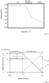
- Figure 3 shows the dependence of the refractive index on the temperature or the state of aggregation.
- the relationship between the refractive index and the temperature or the state of aggregation is non-linear.
- the refractive index changes particularly strongly in the recrystallization phase, i.e. at the transition between the solid and the liquid state of aggregation. This is used in the method according to the invention by using the measured refractive index to determine the remaining proportion of material in the recrystallization phase and, if applicable, in the liquid state, and from this to infer any sagging that is to be expected following the measurement at the first measuring position.
- the refractive index is plotted very schematically against the radial position x over the wall thickness.
- a range from 0 to 1 is plotted on the x-axis, with the wall thickness 0 corresponding to the outer surface and the value 1 to the inner surface of the considered wall of the tube 10.
- the values in Figure 4 Curve 46 shown as a solid line shows the refractive index. This is visible in the area of the solidified zone, i.e. in the range from about 0 to 0.4 on the x-axis, constant and corresponds to the cold value of the refractive index n cold , in this case for example 1.5. In the non-solidified zone, which follows radially inwards, the refractive index drops to a minimum value of about 1.46 in this case.
- a sagging factor SF k * ⁇ n, with a factor k, can be determined, the curve of which is Figure 4 is shown very schematically as a dashed line at the reference number 48.
- the sagging factor SF behaves essentially complementarily to the resulting refractive index n res .
- the actual course of the sagging factor SF can deviate from this linear course. The actual course can, for example, be determined empirically in a series of tests for the tubular strand produced in each case.
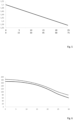
- Figure 5 shows an example of a calibration relationship used according to the invention. This assigns the refractive index at the first measuring position to a ratio of the exit widths at the top and bottom of the extrusion nozzle of the extrusion device 20 for extruded material.
- the refractive index is plotted on the y-axis at the first measuring position.
- the ratio of the wall thicknesses of the pipe 10 on its top and bottom, measured at the first measuring position i.e. the offset between the measured wall thicknesses on the top and bottom, is plotted in percent in the upper row.
- the corresponding target ratio of the exit widths on the top and bottom of the extrusion nozzle of the extrusion device 20, i.e. the offset between the exit widths on the top and bottom, is plotted in percent.
- the starting value 0% indicates a required difference of zero in the exit widths on the top and bottom of the extrusion nozzle and in the wall thicknesses measured at the top and bottom at the first measuring position, compared to 0. This is because in this purely theoretical case, no sagging is to be expected.
- the values in the upper row of the x-axis in Figure 5 indicate the difference (offset) between the wall thicknesses of the pipe 10 measured at the top and bottom at the first measuring position, which is required for the desired pipe geometry in the completely solidified state, at lower refractive indices, i.e. when the pipe 10 still has flowable parts.
- a value of 5% therefore means that the upper wall thickness is 5% greater than the lower wall thickness.
- a value of 10% accordingly means that the upper wall thickness is 10% greater than the lower wall thickness.
- the value given by the lower row of the x-axis in Figure 5 The corresponding required difference (offset) of the outlet widths at the top and bottom of the extrusion nozzle is obtained by multiplying the offset at the first measuring position by a value that reflects the different sagging upstream and downstream of the first measuring position, as explained above.
- the weighting factor takes into account the extent to which the sagging between the extrusion device 20 and the first measuring position is higher than the sagging that still occurs after the first measuring position.
- a weighting factor of 3 was assumed. This weighting factor can be determined empirically as explained.
- the calibration relationship can be determined empirically, for example, as explained above.
- the calibration relationship thus indicates the target ratio of the exit widths at the top and bottom of the extrusion nozzle of the extrusion device 20 for the refractive index of the pipe 10 measured at the first measuring position, which leads to a predetermined geometry of the pipe 10 in the completely solidified state, in particular to a uniform wall thickness over the circumference of the pipe 10.
- the refractive index decreases with increasing ratio between the exit widths at the top and bottom of the extrusion nozzle.
- Figure 6 shows, for illustration, the radial temperature profile within a wall of the pipe 10 from the inside to the outside for two different refractive indices measured at the first measuring position, as it results at the first measuring position of the first terahertz measuring device 24.
- the temperature is plotted in °C over the radial position, for example in mm.
- the solid curve corresponds to a larger measured refractive index than the dashed curve. Accordingly, the temperature profile shown by the dashed curve is higher than the temperature profile shown by the solid line.
- the temperature on the outside of the pipe has cooled down considerably and solidified due to the cooling liquid applied to the outside in the first cooling section 22.
- Figure 7 shows, for example, two different cases of wall thicknesses measured at the first measuring position over the circumference of the pipe 10, whereby the wall thickness of the pipe 10 in mm is plotted against the angular position in °. 180° is the top of the pipe and 0° or 360° the bottom.
- the dashed line corresponds, for example, to the Figure 6
- the dashed temperature distribution and the solid line corresponds, for example, to the Figure 6
- the temperature distribution shown in solid Figure 7 The curves shown were determined empirically and each lead to a uniform wall thickness over the circumference of the pipe 10.
- the ratio of the wall thicknesses at the top/bottom measured at the first measuring position must be 1.064, or 6.4% as a percentage of the offset.
- the refractive index over the cross section of at least one wall of the pipe 10 and geometric values, in particular the wall thickness and/or the inner and/or outer diameter of the pipe 10, are measured by means of the first terahertz measuring device 24 at the first measuring position immediately downstream of the first cooling section 22 at a plurality of measuring locations distributed over the circumference of the pipe 10, as explained above.
- the geometric values present at the first measuring position correspond to the geometric values for which the calibration relationship was created. If this is not the case, a warning can be issued or the calibration relationship can be changed, for example, by a factor corresponding to the deviation of the geometric values determined.
- the target ratio of the exit widths on the top and bottom of the extrusion nozzle of the extrusion device 20 resulting from the calibration relationship shown is determined by comparing the calibration relationship shown with the refractive index measured at the first measuring position and the geometry values measured at the first measuring position and compared with the actually set ratio of the exit widths on the top and bottom of the extrusion nozzle of the extrusion device 20. If these ratios deviate from one another, a warning can be issued and/or the extrusion device 20 can be controlled in such a way that the ratio of the exit widths on the top and bottom of the extrusion nozzle is adjusted to the target ratio resulting from the calibration relationship. This control of the extrusion device 20 can take place automatically.
- the measured values of the terahertz measuring device 24 are applied to the evaluation device 38.
- the evaluation device 38 can also display the Calibration context can be stored. The evaluation device 38 can carry out the explained evaluation and, if necessary, control the extrusion device 20.
- the additional terahertz measuring device 27 is also used to measure the refractive index and/or the wall thickness and/or the inner and/or outer diameter of the tube 10 at a second measuring position arranged downstream of the first measuring position, at which the tube 10 is essentially completely solidified.
- the additional terahertz measuring device 27 can measure the refractive index at the second measuring position, which can correspond in particular to the cold value of the refractive index, and the wall thickness of the tube 10 at least on its top and bottom.
- the measurement results of the additional terahertz measuring device 27 are also available at the evaluation device 38.
- the calibration relationship used as well as the cold value of the refractive index and the predicted sagging can be checked and, if necessary, corrected based on the actual parameters of the tube 10. This is done by the evaluation device 38. If necessary, the calibration relationship can be adjusted on this basis.
- the extrusion device 20 can be controlled on the basis of the evaluation of the measured values according to the invention and by using the calibration context by the evaluation device 38, which can comprise a corresponding control device for this purpose.
- the ratio of the exit widths for extruded material on the top and bottom of the extrusion nozzle of the extrusion device 20 can be adjusted by the evaluation device 38 as explained so that in the solidified state of the Pipe 10 results in the desired wall geometry of the pipe 10, in particular a wall thickness that is as uniform as possible over the circumference.
- the control device of the evaluation device 38 can, for example, adjust the gap width of the annular outlet gap of the extrusion nozzle on the top and bottom of the extrusion nozzle accordingly. It is also possible for the control device of the evaluation device 38 to influence heating elements of the extrusion nozzle in a suitable manner.
Landscapes
- Physics & Mathematics (AREA)
- Engineering & Computer Science (AREA)
- Mechanical Engineering (AREA)
- General Physics & Mathematics (AREA)
- Health & Medical Sciences (AREA)
- Biochemistry (AREA)
- Thermal Sciences (AREA)
- Analytical Chemistry (AREA)
- Life Sciences & Earth Sciences (AREA)
- General Health & Medical Sciences (AREA)
- Immunology (AREA)
- Pathology (AREA)
- Chemical & Material Sciences (AREA)
- Spectroscopy & Molecular Physics (AREA)
- Toxicology (AREA)
- Manufacturing & Machinery (AREA)
- Extrusion Moulding Of Plastics Or The Like (AREA)
- Investigating Or Analysing Materials By Optical Means (AREA)
- Length Measuring Devices By Optical Means (AREA)
Claims (18)
- Procédé de contrôle du réglage d'un dispositif d'extrusion (20) produisant un boudin tubulaire (10) transporté le long de sa direction longitudinale, dans lequel les largeurs de sortie pour le matériau extrudé sont réglés de façon différente sur un côté supérieur et sur un côté inférieur de la filière d'extrusion du dispositif d'extrusion, le procédé comportant les étapes suivantes :• l'indice de réfraction est mesuré sur la section transversale d'au moins une paroi du boudin tubulaire (10) au moyen d'un appareil de mesure térahertz (24), au niveau d'une première position de mesure en aval d'au moins un premier trajet de refroidissement (22) pour le boudin tubulaire (10), à laquelle le boudin tubulaire (10) n'est pas encore complètement solidifié,• des valeurs géométriques sont en outre mesurées à la première position de mesure, au moyen de l'appareil de mesure térahertz (24), au niveau d'au moins un point de mesure sur le côté supérieur et d'au moins un point de mesure sur le côté inférieur du boudin tubulaire (10), dans lequel les valeurs géométriques comportent l'épaisseur de paroi (40, 42) et/ou le diamètre intérieur et/ou extérieur (44) du boudin tubulaire (10),• pour l'indice de réfraction mesuré et pour un rapport des valeurs géométriques mesurées sur le côté supérieur et sur le côté inférieur du boudin tubulaire (10), le rapport des largeurs de sortie pour du matériau extrudé sur le côté supérieur et sur le côté inférieur de la filière d'extrusion est vérifié à l'aide d'une relation d'étalonnage déterminée préalablement entre l'indice de réfraction à la première position de mesure et le rapport des largeurs de sortie pour du matériau extrudé sur le côté supérieur et sur le côté inférieur de la filière d'extrusion.
- Procédé selon la revendication 1, caractérisé en ce que la relation d'étalonnage est déterminée pour des valeurs géométriques définies du boudin tubulaire (10).
- Procédé selon la revendication 2, caractérisé en ce que lors d'un écart constaté des valeurs géométriques mesurées à la première position par rapport à des valeurs géométriques définies, une alerte est émise et/ou la relation d'étalonnage est adaptée en fonction de l'écart constaté.
- Procédé selon l'une des revendications précédentes, caractérisé en ce que lors de la détermination de la relation d'étalonnage, des paramètres de matériau du boudin tubulaire (10), en particulier la conductivité thermique et/ou la capacité thermique, et/ou des paramètres de production, en particulier la température de la filière d'extrusion et/ou la vitesse d'enlèvement du dispositif d'extrusion (20) et/ou des paramètres de refroidissement du boudin tubulaire (10) fabriqué, sont pris en compte.
- Procédé selon l'une des revendications précédentes, caractérisé en ce que la relation d'étalonnage associe l'indice de réfraction à la première position de mesure à un rapport théorique des largeurs de sortie pour du matériau extrudé sur le côté supérieur et sur le côté inférieur de la filière d'extrusion, de telle façon que le boudin tubulaire (10) présente une évolution d'épaisseur de paroi théorique, en particulier une évolution d'épaisseur de paroi uniforme sur sa circonférence après sa solidification complète.
- Procédé selon la revendication 5, caractérisé en ce que lorsqu'un écart est constaté entre le rapport théorique des largeurs de sortie de la filière d'extrusion obtenu selon la relation d'étalonnage pour l'indice de réfraction mesuré à la première position de mesure et le rapport des largeurs de sortie réglées de la filière d'extrusion, le rapport théorique obtenu selon la relation d'étalonnage pour l'indice de réfraction mesuré est affiché et/ou en ce que le dispositif d'extrusion (20) est activé, de préférence automatiquement, pour le réglage du rapport théorique obtenu selon la relation d'étalonnage pour l'indice de réfraction mesuré.
- Procédé selon l'une des revendications 5 ou 6, caractérisé en ce que la relation d'étalonnage associe en outre l'indice de réfraction à la première position de mesure à un rapport des épaisseurs de paroi sur le côté supérieur et sur le côté inférieur du boudin tubulaire (10) à la première position de mesure, dans lequel, pour la conversion entre le rapport des épaisseurs de paroi sur le côté supérieur et sur le côté inférieur du boudin tubulaire (10) à la première position de mesure et le rapport théorique des largeurs de sortie pour du matériau extrudé sur le côté supérieur et sur le côté inférieur de la filière d'extrusion, un facteur de pondération est utilisé, lequel tient compte d'un degré d'affaissement différent en amont de la première position de mesure et en aval de la première position de mesure.
- Procédé selon l'une des revendications précédentes, caractérisé en ce qu'un affaissement attendu du boudin tubulaire (10) jusqu'à la solidification complète du boudin tubulaire (10) est prévu sur la base d'une comparaison des valeurs géométriques mesurées à la première position de mesure avec les largeurs de sortie réglées au niveau du dispositif d'extrusion (20).
- Procédé selon la revendication 8 et l'une des revendications 5 à 7, caractérisé en ce que l'affaissement prévu et/ou des valeurs attendues des valeurs géométriques mesurées à l'état complètement solidifié du boudin tubulaire (10) sont affichés et/ou en ce que le rapport théorique des largeurs de sortie pour du matériau extrudé sur le côté supérieur et sur le côté inférieur de la filière d'extrusion, obtenu selon la relation d'étalonnage, est adapté sur la base de l'affaissement prévu.
- Procédé selon l'une des revendications précédentes, caractérisé en ce que l'indice de réfraction est mesuré à la première position de mesure sur le côté supérieur et/ou le côté inférieur du boudin tubulaire (10).
- Procédé selon l'une des revendications précédentes, caractérisé en ce que l'indice de réfraction et/ou les valeurs géométriques sont mesurés en une pluralité de points de mesure sur la circonférence du boudin tubulaire (10).
- Procédé selon l'une des revendications 1 à 11, caractérisé en ce que l'indice de réfraction est déterminé à partir d'une comparaison du temps de propagation du rayonnement de mesure (32) émis par l'appareil de mesure térahertz (24) sans boudin tubulaire (10) disposé sur la trajectoire de faisceau du rayonnement de mesure (32) avec le temps de propagation du rayonnement de mesure (32) avec un boudin tubulaire (10) disposé sur la trajectoire de faisceau du rayonnement de mesure (32).
- Procédé selon l'une des revendications 1 à 11, caractérisé en ce que l'indice de réfraction est déterminé par détermination l'épaisseur de paroi optique (40, 42) du boudin tubulaire (10) à l'aide de l'appareil de mesure térahertz (24), ainsi que par détermination d'un diamètre extérieur (44) et d'un diamètre intérieur du boudin tubulaire (10) à l'aide de l'appareil de mesure térahertz (24), et par détermination de l'indice de réfraction du boudin tubulaire (10) à partir d'une comparaison des diamètres extérieur et intérieur (44) déterminés avec l'épaisseur de paroi optique (40, 42) déterminée.
- Procédé selon l'une des revendications précédentes, caractérisé en ce que les valeurs géométriques du boudin tubulaire (10) sont déterminées à partir d'une mesure de temps de propagation du rayonnement de mesure (32) émis par l'appareil de mesure térahertz (24).
- Procédé selon l'une des revendications précédentes, caractérisé en ce qu'au niveau d'une deuxième position de mesure espacée de la première position de mesure dans la direction longitudinale du boudin tubulaire (10), en particulier une deuxième position de mesure en aval de la première position de mesure, à laquelle le boudin tubulaire (10) est quasiment complètement solidifié, l'indice de réfraction sur la section transversale d'au moins une paroi du boudin tubulaire (10) et/ou l'épaisseur de paroi (40, 42) et/ou le diamètre intérieur et/ou extérieur (44) du boudin tubulaire (10) sont mesurés à l'aide d'un autre appareil de mesure térahertz (25).
- Procédé selon la revendication 15, caractérisé en ce qu'au niveau de la deuxième position de mesure, l'épaisseur de paroi (40, 42) et/ou le diamètre intérieur et/ou extérieur (44) du boudin tubulaire (10) sont mesurés sur le côté supérieur du boudin tubulaire (10) et sur le côté inférieur du boudin tubulaire (10) à l'aide de l'autre appareil de mesure térahertz (25).
- Procédé selon l'une des revendications 15 ou 16, caractérisé en ce que la relation d'étalonnage est vérifiée et si nécessaire corrigée à l'aide des résultats de mesure de l'autre appareil de mesure térahertz (25).
- Dispositif de mise en oeuvre du procédé selon l'une des revendications précédentes, comportant l'appareil de mesure térahertz (24) et un appareil d'évaluation (38), lequel est conçu pour vérifier le rapport des largeurs de sortie réglées pour du matériau extrudé sur le côté supérieur et sur le côté inférieur de la filière d'extrusion.
Priority Applications (7)
| Application Number | Priority Date | Filing Date | Title |
|---|---|---|---|
| ES22201433T ES3015088T3 (en) | 2022-10-13 | 2022-10-13 | Method and device for checking an extrusion device |
| PL22201433.4T PL4353441T3 (pl) | 2022-10-13 | 2022-10-13 | Sposób i przyrząd do sprawdzania urządzenia wytłaczającego |
| EP22201433.4A EP4353441B1 (fr) | 2022-10-13 | 2022-10-13 | Procédé et dispositif de contrôle d'un dispositif d'extrusion |
| JP2025520911A JP2025536902A (ja) | 2022-10-13 | 2023-08-14 | 押出装置の確認方法および押出装置 |
| CN202380072342.1A CN120035510A (zh) | 2022-10-13 | 2023-08-14 | 用于检查挤出装置的方法和设备 |
| KR1020257014908A KR20250087611A (ko) | 2022-10-13 | 2023-08-14 | 압출 장치 점검 방법 및 장치 |
| PCT/EP2023/072383 WO2024078777A1 (fr) | 2022-10-13 | 2023-08-14 | Procédé et dispositif de contrôle d'un appareil d'extrusion |
Applications Claiming Priority (1)
| Application Number | Priority Date | Filing Date | Title |
|---|---|---|---|
| EP22201433.4A EP4353441B1 (fr) | 2022-10-13 | 2022-10-13 | Procédé et dispositif de contrôle d'un dispositif d'extrusion |
Publications (3)
| Publication Number | Publication Date |
|---|---|
| EP4353441A1 EP4353441A1 (fr) | 2024-04-17 |
| EP4353441B1 true EP4353441B1 (fr) | 2024-12-18 |
| EP4353441C0 EP4353441C0 (fr) | 2024-12-18 |
Family
ID=83692781
Family Applications (1)
| Application Number | Title | Priority Date | Filing Date |
|---|---|---|---|
| EP22201433.4A Active EP4353441B1 (fr) | 2022-10-13 | 2022-10-13 | Procédé et dispositif de contrôle d'un dispositif d'extrusion |
Country Status (7)
| Country | Link |
|---|---|
| EP (1) | EP4353441B1 (fr) |
| JP (1) | JP2025536902A (fr) |
| KR (1) | KR20250087611A (fr) |
| CN (1) | CN120035510A (fr) |
| ES (1) | ES3015088T3 (fr) |
| PL (1) | PL4353441T3 (fr) |
| WO (1) | WO2024078777A1 (fr) |
Family Cites Families (7)
| Publication number | Priority date | Publication date | Assignee | Title |
|---|---|---|---|---|
| WO2016139155A1 (fr) | 2015-03-03 | 2016-09-09 | Sikora Ag | Dispositif et procédé de mesure du diamètre et/ou de l'épaisseur de paroi d'une barre de coulée |
| DE102018124175A1 (de) * | 2018-10-01 | 2020-04-02 | Sikora Ag | Verfahren und Vorrichtung zum Steuern einer Produktionsanlage für plattenförmige oder strangförmige Körper |
| DE102018128248B4 (de) | 2018-11-12 | 2023-03-30 | Sikora Ag | Verfahren zum Bestimmen des Brechungsindex eines rohrförmigen Körpers |
| CN114502351A (zh) * | 2019-10-10 | 2022-05-13 | 3M创新有限公司 | 用于吹塑膜厚度测量的方法和系统 |
| DE102020116810A1 (de) * | 2020-06-25 | 2021-12-30 | CiTEX Holding GmbH | THz-Messverfahren und THz-Messvorrichtung zum Vermessen eines Messobjektes, insbesondere eines Rohres |
| DE102020124263B4 (de) | 2020-09-17 | 2023-01-12 | Sikora Aktiengesellschaft | Verfahren zum Bestimmen mindestens eines Geometrieparameters eines strang- oder plattenförmigen Gegenstands |
| DE202020005512U1 (de) * | 2020-11-17 | 2021-09-15 | Sikora Aktiengesellschaft | Vorrichtung zum Ermitteln eines Absackens von Schmelze eines in einer Extrusionsvorrichtung extrudierten Rohrs |
-
2022
- 2022-10-13 EP EP22201433.4A patent/EP4353441B1/fr active Active
- 2022-10-13 ES ES22201433T patent/ES3015088T3/es active Active
- 2022-10-13 PL PL22201433.4T patent/PL4353441T3/pl unknown
-
2023
- 2023-08-14 WO PCT/EP2023/072383 patent/WO2024078777A1/fr not_active Ceased
- 2023-08-14 KR KR1020257014908A patent/KR20250087611A/ko active Pending
- 2023-08-14 CN CN202380072342.1A patent/CN120035510A/zh active Pending
- 2023-08-14 JP JP2025520911A patent/JP2025536902A/ja active Pending
Also Published As
| Publication number | Publication date |
|---|---|
| KR20250087611A (ko) | 2025-06-16 |
| JP2025536902A (ja) | 2025-11-12 |
| ES3015088T3 (en) | 2025-04-29 |
| PL4353441T3 (pl) | 2025-03-24 |
| WO2024078777A1 (fr) | 2024-04-18 |
| CN120035510A (zh) | 2025-05-23 |
| EP4353441C0 (fr) | 2024-12-18 |
| EP4353441A1 (fr) | 2024-04-17 |
Similar Documents
| Publication | Publication Date | Title |
|---|---|---|
| EP3861281B1 (fr) | Procédé et dispositif de commande d'une installation de production de corps en forme de plaques ou de torons | |
| EP4247615B1 (fr) | Procédé de détermination de l'affaissement d'une masse fondue d'un tube extrudé dans un dispositif d'extrusion | |
| EP3999308B1 (fr) | Procédé et dispositif de mesure d'une barre tubulaire | |
| EP0767148A1 (fr) | Procédé et appareil pour la fabrication des corps en verre par l'étirage d'une préforme | |
| WO2017000933A1 (fr) | Procédé et dispositif de détermination d'une propriété d'une couche dans un processus d'extrusion | |
| EP4214464B1 (fr) | Procédé de détermination d'au moins un paramètre géométrique d'un objet en forme de fil ou de plaque | |
| WO2017198262A1 (fr) | Procédé et ensemble pour réguler et commander des installations d'extrusion de tuyaux | |
| EP1969304A1 (fr) | Procede pour mesurer l'epaisseur de feuilles multicouches | |
| EP3628416B1 (fr) | Procédé et installation de coulée continue d'un produit métallique | |
| AT401031B (de) | Einrichtung zum regeln der wandstärke | |
| EP4353441B1 (fr) | Procédé et dispositif de contrôle d'un dispositif d'extrusion | |
| EP3658349B1 (fr) | Procédé et dispositif pour le contrôle de la fabrication d'un produit extrudé en matière plastique ainsi qu'installation d'extrusion pour l'extrusion d'un produit en matière plastique de ce type | |
| EP3526006B1 (fr) | Procédé de surveillance de la qualité d'une feuille mince et boudineuse | |
| DE2341127C2 (de) | Schlitzdüse zum Extrudieren eines thermoplastischen Kunststoffes | |
| DE102008052609B4 (de) | Verfahren zur Herstellung von Kunststoffhohlkörpern durch Blasformen | |
| EP4474129A1 (fr) | Dispositif et procédé de vérification du réglage d'un dispositif d'extrusion | |
| EP0693357B1 (fr) | Procédé de moulage de corps creux en matière thermoplastique par extrusion soufflage | |
| DE102015114637B3 (de) | Verfahren und Vorrichtung zum Herstellen eines mehrschichtigen Verbundrohres und Verbundrohr | |
| EP3307513B1 (fr) | Procédé de surveillance en ligne de la qualité d'une feuille et boudineuse pour feuilles pourvue d'un dispositif de surveillance en ligne de la qualité d'une feuille | |
| AT522497B1 (de) | Verfahren zum Herstellen eines Rohres, sowie Vorrichtung zum Durchführen des Verfahrens | |
| EP3877145B1 (fr) | Procédé et dispositif permettant de contrôler la fente de buse d'une buse de sortie d'une machine de production de feuilles plates | |
| EP4680448A1 (fr) | Méthode et machine d'extrusion de film pour la production d'un film plastique | |
| WO2004060637A1 (fr) | Procede de regulation de l'epaisseur de pellicules extrudees | |
| EP0218850A1 (fr) | Procédé de détermination d'un changement proportionnel d'un profil |
Legal Events
| Date | Code | Title | Description |
|---|---|---|---|
| PUAI | Public reference made under article 153(3) epc to a published international application that has entered the european phase |
Free format text: ORIGINAL CODE: 0009012 |
|
| STAA | Information on the status of an ep patent application or granted ep patent |
Free format text: STATUS: REQUEST FOR EXAMINATION WAS MADE |
|
| 17P | Request for examination filed |
Effective date: 20230707 |
|
| AK | Designated contracting states |
Kind code of ref document: A1 Designated state(s): AL AT BE BG CH CY CZ DE DK EE ES FI FR GB GR HR HU IE IS IT LI LT LU LV MC ME MK MT NL NO PL PT RO RS SE SI SK SM TR |
|
| P01 | Opt-out of the competence of the unified patent court (upc) registered |
Free format text: CASE NUMBER: APP_35088/2024 Effective date: 20240611 |
|
| GRAP | Despatch of communication of intention to grant a patent |
Free format text: ORIGINAL CODE: EPIDOSNIGR1 |
|
| STAA | Information on the status of an ep patent application or granted ep patent |
Free format text: STATUS: GRANT OF PATENT IS INTENDED |
|
| RIC1 | Information provided on ipc code assigned before grant |
Ipc: G01B 11/10 20060101ALN20240909BHEP Ipc: G01B 11/06 20060101ALN20240909BHEP Ipc: B29C 48/88 20190101ALI20240909BHEP Ipc: B29C 48/90 20190101ALI20240909BHEP Ipc: G01N 21/41 20060101ALI20240909BHEP Ipc: B29C 48/30 20190101ALI20240909BHEP Ipc: G01N 21/3581 20140101ALI20240909BHEP Ipc: B29C 48/09 20190101ALI20240909BHEP Ipc: B29C 48/92 20190101AFI20240909BHEP |
|
| INTG | Intention to grant announced |
Effective date: 20240918 |
|
| GRAS | Grant fee paid |
Free format text: ORIGINAL CODE: EPIDOSNIGR3 |
|
| GRAA | (expected) grant |
Free format text: ORIGINAL CODE: 0009210 |
|
| STAA | Information on the status of an ep patent application or granted ep patent |
Free format text: STATUS: THE PATENT HAS BEEN GRANTED |
|
| AK | Designated contracting states |
Kind code of ref document: B1 Designated state(s): AL AT BE BG CH CY CZ DE DK EE ES FI FR GB GR HR HU IE IS IT LI LT LU LV MC ME MK MT NL NO PL PT RO RS SE SI SK SM TR |
|
| REG | Reference to a national code |
Ref country code: CH Ref legal event code: EP |
|
| REG | Reference to a national code |
Ref country code: DE Ref legal event code: R096 Ref document number: 502022002427 Country of ref document: DE |
|
| REG | Reference to a national code |
Ref country code: IE Ref legal event code: FG4D Free format text: LANGUAGE OF EP DOCUMENT: GERMAN |
|
| U01 | Request for unitary effect filed |
Effective date: 20250107 |
|
| P04 | Withdrawal of opt-out of the competence of the unified patent court (upc) registered |
Free format text: CASE NUMBER: APP_2176/2025 Effective date: 20250114 |
|
| U07 | Unitary effect registered |
Designated state(s): AT BE BG DE DK EE FI FR IT LT LU LV MT NL PT RO SE SI Effective date: 20250116 |
|
| PG25 | Lapsed in a contracting state [announced via postgrant information from national office to epo] |
Ref country code: HR Free format text: LAPSE BECAUSE OF FAILURE TO SUBMIT A TRANSLATION OF THE DESCRIPTION OR TO PAY THE FEE WITHIN THE PRESCRIBED TIME-LIMIT Effective date: 20241218 |
|
| PG25 | Lapsed in a contracting state [announced via postgrant information from national office to epo] |
Ref country code: NO Free format text: LAPSE BECAUSE OF FAILURE TO SUBMIT A TRANSLATION OF THE DESCRIPTION OR TO PAY THE FEE WITHIN THE PRESCRIBED TIME-LIMIT Effective date: 20250318 |
|
| PG25 | Lapsed in a contracting state [announced via postgrant information from national office to epo] |
Ref country code: GR Free format text: LAPSE BECAUSE OF FAILURE TO SUBMIT A TRANSLATION OF THE DESCRIPTION OR TO PAY THE FEE WITHIN THE PRESCRIBED TIME-LIMIT Effective date: 20250319 |
|
| PG25 | Lapsed in a contracting state [announced via postgrant information from national office to epo] |
Ref country code: RS Free format text: LAPSE BECAUSE OF FAILURE TO SUBMIT A TRANSLATION OF THE DESCRIPTION OR TO PAY THE FEE WITHIN THE PRESCRIBED TIME-LIMIT Effective date: 20250318 |
|
| REG | Reference to a national code |
Ref country code: ES Ref legal event code: FG2A Ref document number: 3015088 Country of ref document: ES Kind code of ref document: T3 Effective date: 20250429 |
|
| PG25 | Lapsed in a contracting state [announced via postgrant information from national office to epo] |
Ref country code: SM Free format text: LAPSE BECAUSE OF FAILURE TO SUBMIT A TRANSLATION OF THE DESCRIPTION OR TO PAY THE FEE WITHIN THE PRESCRIBED TIME-LIMIT Effective date: 20241218 |
|
| PG25 | Lapsed in a contracting state [announced via postgrant information from national office to epo] |
Ref country code: IS Free format text: LAPSE BECAUSE OF FAILURE TO SUBMIT A TRANSLATION OF THE DESCRIPTION OR TO PAY THE FEE WITHIN THE PRESCRIBED TIME-LIMIT Effective date: 20250418 |
|
| PG25 | Lapsed in a contracting state [announced via postgrant information from national office to epo] |
Ref country code: SK Free format text: LAPSE BECAUSE OF FAILURE TO SUBMIT A TRANSLATION OF THE DESCRIPTION OR TO PAY THE FEE WITHIN THE PRESCRIBED TIME-LIMIT Effective date: 20241218 |
|
| PG25 | Lapsed in a contracting state [announced via postgrant information from national office to epo] |
Ref country code: CZ Free format text: LAPSE BECAUSE OF FAILURE TO SUBMIT A TRANSLATION OF THE DESCRIPTION OR TO PAY THE FEE WITHIN THE PRESCRIBED TIME-LIMIT Effective date: 20241218 |
|
| PGFP | Annual fee paid to national office [announced via postgrant information from national office to epo] |
Ref country code: PL Payment date: 20250901 Year of fee payment: 4 |
|
| PLBE | No opposition filed within time limit |
Free format text: ORIGINAL CODE: 0009261 |
|
| STAA | Information on the status of an ep patent application or granted ep patent |
Free format text: STATUS: NO OPPOSITION FILED WITHIN TIME LIMIT |
|
| REG | Reference to a national code |
Ref country code: CH Ref legal event code: L10 Free format text: ST27 STATUS EVENT CODE: U-0-0-L10-L00 (AS PROVIDED BY THE NATIONAL OFFICE) Effective date: 20251029 |
|
| REG | Reference to a national code |
Ref country code: CH Ref legal event code: U11 Free format text: ST27 STATUS EVENT CODE: U-0-0-U10-U11 (AS PROVIDED BY THE NATIONAL OFFICE) Effective date: 20251101 |
|
| U20 | Renewal fee for the european patent with unitary effect paid |
Year of fee payment: 4 Effective date: 20251016 |
|
| 26N | No opposition filed |
Effective date: 20250919 |
|
| PGFP | Annual fee paid to national office [announced via postgrant information from national office to epo] |
Ref country code: CH Payment date: 20251101 Year of fee payment: 4 |
|
| PGFP | Annual fee paid to national office [announced via postgrant information from national office to epo] |
Ref country code: ES Payment date: 20251114 Year of fee payment: 4 |