EP4353499A2 - Timon d'attelage - Google Patents
Timon d'attelage Download PDFInfo
- Publication number
- EP4353499A2 EP4353499A2 EP23202457.0A EP23202457A EP4353499A2 EP 4353499 A2 EP4353499 A2 EP 4353499A2 EP 23202457 A EP23202457 A EP 23202457A EP 4353499 A2 EP4353499 A2 EP 4353499A2
- Authority
- EP
- European Patent Office
- Prior art keywords
- drawbar
- connecting element
- towing
- trailer
- securing
- Prior art date
- Legal status (The legal status is an assumption and is not a legal conclusion. Google has not performed a legal analysis and makes no representation as to the accuracy of the status listed.)
- Pending
Links
Images


Classifications
-
- B—PERFORMING OPERATIONS; TRANSPORTING
- B60—VEHICLES IN GENERAL
- B60D—VEHICLE CONNECTIONS
- B60D1/00—Traction couplings; Hitches; Draw-gear; Towing devices
- B60D1/01—Traction couplings or hitches characterised by their type
- B60D1/02—Bolt or shackle-type couplings
-
- B—PERFORMING OPERATIONS; TRANSPORTING
- B60—VEHICLES IN GENERAL
- B60D—VEHICLE CONNECTIONS
- B60D1/00—Traction couplings; Hitches; Draw-gear; Towing devices
- B60D1/01—Traction couplings or hitches characterised by their type
- B60D1/02—Bolt or shackle-type couplings
- B60D1/025—Bolt or shackle-type couplings comprising release or locking lever pins
-
- B—PERFORMING OPERATIONS; TRANSPORTING
- B60—VEHICLES IN GENERAL
- B60D—VEHICLE CONNECTIONS
- B60D1/00—Traction couplings; Hitches; Draw-gear; Towing devices
- B60D1/14—Draw-gear or towing devices characterised by their type
- B60D1/143—Draw-gear or towing devices characterised by their type characterised by the mounting of the draw-gear on the towed vehicle
-
- B—PERFORMING OPERATIONS; TRANSPORTING
- B60—VEHICLES IN GENERAL
- B60D—VEHICLE CONNECTIONS
- B60D1/00—Traction couplings; Hitches; Draw-gear; Towing devices
- B60D1/14—Draw-gear or towing devices characterised by their type
- B60D1/167—Draw-gear or towing devices characterised by their type consisting of articulated or rigidly assembled bars or tubes forming a V-, Y- or U-shaped draw gear
-
- B—PERFORMING OPERATIONS; TRANSPORTING
- B60—VEHICLES IN GENERAL
- B60D—VEHICLE CONNECTIONS
- B60D1/00—Traction couplings; Hitches; Draw-gear; Towing devices
- B60D1/24—Traction couplings; Hitches; Draw-gear; Towing devices characterised by arrangements for particular functions
- B60D1/26—Traction couplings; Hitches; Draw-gear; Towing devices characterised by arrangements for particular functions for remote control, e.g. for releasing
Definitions
- the invention relates to a towing bar, via which a trailer can be coupled to a towing vehicle so that the trailer can be towed by the towing vehicle.
- Corresponding towing drawbars are usually used to ensure a power transfer between two vehicles, so that one vehicle can tow, pull or push the other vehicle.
- the towing vehicle is referred to as the towing vehicle and the towed vehicle is referred to as the trailer.
- the trailer does not have its own drive and is therefore dependent on movement by the towing vehicle.
- the trailer actually moves under its own power via a drive. can move, but it should still be moved by the towing vehicle. This can be the case, for example, if the vehicle's drive is defective and it must be towed by the towing vehicle.
- the towing bar In order to move the trailer over the towing vehicle, the towing bar must enable power transmission between the towing vehicle and the trailer.
- the towing bar is connected to the trailer on one side and can be detachably connected to the towing vehicle on the other side.
- the towing vehicle usually has a standardized interface such as a trailer coupling to connect the trailer to the towing vehicle via the towing bar.
- trailers that can only be pulled and pushed using the tow bar and that may have their own steering, but there are also trailers that can also be steered using the tow bar and therefore do not require their own steering. Especially when a trailer has multiple axles, it may be necessary to steer it in order to follow the towing vehicle when cornering. This is also known from cars that are being towed and where the towed car has to be actively positioned by a person. However, some trailers also allow the tow bar to be connected to a steering axle of the trailer so that the trailer follows the towing vehicle independently when cornering. This is known from a truck combination, for example.
- the invention sets itself the task of specifying a towing bar with which the trailer can be reliably decoupled from the towing vehicle in an emergency situation.
- the towing drawbar has two drawbar members, one of the drawbar members being connectable to the trailer and the other drawbar member being connectable to the towing vehicle, a connecting element being provided which connects the two drawbar members to one another in a connecting position and which is secured in the connecting position by a securing device, the connecting element being pre-tensioned into a release position which cancels the connection of the two drawbar members, and the securing of the connecting element being cancelable by actuating the securing device, so that the connecting element is automatically moved into the release position due to the pre-tensioning for the emergency decoupling of the trailer from the towing vehicle.
- the two drawbar links are connected to one another via a connecting element, so that power is transmitted between the towing vehicle and the trailer and the trailer can be pulled or pushed by the vehicle.
- the towing drawbar ensures that power flows from the towing vehicle via one drawbar link to the connecting element and from there to the other drawbar link and finally to the trailer or vice versa.
- the safety device secures or holds the connecting element in the connection position that connects the two drawbar links.
- the safety device therefore ensures that the two drawbar links are reliably connected via the connecting element, so that the drawbar links cannot accidentally separate from one another during normal operation and the flow of force is ensured.
- the connecting element is pre-tensioned in a release position that breaks the connection between the two drawbar links, so that in an emergency situation, the force required to separate the two drawbar links is already provided by the pre-tension and then only needs to be released.
- the pre-tension of the connecting element ensures that the two drawbar links can be separated from one another very quickly and without great additional effort.
- the pre-tensioning essentially causes the connecting element to suddenly move into the release position, in which the two drawbar links are no longer connected to one another via the connecting element and the trailer is therefore uncoupled from the towing vehicle. Due to the pre-tensioning force already provided during normal operation, the connecting element is automatically moved into the release position when it is unlocked.
- the drawbar link on the towing vehicle side can have connecting means for connection, in particular for detachable connection, to the towing vehicle.
- the drawbar link on the towing vehicle side can have an annular towing eye.
- the corresponding connecting means can be designed in such a way that the drawbar link can be connected to a conventional towing vehicle interface for coupling a trailer, such as a trailer coupling.
- the corresponding connecting means can be arranged on the end of the towing vehicle side drawbar link opposite the trailer side drawbar link and thus in the towing vehicle side end region of the towing drawbar.
- the trailer side drawbar link is hereinafter also referred to as the second drawbar link.
- the connecting element is designed as a connecting bolt.
- the design as a connecting bolt enables reliable power transmission between the two drawbar links in the connection position.
- the connecting element can be subjected primarily to shear stress.
- the connecting element can be designed primarily to withstand such stress.
- the connecting element can be made of steel, in particular high-alloy steel, in order to be able to withstand the corresponding requirements.
- the connecting element With regard to the alignment of the connecting element, it has proven to be advantageous if it extends vertically in the connection position.
- This design not only means that the pre-tensioning force acts on the connecting element, but also the force of gravity pushes the connecting element into the release position, which can ensure that the two drawbar links are reliably released.
- the vertical alignment of the connecting element also ensures that it reliably connects the two drawbar links to one another, even when driving over uneven terrain. This is because the vertical alignment means that the connecting element can also absorb torques around a transverse axis that extends parallel to the ground.
- the connecting element is secured against loss using a safety rope.
- a corresponding safety rope can ensure that the connecting element is not lost when being transferred to the release position, but remains connected to the towing drawbar via the safety rope even in the release position.
- the two drawbar links have been uncoupled from each other in an emergency, they can also be connected to each other again using the same connecting element.
- the connecting element is spring loaded in the release position is pre-tensioned.
- the spring can be designed as a helical spring and the pre-tensioning force can be dimensioned such that a reliable transfer of the connecting element from the connection position to the release position is ensured in the event of an emergency uncoupling of the trailer from the towing vehicle.
- the use of a leaf spring is also possible.
- the connecting element between the two drawbar links can be jammed, particularly if the trailer is jammed or caught and the towing vehicle is exerting a pulling force on the trailer. If the spring force, possibly in conjunction with gravity, is not large enough to move the connecting element into the release position, it can be sufficient to briefly remove the tension from the towing drawbar to release the connection and thus to provide emergency decoupling. This can happen, for example, due to load changes, for example due to jolting when driving due to uneven ground. Even when stationary, when the two drawbar links are largely free of force, emergency decoupling can be possible with little to no problem.
- the connecting element if the pre-tensioning force of the spring acts in the longitudinal direction of the connecting element.
- the connecting element can be moved in the axial direction from the connecting position to the release position by the pre-tensioning force of the spring acting in the longitudinal direction.
- the connecting element can extend essentially in the axial direction, so that the pre-tensioning force acts in the direction of the greatest geometric extension of the connecting element.
- the connecting element can be transferred in a linear direction from the connecting position to the release position. Such a In contrast to a rotary movement, for example, movement is less prone to errors.
- the connecting element has a shoulder that protrudes in the radial direction as a support for the spring.
- the force of the spring acting in the longitudinal or axial direction of the connecting element can be introduced into the connecting element via the shoulder, so that in the event of an emergency decoupling, the latter moves reliably into the release position.
- the spring is designed as a helical spring, the spring can surround the connecting element, so that the connecting element can be arranged within the spring. This ensures that the force is evenly distributed in the circumferential direction of the connecting element.
- the spring engages in one end region of the connecting element and the securing device in the opposite end region of the connecting element.
- the connecting element is particularly rigid and therefore not easily deformable, so that securing the end of the connecting element opposite the spring also ensures that the end is not moved due to the force of the spring.
- the spring can, for example, engage the lower end of the connecting element and the securing device can secure the connecting element at the upper end.
- the spring and the securing device are opposite each other with regard to the arrangement of the connecting element, which has also proven advantageous with regard to a compact structure.
- a drawbar link preferably at least one drawbar link
- the spring can thus be arranged on one side of the drawbar member and the safety element on the other side of the drawbar member.
- the spring can be supported at one end on the connecting element, in particular on the shoulder of the connecting element. At the opposite end, the spring can be supported on the outside of a drawbar member, in particular the first drawbar member.
- the spring can be arranged between the drawbar member, in particular between both drawbar members, and the shoulder of the connecting element.
- both drawbar members can also be arranged between the spring and the safety device, at least in sections.
- the connecting element can extend through the two drawbar members and be pre-tensioned at one end via the spring and secured at the other end via the safety device. This configuration allows the connecting element to be reliably secured and the two drawbar members to be reliably connected.
- the connecting element which is designed in particular as a bolt, can have a shaft section, in particular a cylindrical one, wherein the spring can be arranged at one end of the shaft section and the securing device at the other end of the shaft section.
- the securing element can extend through the connecting element, in particular the shaft section.
- the projection can be arranged at one end of the shaft section.
- the connecting element can define a longitudinal axis, which can be the axis of symmetry of the shaft section.
- the corresponding longitudinal axis can extend through the spring.
- the longitudinal axis can also extend through the securing element of the securing device.
- the longitudinal axis of the connecting element coincides with the longitudinal axis of the spring.
- the connecting element or the shaft section can extend through the spring or the spring can be on the connecting element or on the shaft section.
- the force of the spring can act in the longitudinal direction of the connecting element or the spring can be arranged in such a way that the force of the spring acts in the longitudinal direction of the connecting element. The spring cannot therefore exert any torque on the connecting element that could possibly lead to jamming.
- the two drawbar members each have a connecting area and the two connecting areas can be connected to one another, in particular by axially inserting one into the other.
- One of the drawbar members, in particular the second drawbar member can have a male connecting area and the other drawbar member, in particular the first drawbar member, can have a female connecting area, so that the two drawbar members can be inserted into one another accordingly.
- one drawbar member has a tubular cross-section and the other drawbar member can be axially inserted into this drawbar member.
- the first drawbar member has a tubular cross-section.
- the outer diameter of the inserted drawbar member can correspond to the inner diameter of the other drawbar member. This ensures that the two drawbar members cannot move against each other in the radial direction, but rather are positively connected to each other in the radial direction. If the two drawbar members are not yet connected to each other via the connecting element, they can move against each other in the axial direction. This mobility is then prevented by the connecting element.
- the connection area of the drawbar member, in particular of the second drawbar member can be designed in the manner of a axial projection which can be inserted into the connection area of the other drawbar member in the axial direction.
- the two drawbar links can thus be connected to one another in a form-fitting manner via the connecting element. This ensures a particularly reliable flow of power between the towing vehicle and the trailer via the towing drawbar or via the two drawbar links.
- the receptacles can each be arranged in an end connection area of the drawbar links.
- the connection areas can each be arranged in the end area of the drawbar link that faces the other drawbar link. With regard to the connecting means with the towing vehicle or the towing eye, the connection area can therefore be arranged in the end area opposite the connecting means.
- the mounts can be aligned when the drawbar links are inserted into one another, so that the connecting element can reach through the mounts of both drawbar links in the connected position.
- the connecting element can therefore extend through the two mounts and thereby ensure a positive connection of the two drawbar links. If the two drawbar links are pulled apart by a tensile force acting in the longitudinal direction, this is transferred via one of the two drawbar links to the connecting element, which is then essentially subjected to shear stress, and from there to the other drawbar link.
- the recordings it has proven to be advantageous if they have a free cross-section that is at least Diameter of the connecting element.
- This design enables the connecting element to be easily pushed through the two drawbar links, in particular by hand.
- the receptacles can be designed as through holes, the inner diameter of which can essentially correspond to the outer diameter of the connecting element. This also ensures that the connecting element does not become jammed when inserted.
- the two interconnected drawbar members are designed to be relatively rotatable relative to one another about a longitudinal axis.
- the relative rotatability ensures that the trailer can also be rotated relative to the towing vehicle about a corresponding longitudinal axis.
- a corresponding rotation about the longitudinal axis or such a torsion of the trailer relative to the towing vehicle is generally not necessary. This therefore only plays a role on uneven terrain with a certain transverse inclination.
- the corresponding relative rotatability thus prevents the towing drawbar from being damaged by high torsional forces or high torsional forces from the trailer being introduced into the towing vehicle or the towing vehicle interface.
- the corresponding longitudinal axis can extend centrally through the two drawbar members and be arranged parallel to the ground. Furthermore, the longitudinal axis can essentially correspond to the direction of travel when the towing vehicle is driving straight ahead.
- the drawbar link is designed to be fixed, as the interface for coupling the trailer to the towing vehicle does not allow any or only a very small rotation around a longitudinal axis.
- the second drawbar link can be designed to be fixed around the longitudinal axis relative to the trailer, but as the trailer can twist around the longitudinal axis relative to the towing vehicle, especially in the case of vehicles on uneven terrain with a transverse gradient, the two drawbar links can also twist against each other accordingly.
- the tubular drawbar link can function as a pivot bearing for the drawbar link inserted into the tubular drawbar link.
- the two drawbar members can be rotated relatively around the longitudinal axis within a predetermined angular range.
- the predetermined angular range ensures that torsional forces in the towing drawbar are kept to a minimum, but at the same time sufficient stability of the coupling of the trailer to the towing vehicle can be achieved so that the trailer cannot tip over, for example when driving over uneven terrain with a transverse gradient.
- the rotatability of the two drawbar members also ensures that the hole bearing forces are kept to a minimum so that they do not hinder the transfer of the connecting element from the connection position to the release position.
- the two drawbar links can be rotated relative to each other within an angular range of ⁇ 15 degrees, i.e. the trailer can rotate together with the drawbar link on the trailer side from the zero position by 15 degrees clockwise and 15 degrees anti-clockwise around the longitudinal axis. A total rotation of 30 degrees is therefore possible.
- the second drawbar link advantageously has corresponding tapers in the area of the mount.
- These can be designed as incisions, notches or milled outs, in particular as V-shaped incisions, notches or milled outs.
- the tapers could run in the direction of the center axis of the drawbar link, so that the free cross section increases from the center in a radial direction outwards.
- the smallest free cross section of the corresponding mount of the drawbar link can therefore be arranged in the middle, and this can correspond to the outer diameter of the connecting element.
- the cross section of the drawbar link can be designed to be axially symmetrical.
- the connecting element can be connected to the drawbar link on the vehicle in a rotationally fixed manner.
- the taper it has proven to be advantageous if it has two flanks that are arranged at an angle to each other.
- the two flanks are arranged symmetrically to each other, so that a symmetrical relative movement of the two drawbar members is ensured.
- the two flanks can, for example, form an angle of 30 degrees with each other, so that a relative movement of 15 degrees in each direction is possible.
- the flanks are advantageously designed to be straight.
- a flank of one taper meets a flank of the other taper at a contact point.
- This contact point can be arranged in the middle of the drawbar member and, since each taper can have two flanks, a left contact point and a right pivot point can be provided.
- the flanks are designed as stops that limit the relative rotation of the two drawbar members.
- the stops can therefore ensure that the two drawbar members can only be rotated relative to one another within a predetermined angular range. On the one hand, this ensures that the trailer has sufficient driving stability, but it also ensures that torsional forces occurring in the towing drawbar are kept within manageable limits.
- the connecting element together with one of the drawbar members, is relatively rotatable relative to the other drawbar member.
- the connecting element can thus be rotationally coupled to one drawbar member and then rotate together with it relative to the other drawbar member.
- the connecting member is advantageously rotationally coupled to the second drawbar member and then rotatable together with the second drawbar member relative to the first drawbar member about the longitudinal axis.
- the recess in the fixed drawbar member is designed in the form of an elongated hole, which allows a relative movement of the connecting element.
- the connecting element can thus be rotated together with one of the drawbar members and the connecting element can move back and forth in the elongated hole.
- the ends of the elongated hole can then act as stops to limit a relative rotation of the two drawbar members.
- the safety device With regard to the arrangement of the safety device, it has proven to be advantageous if it is arranged on the outside of one of the two drawbar links. This arrangement allows a very compact design. At the same time, the safety device can be easily accessed from the outside, which also enables easy maintenance of the safety device.
- the safety device it has also proven to be advantageous if it has a safety element that can be moved back and forth in a safety direction between a safety position and a release position.
- the safety element can be movable parallel to the longitudinal axis of the drawbar members. The movement between the safety position and the release position can therefore be arranged perpendicular to the movement of the connecting element between the connecting position and the release position.
- the safety element can be moved back and forth on the outside of one of the two drawbar members, in particular on the outside of the first drawbar member. When the safety device is actuated, the safety element can be transferred from the safety position to the release position.
- the force required to release the safety device is less than the pre-tensioning force acting on the connecting element.
- This design significantly reduces the force required to release the two drawbar links. This is because the pre-tensioning force required to move the connecting element from the connection position to the release position was already provided when the two drawbar links were connected via the connecting element, and in the event of an emergency uncoupling it is then only necessary to release this force by releasing the safety device.
- the pre-tensioning force required to drive out the connecting element is stored in the spring and can then be released by releasing the connecting element by activating the safety device in such a way that the connecting element is essentially suddenly released from the receptacles of the Drawbar links are pulled out and the positive connection between the two drawbar links is broken.
- the securing element it has proven advantageous if it is designed in a wedge shape.
- the wedge shape ensures that when the connecting element is released by moving the securing element from the securing position to the releasing position, the securing element cannot get caught or tilted. This is because even with a corresponding transfer, the connecting element can move to a certain extent in the direction of the release position due to the wedge shape. Due to the wedge shape, the securing element is preloaded in the direction of the releasing position due to the preload force of the spring, but does not move due to the friction between the securing element and the connecting element and/or between the securing element and the outside of the drawbar member. In the securing position, the securing element can at least partially cover the receptacles or at least the receptacle of a drawbar member, in particular the first drawbar member.
- the securing element blocks movement of the connecting element into the release position in the securing position.
- the connecting element is thus held in the connecting position by the securing element, which ensures a reliable connection of the two drawbar links.
- the connecting element has a recess, in particular a slot-shaped recess, in which the securing element is arranged in the securing position.
- This recess can be used to create a positive connection between the securing element and the connecting element.
- the recess can be complete connecting element extend parallel to the longitudinal axis. If the securing element is arranged in the recess or engages in it, vertical movement of the connecting element is not possible and it is therefore secured in the connecting position.
- the securing element can be of plate-shaped geometry and its thickness can be adapted to the width of the recess.
- the securing element can be pulled out of the recess in the connecting element.
- the securing element can be moved in a linear direction parallel to the longitudinal axis and after leaving the recess, the connecting element can then be moved independently from the recesses of the two drawbar links into the released position due to the pre-tensioning force.
- the directions of movement of the securing element and the connecting element are at a right angle to each other.
- the safety element is pre-tensioned into the safety position.
- the safety element can be pre-tensioned into the safety position via a spring.
- the securing element can be moved into the unlocked position against the pre-tensioning force of the spring.
- the spring force that pre-tensions the securing element into the locking position can be overcome and the securing element can be pulled into the unlocked position. If no force is exerted on the securing element, it moves in the direction of the locking position that secures the connecting element due to the pre-tensioning force.
- a pressure cylinder enables particularly simple movement of the safety element. If the pressure cylinder is pressurized with compressed air, the safety element can be pulled out of the recess in the connecting element so that it is released.
- the pressure cylinder can be designed as a compressed air cylinder. Alternatively, however, a hydraulically acting cylinder can also be provided which can be actuated with hydraulic fluid, in particular with oil.
- the pressure cylinder it has also proven advantageous if it has an interface for connection to a compressed air network or hydraulic network, particularly on the towing vehicle side.
- This design enables a very compact design, since the towing drawbar itself is not dependent on a compressor or on pressure.
- Military vehicles in particular usually have a compressed air network and/or a hydraulic network anyway.
- a corresponding compressed air network can therefore provide sufficient compressed air to move the pressure cylinder and thus to release the connecting element.
- a hydraulic network In order to pressurize the pressure cylinder with compressed air, for example, a solenoid valve can be opened from the interior of the vehicle so that compressed air can flow from a compressed air supply line to the pressure cylinder.
- the compressed air supply line can be constantly under pressure for this purpose.
- the pressure cylinder is designed to be remotely controlled.
- the pressure cylinder can therefore be operated from a safe distance, for example from inside the towing vehicle, and can be pressurized with compressed air or hydraulic fluid. It is therefore not necessary to that people would have to leave the towing vehicle to emergency uncouple the trailer from the towing vehicle.
- the safety element it has proven to be advantageous if it returns automatically to the safety position due to the pre-tension when the pressure cylinder is not pressurized with compressed air or hydraulic fluid.
- the connecting element can only be released via the safety device when the pressure cylinder is activated and pressurized with compressed air or hydraulic fluid. Unintentional emergency uncoupling can thus be prevented.
- the safety element of the safety device that releases the connecting element in the release position can also be moved by electromagnetic, mechanical or pyrotechnic actuation.
- the connecting element can then also be released in this way and then move independently from the connection position to the release position.
- a safety pin blocks movement of the safety element from the safety position to the release position.
- the pin can be arranged at the end of the safety element opposite the pressure cylinder, so that the pin and the pressure cylinder are opposite each other with respect to the connecting element.
- the pin prevents the safety element from being pulled out of the connecting element or the recess in the connecting element, so that the pin also prevents the trailer from being uncoupled from the towing vehicle.
- the pin In order to enable such uncoupling, the pin must first be removed, in particular by hand.
- the pin can prevent the towing bar from being accidentally triggered. This can be prevented, for example, if the trailer is being towed in peaceful territory and normal uncoupling of the trailer does not pose a risk.
- the split pin is removed and the safety device is activated so that the two drawbar links can be uncoupled from each other at any time in an emergency situation and also during the journey.
- one of the drawbar links has a drawbar fork, via which the drawbar link can be connected to the trailer.
- the drawbar fork can be part of the second drawbar link and the corresponding drawbar link can be connected to the trailer via this.
- the drawbar has two drawbar legs, each of which has a toothed segment at one end, via which the two drawbar legs are connected to one another in a movement-coupled manner.
- the two drawbar legs cannot therefore move independently of one another, but a movement of one drawbar leg can automatically lead to a movement of the other drawbar leg due to the coupling of the two toothed segments.
- This design ensures high stability and power transmission between the two drawbar legs. This is particularly advantageous when reversing or on tight bends, as the forces acting can be distributed between both drawbar legs.
- the toothed segments also prevent the towing bar or drawbar from buckling when the towing vehicle is pushing the trailer. The drawbar therefore acts as a rigid coupling with the trailer and does not provide an additional pivot point.
- drawbar it has also proven to be advantageous if tensile and compressive forces are distributed along the bisector of the fork angle of the drawbar. In this way, reliable power transmission can be ensured and the towing vehicle can move the trailer using both a pulling force and a pushing force.
- the drawbars can be connected to the trailer at the ends opposite the toothed segments.
- the connection to the trailer is advantageously rotatable so that no moments can be transferred between the trailer and the drawbars.
- the trailer can have corresponding interfaces for connecting to the drawbars. Since the two drawbars can be varied due to the possibility of movement via the toothed segments, the towing drawbar can also be adapted to different interfaces on a trailer.
- the drawbar has a holding element in which the two drawbar legs are mounted so that they can rotate.
- the two drawbar legs are advantageously mounted so that they can rotate in the area of the tooth segments.
- the holding element can comprise two plates, whereby one plate can be arranged above the tooth segments and the other plate below the tooth segments, so that the drawbar legs are mounted so that they can rotate between the two plates.
- the holding element can have a triangular or T-shaped design.
- the holding element it has proven to be advantageous if it is equipped with a support leg on the underside.
- the support leg can prevent the corresponding drawbar link from falling to the ground in the event of an emergency uncoupling and, in particular, the end connection area from being damaged. Due to the arrangement on the On the underside, only the support foot comes into contact with the ground, which is designed to bear the corresponding load.
- connection area of the drawbar link with the drawbar fork is arranged in the end area of the drawbar link opposite the drawbar legs.
- the corresponding drawbar link can therefore be connected to the trailer on one side via the drawbar legs and on the opposite side via the connection area with the other drawbar link or with the connection area of the other drawbar link.
- a trailer for a towing vehicle is also proposed, wherein the trailer is equipped with a towing bar which is designed in the manner described above. This results in the advantages already described above with regard to the towing bar.
- the towing drawbar is advantageously connected to a frame of the trailer so that no steering movement of the trailer is initiated via the drawbar.
- This simple construction is particularly advantageous when the trailer is designed as a tracked vehicle, as it does not necessarily have to have its own steering, but can be moved by the towing vehicle in curves without any problems.
- the trailer can be designed as a self-propelled vehicle or as a vehicle without a drive.
- the trailer can be a military vehicle, in particular a military tracked vehicle.
- a vehicle combination with a towing vehicle and a trailer is proposed, wherein the trailer is coupled to the towing vehicle via a towing drawbar and wherein the towing drawbar is This also results in the advantages already described with regard to the towing bar.
- the towing vehicle can have an interface for connection to the towing drawbar.
- This can be a conventional, in particular a standardized, interface via which a trailer can be coupled to the towing vehicle. If the trailer is to be uncoupled from the towing vehicle, the coupling between the towing drawbar and the towing vehicle can be released. In this respect, this corresponds to normal uncoupling.
- the emergency uncoupling of the towing drawbar described above, in which the two drawbar links are separated from one another, can only be used in an emergency situation. In the separated position, one drawbar link is then connected to the trailer and the other drawbar link to the towing vehicle.
- the towing vehicle can be a military vehicle, in particular a military wheeled or tracked vehicle.
- the trailer can be a vehicle, in particular a military vehicle, either with or without its own propulsion, a defective vehicle or, for example, a drone.
- a towing drawbar 10 is shown in a cut-away side view.
- the towing drawbar 10 is arranged on a trailer not shown in the illustration and can be used to couple the trailer to a towing vehicle pulling the trailer.
- the towing drawbar 10 has a towing eye 1.2 at one end, which in the top view of the Fig.4 can be seen.
- This towing eye 1.2 can be connected to a commercially available interface on the towing vehicle, so that the trailer is then coupled to the towing vehicle.
- the towing drawbar 10 or towing eye 1.2 can be uncoupled from the towing vehicle again and the towing vehicle can then be moved independently of the trailer.
- the towing drawbar 10 also offers the option of emergency decoupling, by means of which the trailer can be decoupled from the towing vehicle very quickly in an emergency situation, even while driving, and thus without manual intervention.
- the emergency decoupling is based on the fact that the towing drawbar essentially consists of three elements, namely a first drawbar element 1 on the towing vehicle side, a second drawbar element 2 on the trailer side Drawbar link 2 and a connecting element 3 that connects the two drawbar links 1, 2 in a form-fitting manner.
- the two drawbar links 1, 2 are connected to one another via the connecting element 3, so that the trailer can be pulled or towed by the towing vehicle and a power flow between the towing vehicle and the trailer is ensured via the towing drawbar 10. If the towing drawbar 10 is uncoupled in an emergency, the two drawbar links 1, 2 are separated from one another in the manner described in more detail below, so that the towing vehicle can then be moved independently of the trailer. After the emergency uncoupling, the first drawbar link 1 is still connected to the towing vehicle and the second drawbar link 2 is still connected to the trailer, but there is no longer any connection between the two drawbar links 1, 2. This emergency uncoupling function is described below with regard to the Fig.2 and 3 explained in more detail.
- the first drawbar member 1 on the towing vehicle side or its connecting area has a substantially tubular cross-section and the second drawbar member 2 on the trailer side or its connecting area is inserted into the first drawbar member 1 in the axial direction.
- the cross-sectional shape of the second drawbar member 2 is described below with regard to the Fig.1 will also be explained in more detail.
- the two drawbar links 1 can be moved against each other in the axial direction, i.e. along the longitudinal axis L.
- the longitudinal axis L corresponds to the central axis of the two drawbar links 1, 2 and this extends parallel to the ground in the direction of travel.
- the connecting element 3 designed as a bolt is pushed through the two drawbar links 1, 2 from below and these are thus connected to each other in a form-fitting manner via the connecting element 3.
- both drawbar links 1, 2 each have a receptacle 1.1, 2.1 designed as a bore.
- the two receptacles 1.2, 2.1 can be aligned when the two drawbar links 1, 2 are inserted into one another, so that when the two drawbar links 1, 2 are inserted together, a recess is formed that extends through the two drawbar links 1, 2.
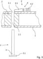
- This recess is also provided, for example, in the Fig.3 clearly visible. If the connecting element 3 is now inserted into this recess 3.2, the two drawbar links 1, 2 are reliably connected to one another via the connecting element 3.
- the connecting element 3 In order to separate the two drawbar links 1, 2 in an emergency situation, the connecting element 3 must be removed from the mounts 1.1, 1.2 and from the Fig.2 shown connection position V into the position shown in the Fig.3 shown release position F.
- the connecting element 3 connecting the two drawbar members 1, 2 is pre-tensioned by a spring 5 in the direction of the release position F.
- the spring 5, designed as a helical spring, is arranged between a radially projecting shoulder 3.1 of the connecting element 3 and the outside of the first drawbar member 1.
- the spring force acts perpendicular to the longitudinal axis downwards and aims to drive the connecting element 3 out of the receptacles 1.1, 2.1.
- the connecting element 3 is secured in the connection position V by a securing device 4, so that the pre-tensioning force does not lead to a movement of the connecting element 3.
- the safety device 4 securing the connecting element 3 must first be actuated or released.
- the safety device 4 essentially consists of two elements, namely a wedge-shaped safety element 4.1 and a pressure cylinder 4.2, which is connected to the safety element 4.1 via a rod.
- the securing device 4 is in a securing position S, ie the securing element 4.1 secures the connecting element 3 against movement into the release position F. This represents normal driving operation in which the trailer is coupled to the towing vehicle.
- the securing element 4.1 has a plate-shaped geometry and in the securing position S it engages in a slot-shaped recess 3.2 in the connecting element 3, or the securing element 4.1 penetrates the upper part of the connecting element 3 and thus prevents it from moving. There is also a positive connection between the securing element 4.1 and the connecting element 3 in the securing position S.
- the securing element 4.1 In order for the connecting element 3 to be driven by the spring 5 and move into the release position F to release the two drawbar links 1, 2 from each other, the securing element 4.1 must first be pulled out of the recess 3.2 of the connecting element 3, thereby removing the securing of the connecting element 3. In order to move the securing element 4.1 accordingly, the pressure cylinder 4.2 is pressurized with compressed air, which then pulls the securing element 4.1 from the securing position S into the unlocking position E against the force of a spring. The securing element 4.1 slides on the Outside of the first drawbar link 1 until it reaches the position shown in the Fig.3 has reached the release position E shown.
- the pressure cylinder 4.2 is connected to a vehicle-side pressure network via a corresponding interface and can, if required, be supplied with compressed air from inside the towing vehicle via a remote control.
- the securing element 4.1 is pulled out of the recess 3.2 of the connecting element 3, it is no longer secured.
- the spring force of the spring 5 can then develop and the connecting element 3 is essentially suddenly pressed downwards out of the two mounts 1.1, 2.1 and accelerated in the direction of the release position F.
- the spring 5 has then driven the connecting element 3 out of the mounts 1.1, 2.1 of the two drawbar links 1, 2, the two drawbar links 1, 2 can be moved axially towards each other and the flow of force between the towing vehicle and the trailer is eliminated.
- the towing drawbar 10 is then separated into two parts and the trailer is temporarily decoupled from the towing vehicle so that the towing vehicle can be moved independently of the trailer.
- the spring 5 pre-tensioning the connecting element 3 is already pre-tensioned when the two drawbar links 1, 2 are connected or when the connecting element 3 is inserted into the two receptacles 1.1, 2.1.
- the force required to release the two drawbar links 1, 2, by means of which the connecting element 3 can be moved into the release position P, is thus provided from the start and then only needs to be released for the emergency uncoupling of the trailer.
- the force for moving the securing element from the securing position S into the release position E is significantly lower than the pre-tensioning force acting on the connecting element 3 by the spring 5, so that in principle a A small impulse is sufficient to achieve reliable emergency decoupling.
- This is further supported by the wedge-shaped design of the securing element 4.1, since the securing element 4.1 can be pulled out of the recess 3.2 of the connecting element 3 with only a small amount of force due to the wedge shape.
- the cross-section of the second drawbar link 2 for example the connecting area of the second drawbar link 2, which can be connected to the first drawbar link 1, will now be explained in more detail.
- the outer diameter of the second drawbar link 2 corresponds approximately to the free inner diameter of the first drawbar link 1, so that the two drawbar links 1, 2 can only move slightly in the radial direction relative to one another after being plugged into one another.
- the mount 2.1 of the second drawbar link 2 is designed in such a way that the second drawbar link 2 can rotate relative to the first drawbar link 1 within certain limits even after being connected to the first drawbar link 1 by the connecting element 3.
- lateral tilting movements of the trailer which are to be feared on uneven terrain on a slope, for example, are not passed on directly to the vehicle, but rather the trailer can rotate back and forth about the longitudinal axis L together with the trailer-side drawbar link 2 within certain limits.
- This mobility reduces torsional forces and only transmits them to the vehicle from a certain angle of rotation.
- the second drawbar link 2 has two tapered portions 2.2 in the area of the holder 2.1, which are opposite one another with respect to a horizontal plane arranged parallel to the ground. These tapered portions 2.2 have the shape of a pointed notch which extends to the middle of the drawbar link. 2.
- the flanks 2.3 of the tapers 2.2 are straight and have an angle of approximately 15 degrees to the vertical central axis of the connecting element 3.
- the two flanks 2.3 of a taper 2.2 therefore have an angle of approximately 30 degrees to each other.
- the corresponding angle range W is also shown in the illustration of the Fig.1 shown.
- flanks 2.3 of the opposite tapers 2.2 which converge in the area of a horizontal and centrally arranged transverse axis, form an angle of approximately 150 degrees at the point of contact. Furthermore, the flanks 2.3 act as stops which limit the rotational movement of the two drawbar members 1, 2 relative to one another. As can be seen from the Fig.1 As can be seen, the two drawbar members 1, 2 can only be rotated relative to each other until the flanks 2.3 come into contact with the connecting element 3 and further rotation is prevented.
- FIG.4 shows the towing drawbar 10 in a top view, whereby the middle part of the towing drawbar 10, in which the two drawbar members 1, 2 are connected to each other, is not shown.
- the second drawbar link 2 has a drawbar 2.5, via which it is connected to the trailer.
- the drawbar 2.5 in turn consists essentially of two drawbar legs 2.6, which are connected to the trailer on one side and which have meshing tooth segments 2.7 on the other side.
- both drawbar legs 2.6 are rotatably mounted in a common holding element 2.8, which is essentially made up of two plates arranged parallel to one another, with one plate being arranged above the toothed segments 2.7 and the other plate being arranged below the toothed segments 2.7. Forces can thus be transmitted via the holding element 2.8 between the drawbar legs 2.6 on one side and the connecting area of the drawbar member 2 for connection to the first drawbar member 1 on the other side.
Landscapes
- Engineering & Computer Science (AREA)
- Transportation (AREA)
- Mechanical Engineering (AREA)
- Vehicle Cleaning, Maintenance, Repair, Refitting, And Outriggers (AREA)
- Handcart (AREA)
Applications Claiming Priority (1)
| Application Number | Priority Date | Filing Date | Title |
|---|---|---|---|
| DE102022126196.4A DE102022126196B4 (de) | 2022-10-10 | 2022-10-10 | Abschleppdeichsel, Anhänger sowie Fahrzeuggespann |
Publications (2)
| Publication Number | Publication Date |
|---|---|
| EP4353499A2 true EP4353499A2 (fr) | 2024-04-17 |
| EP4353499A3 EP4353499A3 (fr) | 2025-06-25 |
Family
ID=88297161
Family Applications (1)
| Application Number | Title | Priority Date | Filing Date |
|---|---|---|---|
| EP23202457.0A Pending EP4353499A3 (fr) | 2022-10-10 | 2023-10-09 | Timon d'attelage |
Country Status (2)
| Country | Link |
|---|---|
| EP (1) | EP4353499A3 (fr) |
| DE (1) | DE102022126196B4 (fr) |
Family Cites Families (11)
| Publication number | Priority date | Publication date | Assignee | Title |
|---|---|---|---|---|
| FR978266A (fr) * | 1948-12-28 | 1951-04-11 | Plumettaz & Co | Dispositif de dégagement pour les câbles tracteurs |
| DE1291213B (de) | 1963-09-03 | 1969-03-20 | Hornberger Eugen | Sicherung an Kupplungsbolzen von Fahrzeugen |
| DE1963460U (de) | 1967-04-26 | 1967-07-06 | Franz Peschler | Vorrichtung an transportwagen zum selbsttaetigen auskuppeln aus foerderschleppketten. |
| DE3532494A1 (de) | 1985-09-12 | 1987-03-19 | Paul Friese | Nasenbolzen |
| US5183284A (en) * | 1990-09-20 | 1993-02-02 | George Glenn Neis | Coupling mechanism |
| US5647604A (en) * | 1995-06-07 | 1997-07-15 | Russell; Gregory A. | Trailer hitch |
| US6047982A (en) * | 1998-04-20 | 2000-04-11 | New Holland North America, Inc. | Hitch for agricultural implement |
| DE10322933A1 (de) | 2003-05-21 | 2004-12-16 | Deere & Company, Moline | Sicherungsbolzen, Verriegelungseinrichtung und Zugelement |
| US8257014B2 (en) * | 2009-02-26 | 2012-09-04 | Miller Industries Towing Equipment Inc | Auto hook-up device for disabled vehicles |
| US8439388B1 (en) * | 2009-12-30 | 2013-05-14 | NSA RV Products Inc. | Universally pivotal tow bar assembly |
| US11376902B2 (en) * | 2019-06-13 | 2022-07-05 | Bar C Innovations LLC | Quick releasing hitch pin |
-
2022
- 2022-10-10 DE DE102022126196.4A patent/DE102022126196B4/de active Active
-
2023
- 2023-10-09 EP EP23202457.0A patent/EP4353499A3/fr active Pending
Also Published As
| Publication number | Publication date |
|---|---|
| EP4353499A3 (fr) | 2025-06-25 |
| DE102022126196A1 (de) | 2024-04-11 |
| DE102022126196B4 (de) | 2026-05-07 |
Similar Documents
| Publication | Publication Date | Title |
|---|---|---|
| DE886547C (de) | Mechanische Kupplungsvorrichtung | |
| EP3483004B1 (fr) | Dispositif de sauvetage pour un véhicule militaire | |
| DE3642044C2 (fr) | ||
| DE1036656B (de) | Hydraulische Lenkeinrichtung fuer hintereinander angeordnete Fahrwerke von Strassenfahrzeugen | |
| EP4353499A2 (fr) | Timon d'attelage | |
| DE202017106866U1 (de) | Dolly für Sattelauflieger | |
| DE1430224C3 (de) | Lösbare Zugvorrichtung zum Verbinden eines Anhängers mit einer Zugmaschine | |
| DE1014854B (de) | Sattelschlepperkupplung | |
| DE4343084C2 (de) | Vorrichtung zur lösbaren Verbindung von Fahrzeugen | |
| EP0319766A2 (fr) | Dispositif de couplage | |
| DE3512981A1 (de) | Kupplungswechselrahmen | |
| DE4427036C2 (de) | Vorrichtung zum lösbaren Verbinden eines Anhängers mit einem Zugfahrzeug | |
| DE1280064B (de) | Anhaengerkupplung fuer Kraftfahrzeuge | |
| DE3540641A1 (de) | Anhaengerkupplung - stichwort: "kupplungsmaulzentrierung am automatikgehaeuse" | |
| DE102020131617B4 (de) | Mobilkran umfassend einen Oberwagen mit wenigstens einer Lagerstelle zum Anbolzen eines Auslegers | |
| DE19721396C2 (de) | Vorrichtung zum stufenlosen Verstellen und Einstellen der Höhe einer Zuggabel an einem Anhänger | |
| DE102005057271B4 (de) | Kupplungsvorrichtung | |
| DE102016113800A1 (de) | Fahrzeuganhänger | |
| DE609107C (de) | Bremsvorrichtung mit zwei verschiedenen Bremsleistungen | |
| DE29721756U1 (de) | Bauhochkran, insbesondere untendrehender Baukran | |
| DE3939999A1 (de) | Kupplung | |
| DE19959176C2 (de) | Fahrwerk für weitausladende Arbeitsvorrichtungen | |
| AT237452B (de) | Gegen unbeabsichtigtes Öffnen gesicherte Anhängerkupplung für Kraftfahrzeuge | |
| DE3706258A1 (de) | Kupplungsanordnung an einem zugfahrzeug | |
| EP2500189B1 (fr) | Couplage mécanique pour un véhicule destiné à remorquer et pousser |
Legal Events
| Date | Code | Title | Description |
|---|---|---|---|
| PUAI | Public reference made under article 153(3) epc to a published international application that has entered the european phase |
Free format text: ORIGINAL CODE: 0009012 |
|
| STAA | Information on the status of an ep patent application or granted ep patent |
Free format text: STATUS: THE APPLICATION HAS BEEN PUBLISHED |
|
| AK | Designated contracting states |
Kind code of ref document: A2 Designated state(s): AL AT BE BG CH CY CZ DE DK EE ES FI FR GB GR HR HU IE IS IT LI LT LU LV MC ME MK MT NL NO PL PT RO RS SE SI SK SM TR |
|
| RAP3 | Party data changed (applicant data changed or rights of an application transferred) |
Owner name: KNDS DEUTSCHLAND GMBH & CO. KG |
|
| PUAL | Search report despatched |
Free format text: ORIGINAL CODE: 0009013 |
|
| AK | Designated contracting states |
Kind code of ref document: A3 Designated state(s): AL AT BE BG CH CY CZ DE DK EE ES FI FR GB GR HR HU IE IS IT LI LT LU LV MC ME MK MT NL NO PL PT RO RS SE SI SK SM TR |
|
| RIC1 | Information provided on ipc code assigned before grant |
Ipc: B60D 1/26 20060101ALI20250520BHEP Ipc: B60D 1/167 20060101ALI20250520BHEP Ipc: B60D 1/14 20060101ALI20250520BHEP Ipc: B60D 1/02 20060101AFI20250520BHEP |
|
| STAA | Information on the status of an ep patent application or granted ep patent |
Free format text: STATUS: REQUEST FOR EXAMINATION WAS MADE |
|
| 17P | Request for examination filed |
Effective date: 20251029 |