EP4353594A1 - Flugzeugsitz mit innerem sitzschalenrückstellfedermechanismus - Google Patents
Flugzeugsitz mit innerem sitzschalenrückstellfedermechanismus Download PDFInfo
- Publication number
- EP4353594A1 EP4353594A1 EP23202816.7A EP23202816A EP4353594A1 EP 4353594 A1 EP4353594 A1 EP 4353594A1 EP 23202816 A EP23202816 A EP 23202816A EP 4353594 A1 EP4353594 A1 EP 4353594A1
- Authority
- EP
- European Patent Office
- Prior art keywords
- seat
- stanchions
- seat pan
- attached
- aircraft
- Prior art date
- Legal status (The legal status is an assumption and is not a legal conclusion. Google has not performed a legal analysis and makes no representation as to the accuracy of the status listed.)
- Granted
Links
Images




Classifications
-
- B—PERFORMING OPERATIONS; TRANSPORTING
- B64—AIRCRAFT; AVIATION; COSMONAUTICS
- B64D—EQUIPMENT FOR FITTING IN OR TO AIRCRAFT; FLIGHT SUITS; PARACHUTES; ARRANGEMENT OR MOUNTING OF POWER PLANTS OR PROPULSION TRANSMISSIONS IN AIRCRAFT
- B64D11/00—Passenger or crew accommodation; Flight-deck installations not otherwise provided for
- B64D11/06—Arrangements of seats, or adaptations or details specially adapted for aircraft seats
-
- B—PERFORMING OPERATIONS; TRANSPORTING
- B60—VEHICLES IN GENERAL
- B60N—SEATS SPECIALLY ADAPTED FOR VEHICLES; VEHICLE PASSENGER ACCOMMODATION NOT OTHERWISE PROVIDED FOR
- B60N2/00—Seats specially adapted for vehicles; Arrangement or mounting of seats in vehicles
- B60N2/24—Seats specially adapted for vehicles; Arrangement or mounting of seats in vehicles for particular purposes or particular vehicles
- B60N2/30—Non-dismountable or dismountable seats storable in a non-use position, e.g. foldable spare seats
- B60N2/3038—Cushion movements
- B60N2/3063—Cushion movements by composed movement
- B60N2/3065—Cushion movements by composed movement in a longitudinal-vertical plane
-
- B—PERFORMING OPERATIONS; TRANSPORTING
- B64—AIRCRAFT; AVIATION; COSMONAUTICS
- B64D—EQUIPMENT FOR FITTING IN OR TO AIRCRAFT; FLIGHT SUITS; PARACHUTES; ARRANGEMENT OR MOUNTING OF POWER PLANTS OR PROPULSION TRANSMISSIONS IN AIRCRAFT
- B64D11/00—Passenger or crew accommodation; Flight-deck installations not otherwise provided for
- B64D11/06—Arrangements of seats, or adaptations or details specially adapted for aircraft seats
- B64D11/062—Belts or other passenger restraint means for passenger seats
-
- B—PERFORMING OPERATIONS; TRANSPORTING
- B64—AIRCRAFT; AVIATION; COSMONAUTICS
- B64D—EQUIPMENT FOR FITTING IN OR TO AIRCRAFT; FLIGHT SUITS; PARACHUTES; ARRANGEMENT OR MOUNTING OF POWER PLANTS OR PROPULSION TRANSMISSIONS IN AIRCRAFT
- B64D11/00—Passenger or crew accommodation; Flight-deck installations not otherwise provided for
- B64D11/06—Arrangements of seats, or adaptations or details specially adapted for aircraft seats
- B64D11/0639—Arrangements of seats, or adaptations or details specially adapted for aircraft seats with features for adjustment or converting of seats
- B64D11/064—Adjustable inclination or position of seats
-
- A—HUMAN NECESSITIES
- A47—FURNITURE; DOMESTIC ARTICLES OR APPLIANCES; COFFEE MILLS; SPICE MILLS; SUCTION CLEANERS IN GENERAL
- A47C—CHAIRS; SOFAS; BEDS
- A47C1/00—Chairs adapted for special purposes
- A47C1/12—Theatre, auditorium or similar chairs
-
- A—HUMAN NECESSITIES
- A47—FURNITURE; DOMESTIC ARTICLES OR APPLIANCES; COFFEE MILLS; SPICE MILLS; SUCTION CLEANERS IN GENERAL
- A47C—CHAIRS; SOFAS; BEDS
- A47C9/00—Stools for specified purposes
- A47C9/06—Wall stools
-
- B—PERFORMING OPERATIONS; TRANSPORTING
- B60—VEHICLES IN GENERAL
- B60N—SEATS SPECIALLY ADAPTED FOR VEHICLES; VEHICLE PASSENGER ACCOMMODATION NOT OTHERWISE PROVIDED FOR
- B60N2/00—Seats specially adapted for vehicles; Arrangement or mounting of seats in vehicles
- B60N2/24—Seats specially adapted for vehicles; Arrangement or mounting of seats in vehicles for particular purposes or particular vehicles
- B60N2/30—Non-dismountable or dismountable seats storable in a non-use position, e.g. foldable spare seats
- B60N2/3002—Non-dismountable or dismountable seats storable in a non-use position, e.g. foldable spare seats back-rest movements
- B60N2/302—Non-dismountable or dismountable seats storable in a non-use position, e.g. foldable spare seats back-rest movements by translation only
- B60N2/3027—Non-dismountable or dismountable seats storable in a non-use position, e.g. foldable spare seats back-rest movements by translation only along vertical axis
-
- B—PERFORMING OPERATIONS; TRANSPORTING
- B64—AIRCRAFT; AVIATION; COSMONAUTICS
- B64D—EQUIPMENT FOR FITTING IN OR TO AIRCRAFT; FLIGHT SUITS; PARACHUTES; ARRANGEMENT OR MOUNTING OF POWER PLANTS OR PROPULSION TRANSMISSIONS IN AIRCRAFT
- B64D11/00—Passenger or crew accommodation; Flight-deck installations not otherwise provided for
- B64D11/06—Arrangements of seats, or adaptations or details specially adapted for aircraft seats
- B64D11/0619—Arrangements of seats, or adaptations or details specially adapted for aircraft seats with energy absorbing means specially adapted for mitigating impact loads for passenger seats, e.g. at a crash
-
- B—PERFORMING OPERATIONS; TRANSPORTING
- B64—AIRCRAFT; AVIATION; COSMONAUTICS
- B64D—EQUIPMENT FOR FITTING IN OR TO AIRCRAFT; FLIGHT SUITS; PARACHUTES; ARRANGEMENT OR MOUNTING OF POWER PLANTS OR PROPULSION TRANSMISSIONS IN AIRCRAFT
- B64D11/00—Passenger or crew accommodation; Flight-deck installations not otherwise provided for
- B64D11/06—Arrangements of seats, or adaptations or details specially adapted for aircraft seats
- B64D11/0639—Arrangements of seats, or adaptations or details specially adapted for aircraft seats with features for adjustment or converting of seats
-
- B—PERFORMING OPERATIONS; TRANSPORTING
- B64—AIRCRAFT; AVIATION; COSMONAUTICS
- B64D—EQUIPMENT FOR FITTING IN OR TO AIRCRAFT; FLIGHT SUITS; PARACHUTES; ARRANGEMENT OR MOUNTING OF POWER PLANTS OR PROPULSION TRANSMISSIONS IN AIRCRAFT
- B64D11/00—Passenger or crew accommodation; Flight-deck installations not otherwise provided for
- B64D11/06—Arrangements of seats, or adaptations or details specially adapted for aircraft seats
- B64D11/0691—Arrangements of seats, or adaptations or details specially adapted for aircraft seats specially adapted for cabin crew
Definitions
- the present disclosure relates generally to aircraft seats including stowable support surfaces, and more particularly to an internally housed return spring mechanism for an aircraft seat equipped with a stowable seat pan.
- Certain types of aircraft seats are equipped with a seat pan configured to stow between uses of the seat. Examples include, but are not limited to, jump seats, passenger seats, and cabin attendant seats in both civilian and military aircraft.
- Such seats typically include a seat frame supporting a seat pan and a seat back.
- the seat pan may be rotationally coupled to the seat back and/or to the seat frame such that the seat pan is configured to pivot between stowed and deployed positions. When stowed, the seat pan is typically substantially vertical and positioned against the front of the seat back. When deployed, the seat pan is typically substantially horizontal or inclined slightly to provide a comfortable ergonomic sitting position.
- the seat pan typically stows automatically between uses of the seat to leave open egress pathways in the aircraft.
- Conventional automatic return mechanisms typically employ a spring that coincides with the seat pan rotational axis. In use, the return mechanism is energized when the seat pan is moved toward the deployed position such that, when the seat is unloaded, the energized return mechanism provides a rotational force that returns the seat pan to the stowed position.
- Such conventional return mechanisms typically employ flat and coiled types of torsion springs in their design. While suitable for providing a lifting force, flat springs inherently create an uneven closing torque between the right and left sides of the seat, and coil springs are bulky and consume valuable space within the seat pan that could be better utilized.
- the present disclosure provides an aircraft seat assembly including first and second stanchions forming respective first and second interior spaces accessible through respective first and second forward slots.
- a seat pan is pivotally attached to the first and second stanchions and includes first and second rearward extensions that extend through the respective first and second forward slots and are received in the respective first and second interior spaces.
- a seat back is attached at one end to the first and second stanchions and at an opposing end to the seat pan.
- First and second spring mechanisms reside in the respective first and second interior spaces, wherein the first spring mechanism includes a first extension spring attached at one end to the first rearward extension and attached at an opposing end to the first stanchion, and the second spring mechanism includes a second extension spring attached at one end to the second rearward extension and attached at an opposing end to the second stanchion.
- first spring mechanism includes a first extension spring attached at one end to the first rearward extension and attached at an opposing end to the first stanchion
- the second spring mechanism includes a second extension spring attached at one end to the second rearward extension and attached at an opposing end to the second stanchion.
- an opposing end of the seat back is pivotally attached to the seat pan forward of the pivotal attachment of the seat pan to the first and second stanchions.
- the first and second forward slots are elongated vertical slots.
- the attachment of the opposing ends of the first and second elongation springs to the respective first and second stanchions is positioned below the pivotal attachment location of the seat pan to the first and second stanchions.
- the seat pan includes a tubular U-shaped frame member.
- the seat assembly further includes first and second flexible side bolsters coupled between the seat back and the seat pan.
- the seat assembly further includes a multi-point passenger restraint.
- the seat pan is configured to pivot and between a stowed position and the deployed position, and wherein movement of the seat pan toward the stowed position causes a bottom end of the seat back to move in a direction toward the first and second stanchions.
- each of the first and second stanchions are extruded.
- the present disclosure provides an aircraft seat assembly including first and second stanchions forming respective first and second interior spaces accessible through respective first and second forward slots, a seat pan rotationally coupled to the first and second stanchions and configured to rotate between a stowed position and a deployed position, the seat pan including first and second rearward extensions that extend through the respective first and second forward slots and are received in the respective first and second interior spaces, and first and second spring mechanisms that reside in the respective first and second interior spaces, wherein the first spring mechanism includes a first extension spring attached at one end to the first rearward extension and attached at an opposing end to the first stanchion, and the second spring mechanism includes a second extension spring attached at one end to the second rearward extension and attached at an opposing end to the second stanchion, wherein rotation of the seat pan toward the deployed position simultaneously elongates the first and second elongation springs.
- first and second elongation springs are oriented substantially vertical in the respective first and second interior spaces.
- a letter following a reference numeral is intended to reference an embodiment of the feature or element that may be similar, but not necessarily identical, to a previously described element or feature bearing the same reference numeral (e.g., 1, 1a, 1b).
- reference numeral e.g. 1, 1a, 1b
- Such shorthand notations are used for purposes of convenience only and should not be construed to limit the disclosure in any way unless expressly stated to the contrary.
- any reference to “one embodiment” or “some embodiments” means that a particular element, feature, structure, or characteristic described in connection with the embodiment is included in at least one embodiment disclosed herein.
- the appearances of the phrase “in some embodiments” in various places in the specification are not necessarily all referring to the same embodiment, and embodiments may include one or more of the features expressly described or inherently present herein, or any combination of sub-combination of two or more such features, along with any other features which may not necessarily be expressly described or inherently present in the instant disclosure.
- the present disclosure provides an embodiment of a seat assembly for an aircraft such as a rotorcraft.
- Aspects of the seat assembly disclosed herein are applicable to various aircraft seat types including, but not limited to, pilot seats, copilot seats, jump seats, crew seats, and passenger seats, as well as seats used on conveyances other than aircraft.
- the seat assembly generally includes a seat bucket coupled to at least one movable component, and preferably coupled to two movable components in a symmetrical configuration.
- the seat bucket position is fixed relative to the movable components, and in some cases positionally fixed with the exception of vertical adjustment.
- the movable components are coupled to stationary components.
- the movable component moves relative to the stationary component and the energy absorber acts to attenuate energy via plastic deformation to control the seat motion to protect the occupant, for example protect the occupant's spine.
- the motion path of the movable component is linear.
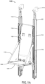
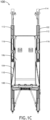
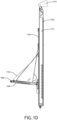
- FIGS. 1A-1D illustrate an aircraft seat assembly 100 in accordance with an embodiment of the present disclosure.
- the seat assembly 100 generally includes a seat frame 102 supporting a seat bucket 104.
- the seat bucket 104 includes a seat back 106 and a seat pan 108 pivotally attached to the seat back 106. Straps 110 may span between the detached edge of the seat pan 108 and the seat back 106, or the seat frame 102, to stabilize and limit rotational motion of the seat pan 108.
- the seat pan 108 may fold upward against the seat back 106 for compact stowage of the seat bucket 104.
- the seat bucket 104 may be equipped with a passenger restraint.
- the seat frame 102 generally includes at least one stanchion 112, and preferably a pair of spaced stanchions 112 in a symmetrical arrangement with the seat bucket 104 centered relative thereto.
- Each stanchion 112 may be elongated and may be coupled to upper and lower frame members including attachments 114 that function to attach the assembly to the aircraft.
- each stanchion 112 is an elongated, thin-walled part formed according to an extrusion process.
- the seat bucket 104 attaches to at least one motion sled 116, and preferably a pair of motion sleds 116 in a symmetrical arrangement.
- the motion sleds 116 are slidably disposed in guide channels formed in the stanchions 112 as discussed further below.
- each stanchion 112 may be stationary and the motion sleds 116 are movable relative to the stanchions 112 during a dynamic event.
- a threshold load value/range may be a lumbar spine load on the occupant as monitored during a dynamic test using an instrumented and anthropomorphically representative test dummy.
- the load value may change depending on the size percentile of the occupant and also can vary between FAA/EASA certified aircraft requirements and non-FAA/EASA qualified aircraft requirements (e.g., military).
- the predetermined motion path is linear and vertical or substantially vertical. In other embodiments, the motion path may include a combination of linear and rotational motions.
- the term "dynamic event" as used herein refers to an event, such as a deceleration or acceleration, of sufficient threshold magnitude to activate the energy absorber system of the seat assembly 100 (e.g., a 12G event, a 16G event, etc.).
- the positions of the motion sleds 116 relative to the stanchions 112 are maintained.
- the energy absorbers act to attenuate energy as the motion sleds 116 stroke relative to the stanchions 112.
- the full range of motion of the motion sleds 116 may range from about 6 inches to about 12 inches depending on the height of the seat bucket 104 relative to the floor.
- the seat bucket 104 attaches to the motion sled 116 at multiple locations, for instance a top attachment location and a bottom attachment location.
- each seat bucket 104 and motion sled 116 coupling includes at least three attachments locations, for instance an upper location, a lower location, and a middle location positioned between the upper and lower locations.
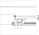
- FIG. 2 illustrates a non-limiting example of an attachment location 118 formed on the motion sled 116 for attaching the seat bucket, directly or indirectly.
- FIG. 2 further illustrates the nested configuration of the motion sled 116 and stanchion 112 as discussed in detail below.
- FIG. 3 illustrates a stanchion assembly including a stanchion 112 and motion sled 116.
- the stanchion defines an elongated guide channel 120 and the motion sled 116 is slidably disposed in the guide channel 120.
- Each of the stanchion 112, motion sled 116 and guide channel 120 are elongated such that the motion sled 116 and stanchion 112 longitudinally overlap a length from about 6 inches to about 36 inches, more preferably from about 12 inches to about 24 inches.
- the comparatively large contact area between the motion sled 116 and stanchion 112 functions to evenly distribute load on the seat bucket from the motion sled 116 to the stanchion 112 forming part of the seat frame.
- the energy absorber and nested configuration of the components work together to facilitate stroking while controlling the seat bucket motion.
- FIG. 4 illustrates the shape and nested configuration of the stanchion 112 and motion sled 116 according to an exemplary embodiment.
- the motion sled 116 is received in the elongated guide channel 120 formed in the stanchion 112.
- the portion of the stanchion 112 forming the guide channel 120 is substantially C-shaped and opens in a first direction
- the motion sled 116 is also substantially C-shaped and opens in a second direction facing the first direction to provide multiple contact surfaces between the motion sled 116 and the stanchion 112.
- a low friction material 122 (i.e., lower coefficient of friction as compared to at least one of the motion sled 116 and the stanchion 112) is positioned at the interface between the motion sled 116 and the stanchion 112 to facilitate smooth stroking of the motion sled 116.
- the low friction material 122 may be a separate layer or coating applied to one of the motion sled 116 and the stanchion 112.
- FIGS. 5 and 6 illustrate non-limiting examples of respective stanchion 112 and motion sled 116 extrusions showing their relatively long lengths.
- FIGS. 7 and 8 illustrates the portion of the seat assembly 100 including the energy absorbers 124.
- Each stanchion assembly includes a motion sled 116 and an energy absorber 124, preferably in a symmetrical arrangement to prevent binding during stroking.
- each energy absorber 124 is a wire bender system including a plurality of rollers 126 affixed to the stanchion 112 and positioned in the elongated guide channel 120.
- a wire 128 is affixed at its lower end to the motion sled 116 and at its upper end my rest in a guide space such that when wire deformation occurs the upper end is kept from straying too fat laterally due to distortion of the wire downstream at the rollers causing movement at the upper end of the wire.
- the wire 128, proximate the bottom attached end is threaded through the rollers 126 such that the wire is bent and unbent as the wire is pulled through the rollers.
- the wire 128 increases in cross section toward a top end of the wire such that resistance to motion increases as the seat bucket strokes further downward relative to the stationary stanchions 116.
- FIG. 9 illustrates a further feature of the aircraft seat assembly, and particularly an internally housed return spring mechanism for automatically returning the deployed seat pan to a stowed position.
- the return spring mechanism is compatible with the motion controller and energy absorbers discussed above or may be employed separately on an aircraft seat without at least one of the motion controller and energy absorbers discussed above.
- the aircraft seat assembly 200 which may also be the assembly 100, generally includes the first and second stanchions 202 (e.g., corresponding to left and right stanchions) positioned parallel and in spaced apart relation.
- Each stanchion 202 forms, defines or otherwise includes an interior space 204 proximate the attachment of the seat pan 206 to the stanchions, such that the first and second stanchions form respective first and second interior spaces.
- Each stanchion defines, forms or otherwise includes a forward slot (see FIG. 10B at 208) providing an entrance and access to the respective interior spaces.
- the forward slots 208 are vertical, narrow, and elongated.
- the seat pan 206 is rotationally coupled, for instance pivotally attached, to the first and second stanchions 202.
- the seat pan 206 is configured to rotate between a stowed position in which the seat pan is folded against the seat back, and a deployed position shown in the figures.
- Seat pan motion is indicated by the directional arrow shown in FIG. 9 .
- the seat pan includes a forward portion 210 defining the sitting surface and first and second rearward extensions 212 or arms that extend through the respective first and second forward slots and are received in the respective first and second interior spaces 204.
- the seat pan 206 includes a tubular U-shaped member 214 supporting a rigid or flexible seat. When the seat pan 206 is deployed as shown, the forward portion 210 extends in the forward direction of the seat and the rearward portions extend in the rearward direction of the seat, toward to the stanchions 202.
- the seat assembly 200 further includes a seat back 216.
- the seat back 216 is attached at one end to the first and second stanchions 202 and at an opposing end to the seat pan 206.
- at least one of the attachments is a pivotal attachment such that movement of the seat pan 206 toward the stowed position causes the bottom end of the seat back 216 to move toward, and in some embodiments between, the first and second stanchions 202.
- First and second spring mechanisms 218 are associated with the respective first and second stanchions 202 and the rearward seat pan extensions and operate to act on the left and right sides of the seat in a symmetrical configuration.
- Each spring mechanism 218 includes an elongated extension spring 220 that resides in its respective interior space 204.
- the first extension spring 220 is therefore attached at one end to the first rearward extension 212 and attached at an opposing end to the first stanchion 202
- the second extension spring 220 is attached at one end to the second rearward extension 212 and attached at an opposing end to the second stanchion 202. Movement of the seat pan 206 toward the deployed position elongates the first and second elongation springs 220 thereby energizing the springs.
- the seat assembly further includes a passenger restraint such as a multi-point restraint 222.
- the seat assembly 200 further includes first and second flexible side bolsters 224 coupled between the seat back 216 and the seat pan 206.
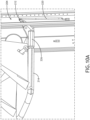
- FIG. 10A illustrates the concealment of the extension springs 220 within the interior spaces 204 formed in the stanchions 202, as well as the attachment of the extension springs 220 between the rearward extensions 212 and respective stanchion 202.
- FIG. 10A further illustrates the tubular U-shaped member 214 received in end fittings 226 forming the rearward extensions 212. Further apparent in FIG. 10A is the attachment location of the seat back forward of the pivotal attachment of the seat pan 206 to the stanchions, thereby providing separate rotational axes for the seat pan and the seat back.
- FIG. 10B illustrates the forward slots 208 and entry of the rearward extensions 212 through the forward slots.
- the forward slots 208 are elongated to accommodate seat pan rotation to energize (e.g., stretch) the elongation springs.
Landscapes
- Engineering & Computer Science (AREA)
- Aviation & Aerospace Engineering (AREA)
- Transportation (AREA)
- Mechanical Engineering (AREA)
- Seats For Vehicles (AREA)
Applications Claiming Priority (1)
| Application Number | Priority Date | Filing Date | Title |
|---|---|---|---|
| US17/966,283 US12240611B2 (en) | 2022-10-14 | 2022-10-14 | Aircraft seat with internal seat pan return spring mechanism |
Publications (2)
| Publication Number | Publication Date |
|---|---|
| EP4353594A1 true EP4353594A1 (de) | 2024-04-17 |
| EP4353594B1 EP4353594B1 (de) | 2025-11-26 |
Family
ID=88315755
Family Applications (1)
| Application Number | Title | Priority Date | Filing Date |
|---|---|---|---|
| EP23202816.7A Active EP4353594B1 (de) | 2022-10-14 | 2023-10-10 | Flugzeugsitz mit innerem sitzschalenrückstellfedermechanismus |
Country Status (2)
| Country | Link |
|---|---|
| US (1) | US12240611B2 (de) |
| EP (1) | EP4353594B1 (de) |
Citations (7)
| Publication number | Priority date | Publication date | Assignee | Title |
|---|---|---|---|---|
| US3594037A (en) * | 1970-04-09 | 1971-07-20 | Mc Donnell Douglas Corp | Cabin attendant seat |
| US4460215A (en) * | 1981-09-30 | 1984-07-17 | The Boeing Company | Folding seat assembly |
| US4740030A (en) * | 1984-07-12 | 1988-04-26 | Nordskog Robert A | Jump seat assembly and seat with improved safety belt array |
| US20180155035A1 (en) * | 2016-12-07 | 2018-06-07 | Rockwell Collins, Inc. | Components for Enhancement of a Low Profile Crew Attendant Seat |
| CN213921513U (zh) * | 2020-10-29 | 2021-08-10 | 北京安达维尔航空设备有限公司 | 一种新型自动收折座椅系统 |
| EP4015386A1 (de) * | 2020-12-21 | 2022-06-22 | B/E Aerospace, Inc. | Flugbegleitersitz mit höhenverstellbarer sitzschale |
| US11465753B2 (en) * | 2020-02-19 | 2022-10-11 | B/E Aerospace, Inc. | Stowable cabin attendant seat with vertically translating backrest |
Family Cites Families (8)
| Publication number | Priority date | Publication date | Assignee | Title |
|---|---|---|---|---|
| GB214099A (en) | 1923-05-09 | 1924-04-17 | Simon Caro Gordon | Improvements in or relating to tip-up seats for cinemas, theatres and the like |
| FR2233798A5 (en) | 1973-06-15 | 1975-01-10 | Caulier Gerard | Theatre seat with tip up action - pivots at rear and operates between stops in arm rests, spring loaded upwards |
| US6152401A (en) * | 1997-12-23 | 2000-11-28 | Air Methods Corporation | Deployable chair system for use in patient transport aircraft |
| US6267426B1 (en) * | 2000-08-29 | 2001-07-31 | Johnson Controls Tech Co | Seat assembly |
| GB2477497B (en) | 2010-02-03 | 2014-04-02 | Mei Chuen Lin | Seat self-lifting device for a portable chair |
| US9848708B2 (en) | 2014-05-08 | 2017-12-26 | Steven T. Windsor | Retractable seat assembly |
| EP3741258B1 (de) | 2019-05-20 | 2025-11-05 | BOCK 1 GmbH & Co. KG | Stuhl mit sitzneigemechanik |
| CN110916412A (zh) | 2019-12-16 | 2020-03-27 | 刘思源 | 一种座面自动保护坐具及其座面自动保护方法 |
-
2022
- 2022-10-14 US US17/966,283 patent/US12240611B2/en active Active
-
2023
- 2023-10-10 EP EP23202816.7A patent/EP4353594B1/de active Active
Patent Citations (7)
| Publication number | Priority date | Publication date | Assignee | Title |
|---|---|---|---|---|
| US3594037A (en) * | 1970-04-09 | 1971-07-20 | Mc Donnell Douglas Corp | Cabin attendant seat |
| US4460215A (en) * | 1981-09-30 | 1984-07-17 | The Boeing Company | Folding seat assembly |
| US4740030A (en) * | 1984-07-12 | 1988-04-26 | Nordskog Robert A | Jump seat assembly and seat with improved safety belt array |
| US20180155035A1 (en) * | 2016-12-07 | 2018-06-07 | Rockwell Collins, Inc. | Components for Enhancement of a Low Profile Crew Attendant Seat |
| US11465753B2 (en) * | 2020-02-19 | 2022-10-11 | B/E Aerospace, Inc. | Stowable cabin attendant seat with vertically translating backrest |
| CN213921513U (zh) * | 2020-10-29 | 2021-08-10 | 北京安达维尔航空设备有限公司 | 一种新型自动收折座椅系统 |
| EP4015386A1 (de) * | 2020-12-21 | 2022-06-22 | B/E Aerospace, Inc. | Flugbegleitersitz mit höhenverstellbarer sitzschale |
Also Published As
| Publication number | Publication date |
|---|---|
| EP4353594B1 (de) | 2025-11-26 |
| US12240611B2 (en) | 2025-03-04 |
| US20240124142A1 (en) | 2024-04-18 |
Similar Documents
| Publication | Publication Date | Title |
|---|---|---|
| US10414503B2 (en) | Components for enhancement of a low profile crew attendant seat | |
| EP3060472B1 (de) | Linear ausfahrbare beinauflage eines flugzeugsitzes | |
| EP3868664B1 (de) | Verstaubarer flugbegleitersitz mit vertikal verschiebbarer rückenlehne | |
| EP3929088B1 (de) | Flugbegleitersitz eines flugzeugs mit einer zusätzlichen verstellbaren platte | |
| EP3393906B1 (de) | Passagiersitz mit verschiebbarem sitzelement | |
| EP3126240B1 (de) | Entfaltbare integrierte beinstütze für neigbare passagiersitze | |
| US20150307194A1 (en) | Aircraft seat with occupant weight sensing mechanism to adjust tilt-recline force | |
| EP3626619A1 (de) | Mehrstufiges sitzlehnenverlängerungssystem | |
| EP3225552B1 (de) | Profilierter umklappbarer sitz | |
| EP4335745B1 (de) | Flugzeugsitz mit energiedämpfender messplatte | |
| CN110893809B (zh) | 用于头枕的延伸辅助装置 | |
| US7226131B2 (en) | Adjustable seat belt guide assembly | |
| EP4353594B1 (de) | Flugzeugsitz mit innerem sitzschalenrückstellfedermechanismus | |
| EP4353589B1 (de) | Versetzter hubschrauberpilotsitz mit zentriertem vertikalbewegungssystem | |
| US12252253B2 (en) | Aircraft seat with nested energy attenuation guide system | |
| US12447871B2 (en) | Passenger seat with forward adjustable backrest | |
| EP4015386B1 (de) | Flugbegleitersitz mit höhenverstellbarer sitzschale | |
| US11548643B2 (en) | Cabin attendant seat with height adjustable seat pan | |
| US12195187B2 (en) | Offset helicopter pilot seat with singular energy absorber | |
| EP4282760B1 (de) | Fahrgastsitz mit nach vorne verstellbarer rückenlehne | |
| US10399468B2 (en) | Occupant restraint actuated apparatus for dynamically stiffening a motor vehicle seat back | |
| JP7327348B2 (ja) | 車両用シートベルト装置 | |
| EP4353526A2 (de) | Vorrichtung zur einschränkung der aktuatorbewegung während eines dynamischen ereignisses | |
| US12403804B2 (en) | Armrest control mechanism for passenger seat |
Legal Events
| Date | Code | Title | Description |
|---|---|---|---|
| PUAI | Public reference made under article 153(3) epc to a published international application that has entered the european phase |
Free format text: ORIGINAL CODE: 0009012 |
|
| STAA | Information on the status of an ep patent application or granted ep patent |
Free format text: STATUS: THE APPLICATION HAS BEEN PUBLISHED |
|
| STAA | Information on the status of an ep patent application or granted ep patent |
Free format text: STATUS: REQUEST FOR EXAMINATION WAS MADE |
|
| AK | Designated contracting states |
Kind code of ref document: A1 Designated state(s): AL AT BE BG CH CY CZ DE DK EE ES FI FR GB GR HR HU IE IS IT LI LT LU LV MC ME MK MT NL NO PL PT RO RS SE SI SK SM TR |
|
| 17P | Request for examination filed |
Effective date: 20240410 |
|
| RBV | Designated contracting states (corrected) |
Designated state(s): AL AT BE BG CH CY CZ DE DK EE ES FI FR GB GR HR HU IE IS IT LI LT LU LV MC ME MK MT NL NO PL PT RO RS SE SI SK SM TR |
|
| STAA | Information on the status of an ep patent application or granted ep patent |
Free format text: STATUS: EXAMINATION IS IN PROGRESS |
|
| 17Q | First examination report despatched |
Effective date: 20250124 |
|
| GRAP | Despatch of communication of intention to grant a patent |
Free format text: ORIGINAL CODE: EPIDOSNIGR1 |
|
| STAA | Information on the status of an ep patent application or granted ep patent |
Free format text: STATUS: GRANT OF PATENT IS INTENDED |
|
| INTG | Intention to grant announced |
Effective date: 20250519 |
|
| GRAS | Grant fee paid |
Free format text: ORIGINAL CODE: EPIDOSNIGR3 |
|
| GRAA | (expected) grant |
Free format text: ORIGINAL CODE: 0009210 |
|
| STAA | Information on the status of an ep patent application or granted ep patent |
Free format text: STATUS: THE PATENT HAS BEEN GRANTED |
|
| AK | Designated contracting states |
Kind code of ref document: B1 Designated state(s): AL AT BE BG CH CY CZ DE DK EE ES FI FR GB GR HR HU IE IS IT LI LT LU LV MC ME MK MT NL NO PL PT RO RS SE SI SK SM TR |
|
| REG | Reference to a national code |
Ref country code: CH Ref legal event code: F10 Free format text: ST27 STATUS EVENT CODE: U-0-0-F10-F00 (AS PROVIDED BY THE NATIONAL OFFICE) Effective date: 20251126 Ref country code: GB Ref legal event code: FG4D |
|
| REG | Reference to a national code |
Ref country code: IE Ref legal event code: FG4D |
|
| REG | Reference to a national code |
Ref country code: DE Ref legal event code: R096 Ref document number: 602023008965 Country of ref document: DE |
|
| REG | Reference to a national code |
Ref country code: NL Ref legal event code: MP Effective date: 20251126 |
|
| PG25 | Lapsed in a contracting state [announced via postgrant information from national office to epo] |
Ref country code: ES Free format text: LAPSE BECAUSE OF FAILURE TO SUBMIT A TRANSLATION OF THE DESCRIPTION OR TO PAY THE FEE WITHIN THE PRESCRIBED TIME-LIMIT Effective date: 20251126 |
|
| REG | Reference to a national code |
Ref country code: LT Ref legal event code: MG9D |
|
| PG25 | Lapsed in a contracting state [announced via postgrant information from national office to epo] |
Ref country code: NO Free format text: LAPSE BECAUSE OF FAILURE TO SUBMIT A TRANSLATION OF THE DESCRIPTION OR TO PAY THE FEE WITHIN THE PRESCRIBED TIME-LIMIT Effective date: 20260226 |
|
| PG25 | Lapsed in a contracting state [announced via postgrant information from national office to epo] |
Ref country code: FI Free format text: LAPSE BECAUSE OF FAILURE TO SUBMIT A TRANSLATION OF THE DESCRIPTION OR TO PAY THE FEE WITHIN THE PRESCRIBED TIME-LIMIT Effective date: 20251126 Ref country code: HR Free format text: LAPSE BECAUSE OF FAILURE TO SUBMIT A TRANSLATION OF THE DESCRIPTION OR TO PAY THE FEE WITHIN THE PRESCRIBED TIME-LIMIT Effective date: 20251126 Ref country code: AT Free format text: LAPSE BECAUSE OF FAILURE TO SUBMIT A TRANSLATION OF THE DESCRIPTION OR TO PAY THE FEE WITHIN THE PRESCRIBED TIME-LIMIT Effective date: 20251126 |
|
| REG | Reference to a national code |
Ref country code: AT Ref legal event code: MK05 Ref document number: 1860863 Country of ref document: AT Kind code of ref document: T Effective date: 20251126 |
|
| PG25 | Lapsed in a contracting state [announced via postgrant information from national office to epo] |
Ref country code: NL Free format text: LAPSE BECAUSE OF FAILURE TO SUBMIT A TRANSLATION OF THE DESCRIPTION OR TO PAY THE FEE WITHIN THE PRESCRIBED TIME-LIMIT Effective date: 20251126 |
|
| PG25 | Lapsed in a contracting state [announced via postgrant information from national office to epo] |
Ref country code: RS Free format text: LAPSE BECAUSE OF FAILURE TO SUBMIT A TRANSLATION OF THE DESCRIPTION OR TO PAY THE FEE WITHIN THE PRESCRIBED TIME-LIMIT Effective date: 20260226 |
|
| PG25 | Lapsed in a contracting state [announced via postgrant information from national office to epo] |
Ref country code: IS Free format text: LAPSE BECAUSE OF FAILURE TO SUBMIT A TRANSLATION OF THE DESCRIPTION OR TO PAY THE FEE WITHIN THE PRESCRIBED TIME-LIMIT Effective date: 20260326 |
|
| PG25 | Lapsed in a contracting state [announced via postgrant information from national office to epo] |
Ref country code: PT Free format text: LAPSE BECAUSE OF FAILURE TO SUBMIT A TRANSLATION OF THE DESCRIPTION OR TO PAY THE FEE WITHIN THE PRESCRIBED TIME-LIMIT Effective date: 20260326 |
|
| PG25 | Lapsed in a contracting state [announced via postgrant information from national office to epo] |
Ref country code: PL Free format text: LAPSE BECAUSE OF FAILURE TO SUBMIT A TRANSLATION OF THE DESCRIPTION OR TO PAY THE FEE WITHIN THE PRESCRIBED TIME-LIMIT Effective date: 20251126 |
|
| PG25 | Lapsed in a contracting state [announced via postgrant information from national office to epo] |
Ref country code: LV Free format text: LAPSE BECAUSE OF FAILURE TO SUBMIT A TRANSLATION OF THE DESCRIPTION OR TO PAY THE FEE WITHIN THE PRESCRIBED TIME-LIMIT Effective date: 20251126 |