EP4353618B1 - Entlüftungsvorrichtung und verfahren zur herstellung davon - Google Patents
Entlüftungsvorrichtung und verfahren zur herstellung davon Download PDFInfo
- Publication number
- EP4353618B1 EP4353618B1 EP24159325.0A EP24159325A EP4353618B1 EP 4353618 B1 EP4353618 B1 EP 4353618B1 EP 24159325 A EP24159325 A EP 24159325A EP 4353618 B1 EP4353618 B1 EP 4353618B1
- Authority
- EP
- European Patent Office
- Prior art keywords
- sheet
- venting device
- plate spring
- ball
- passage
- Prior art date
- Legal status (The legal status is an assumption and is not a legal conclusion. Google has not performed a legal analysis and makes no representation as to the accuracy of the status listed.)
- Active
Links
Images







Classifications
-
- B—PERFORMING OPERATIONS; TRANSPORTING
- B65—CONVEYING; PACKING; STORING; HANDLING THIN OR FILAMENTARY MATERIAL
- B65D—CONTAINERS FOR STORAGE OR TRANSPORT OF ARTICLES OR MATERIALS, e.g. BAGS, BARRELS, BOTTLES, BOXES, CANS, CARTONS, CRATES, DRUMS, JARS, TANKS, HOPPERS, FORWARDING CONTAINERS; ACCESSORIES, CLOSURES, OR FITTINGS THEREFOR; PACKAGING ELEMENTS; PACKAGES
- B65D51/00—Closures not otherwise provided for
- B65D51/16—Closures not otherwise provided for with means for venting air or gas
- B65D51/1633—Closures not otherwise provided for with means for venting air or gas whereby venting occurs by automatic opening of the closure, container or other element
- B65D51/1644—Closures not otherwise provided for with means for venting air or gas whereby venting occurs by automatic opening of the closure, container or other element the element being a valve
-
- B—PERFORMING OPERATIONS; TRANSPORTING
- B65—CONVEYING; PACKING; STORING; HANDLING THIN OR FILAMENTARY MATERIAL
- B65D—CONTAINERS FOR STORAGE OR TRANSPORT OF ARTICLES OR MATERIALS, e.g. BAGS, BARRELS, BOTTLES, BOXES, CANS, CARTONS, CRATES, DRUMS, JARS, TANKS, HOPPERS, FORWARDING CONTAINERS; ACCESSORIES, CLOSURES, OR FITTINGS THEREFOR; PACKAGING ELEMENTS; PACKAGES
- B65D75/00—Packages comprising articles or materials partially or wholly enclosed in strips, sheets, blanks, tubes or webs of flexible sheet material, e.g. in folded wrappers
- B65D75/04—Articles or materials wholly enclosed in single sheets or wrapper blanks
- B65D75/20—Articles or materials wholly enclosed in single sheets or wrapper blanks in sheets or blanks doubled around contents and having their opposed free margins united, e.g. by pressure-sensitive adhesive, crimping, heat-sealing, or welding
- B65D75/22—Articles or materials wholly enclosed in single sheets or wrapper blanks in sheets or blanks doubled around contents and having their opposed free margins united, e.g. by pressure-sensitive adhesive, crimping, heat-sealing, or welding the sheet or blank being recessed to accommodate contents
-
- F—MECHANICAL ENGINEERING; LIGHTING; HEATING; WEAPONS; BLASTING
- F16—ENGINEERING ELEMENTS AND UNITS; GENERAL MEASURES FOR PRODUCING AND MAINTAINING EFFECTIVE FUNCTIONING OF MACHINES OR INSTALLATIONS; THERMAL INSULATION IN GENERAL
- F16K—VALVES; TAPS; COCKS; ACTUATING-FLOATS; DEVICES FOR VENTING OR AERATING
- F16K17/00—Safety valves; Equalising valves, e.g. pressure relief valves
- F16K17/02—Safety valves; Equalising valves, e.g. pressure relief valves opening on surplus pressure on one side; closing on insufficient pressure on one side
- F16K17/04—Safety valves; Equalising valves, e.g. pressure relief valves opening on surplus pressure on one side; closing on insufficient pressure on one side spring-loaded
-
- F—MECHANICAL ENGINEERING; LIGHTING; HEATING; WEAPONS; BLASTING
- F16—ENGINEERING ELEMENTS AND UNITS; GENERAL MEASURES FOR PRODUCING AND MAINTAINING EFFECTIVE FUNCTIONING OF MACHINES OR INSTALLATIONS; THERMAL INSULATION IN GENERAL
- F16K—VALVES; TAPS; COCKS; ACTUATING-FLOATS; DEVICES FOR VENTING OR AERATING
- F16K17/00—Safety valves; Equalising valves, e.g. pressure relief valves
- F16K17/02—Safety valves; Equalising valves, e.g. pressure relief valves opening on surplus pressure on one side; closing on insufficient pressure on one side
- F16K17/04—Safety valves; Equalising valves, e.g. pressure relief valves opening on surplus pressure on one side; closing on insufficient pressure on one side spring-loaded
- F16K17/0406—Safety valves; Equalising valves, e.g. pressure relief valves opening on surplus pressure on one side; closing on insufficient pressure on one side spring-loaded in the form of balls
-
- F—MECHANICAL ENGINEERING; LIGHTING; HEATING; WEAPONS; BLASTING
- F16—ENGINEERING ELEMENTS AND UNITS; GENERAL MEASURES FOR PRODUCING AND MAINTAINING EFFECTIVE FUNCTIONING OF MACHINES OR INSTALLATIONS; THERMAL INSULATION IN GENERAL
- F16K—VALVES; TAPS; COCKS; ACTUATING-FLOATS; DEVICES FOR VENTING OR AERATING
- F16K17/00—Safety valves; Equalising valves, e.g. pressure relief valves
- F16K17/02—Safety valves; Equalising valves, e.g. pressure relief valves opening on surplus pressure on one side; closing on insufficient pressure on one side
- F16K17/04—Safety valves; Equalising valves, e.g. pressure relief valves opening on surplus pressure on one side; closing on insufficient pressure on one side spring-loaded
- F16K17/0466—Safety valves; Equalising valves, e.g. pressure relief valves opening on surplus pressure on one side; closing on insufficient pressure on one side spring-loaded with a special seating surface
-
- F—MECHANICAL ENGINEERING; LIGHTING; HEATING; WEAPONS; BLASTING
- F16—ENGINEERING ELEMENTS AND UNITS; GENERAL MEASURES FOR PRODUCING AND MAINTAINING EFFECTIVE FUNCTIONING OF MACHINES OR INSTALLATIONS; THERMAL INSULATION IN GENERAL
- F16K—VALVES; TAPS; COCKS; ACTUATING-FLOATS; DEVICES FOR VENTING OR AERATING
- F16K17/00—Safety valves; Equalising valves, e.g. pressure relief valves
- F16K17/02—Safety valves; Equalising valves, e.g. pressure relief valves opening on surplus pressure on one side; closing on insufficient pressure on one side
- F16K17/04—Safety valves; Equalising valves, e.g. pressure relief valves opening on surplus pressure on one side; closing on insufficient pressure on one side spring-loaded
- F16K17/0493—Safety valves; Equalising valves, e.g. pressure relief valves opening on surplus pressure on one side; closing on insufficient pressure on one side spring-loaded with a spring other than a helicoidal spring
-
- H—ELECTRICITY
- H01—ELECTRIC ELEMENTS
- H01M—PROCESSES OR MEANS, e.g. BATTERIES, FOR THE DIRECT CONVERSION OF CHEMICAL ENERGY INTO ELECTRICAL ENERGY
- H01M10/00—Secondary cells; Manufacture thereof
- H01M10/05—Accumulators with non-aqueous electrolyte
- H01M10/052—Li-accumulators
-
- H—ELECTRICITY
- H01—ELECTRIC ELEMENTS
- H01M—PROCESSES OR MEANS, e.g. BATTERIES, FOR THE DIRECT CONVERSION OF CHEMICAL ENERGY INTO ELECTRICAL ENERGY
- H01M50/00—Constructional details or processes of manufacture of the non-active parts of electrochemical cells other than fuel cells, e.g. hybrid cells
- H01M50/10—Primary casings; Jackets or wrappings
- H01M50/102—Primary casings; Jackets or wrappings characterised by their shape or physical structure
- H01M50/105—Pouches or flexible bags
-
- H—ELECTRICITY
- H01—ELECTRIC ELEMENTS
- H01M—PROCESSES OR MEANS, e.g. BATTERIES, FOR THE DIRECT CONVERSION OF CHEMICAL ENERGY INTO ELECTRICAL ENERGY
- H01M50/00—Constructional details or processes of manufacture of the non-active parts of electrochemical cells other than fuel cells, e.g. hybrid cells
- H01M50/10—Primary casings; Jackets or wrappings
- H01M50/116—Primary casings; Jackets or wrappings characterised by the material
- H01M50/117—Inorganic material
- H01M50/119—Metals
-
- H—ELECTRICITY
- H01—ELECTRIC ELEMENTS
- H01M—PROCESSES OR MEANS, e.g. BATTERIES, FOR THE DIRECT CONVERSION OF CHEMICAL ENERGY INTO ELECTRICAL ENERGY
- H01M50/00—Constructional details or processes of manufacture of the non-active parts of electrochemical cells other than fuel cells, e.g. hybrid cells
- H01M50/10—Primary casings; Jackets or wrappings
- H01M50/116—Primary casings; Jackets or wrappings characterised by the material
- H01M50/121—Organic material
-
- H—ELECTRICITY
- H01—ELECTRIC ELEMENTS
- H01M—PROCESSES OR MEANS, e.g. BATTERIES, FOR THE DIRECT CONVERSION OF CHEMICAL ENERGY INTO ELECTRICAL ENERGY
- H01M50/00—Constructional details or processes of manufacture of the non-active parts of electrochemical cells other than fuel cells, e.g. hybrid cells
- H01M50/10—Primary casings; Jackets or wrappings
- H01M50/116—Primary casings; Jackets or wrappings characterised by the material
- H01M50/122—Composite material consisting of a mixture of organic and inorganic materials
-
- H—ELECTRICITY
- H01—ELECTRIC ELEMENTS
- H01M—PROCESSES OR MEANS, e.g. BATTERIES, FOR THE DIRECT CONVERSION OF CHEMICAL ENERGY INTO ELECTRICAL ENERGY
- H01M50/00—Constructional details or processes of manufacture of the non-active parts of electrochemical cells other than fuel cells, e.g. hybrid cells
- H01M50/10—Primary casings; Jackets or wrappings
- H01M50/116—Primary casings; Jackets or wrappings characterised by the material
- H01M50/124—Primary casings; Jackets or wrappings characterised by the material having a layered structure
- H01M50/126—Primary casings; Jackets or wrappings characterised by the material having a layered structure comprising three or more layers
-
- H—ELECTRICITY
- H01—ELECTRIC ELEMENTS
- H01M—PROCESSES OR MEANS, e.g. BATTERIES, FOR THE DIRECT CONVERSION OF CHEMICAL ENERGY INTO ELECTRICAL ENERGY
- H01M50/00—Constructional details or processes of manufacture of the non-active parts of electrochemical cells other than fuel cells, e.g. hybrid cells
- H01M50/30—Arrangements for facilitating escape of gases
-
- H—ELECTRICITY
- H01—ELECTRIC ELEMENTS
- H01M—PROCESSES OR MEANS, e.g. BATTERIES, FOR THE DIRECT CONVERSION OF CHEMICAL ENERGY INTO ELECTRICAL ENERGY
- H01M50/00—Constructional details or processes of manufacture of the non-active parts of electrochemical cells other than fuel cells, e.g. hybrid cells
- H01M50/30—Arrangements for facilitating escape of gases
- H01M50/317—Re-sealable arrangements
-
- H—ELECTRICITY
- H01—ELECTRIC ELEMENTS
- H01M—PROCESSES OR MEANS, e.g. BATTERIES, FOR THE DIRECT CONVERSION OF CHEMICAL ENERGY INTO ELECTRICAL ENERGY
- H01M50/00—Constructional details or processes of manufacture of the non-active parts of electrochemical cells other than fuel cells, e.g. hybrid cells
- H01M50/30—Arrangements for facilitating escape of gases
- H01M50/317—Re-sealable arrangements
- H01M50/325—Re-sealable arrangements comprising deformable valve members, e.g. elastic or flexible valve members
-
- H—ELECTRICITY
- H01—ELECTRIC ELEMENTS
- H01M—PROCESSES OR MEANS, e.g. BATTERIES, FOR THE DIRECT CONVERSION OF CHEMICAL ENERGY INTO ELECTRICAL ENERGY
- H01M50/00—Constructional details or processes of manufacture of the non-active parts of electrochemical cells other than fuel cells, e.g. hybrid cells
- H01M50/30—Arrangements for facilitating escape of gases
- H01M50/317—Re-sealable arrangements
- H01M50/325—Re-sealable arrangements comprising deformable valve members, e.g. elastic or flexible valve members
- H01M50/333—Spring-loaded vent valves
-
- H—ELECTRICITY
- H01—ELECTRIC ELEMENTS
- H01M—PROCESSES OR MEANS, e.g. BATTERIES, FOR THE DIRECT CONVERSION OF CHEMICAL ENERGY INTO ELECTRICAL ENERGY
- H01M50/00—Constructional details or processes of manufacture of the non-active parts of electrochemical cells other than fuel cells, e.g. hybrid cells
- H01M50/30—Arrangements for facilitating escape of gases
- H01M50/35—Gas exhaust passages comprising elongated, tortuous or labyrinth-shaped exhaust passages
-
- H—ELECTRICITY
- H01—ELECTRIC ELEMENTS
- H01M—PROCESSES OR MEANS, e.g. BATTERIES, FOR THE DIRECT CONVERSION OF CHEMICAL ENERGY INTO ELECTRICAL ENERGY
- H01M2200/00—Safety devices for primary or secondary batteries
- H01M2200/20—Pressure-sensitive devices
-
- H—ELECTRICITY
- H01—ELECTRIC ELEMENTS
- H01M—PROCESSES OR MEANS, e.g. BATTERIES, FOR THE DIRECT CONVERSION OF CHEMICAL ENERGY INTO ELECTRICAL ENERGY
- H01M50/00—Constructional details or processes of manufacture of the non-active parts of electrochemical cells other than fuel cells, e.g. hybrid cells
- H01M50/50—Current conducting connections for cells or batteries
- H01M50/543—Terminals
- H01M50/547—Terminals characterised by the disposition of the terminals on the cells
- H01M50/55—Terminals characterised by the disposition of the terminals on the cells on the same side of the cell
-
- H—ELECTRICITY
- H01—ELECTRIC ELEMENTS
- H01M—PROCESSES OR MEANS, e.g. BATTERIES, FOR THE DIRECT CONVERSION OF CHEMICAL ENERGY INTO ELECTRICAL ENERGY
- H01M50/00—Constructional details or processes of manufacture of the non-active parts of electrochemical cells other than fuel cells, e.g. hybrid cells
- H01M50/50—Current conducting connections for cells or batteries
- H01M50/543—Terminals
- H01M50/552—Terminals characterised by their shape
- H01M50/553—Terminals adapted for prismatic, pouch or rectangular cells
- H01M50/557—Plate-shaped terminals
-
- H—ELECTRICITY
- H01—ELECTRIC ELEMENTS
- H01M—PROCESSES OR MEANS, e.g. BATTERIES, FOR THE DIRECT CONVERSION OF CHEMICAL ENERGY INTO ELECTRICAL ENERGY
- H01M50/00—Constructional details or processes of manufacture of the non-active parts of electrochemical cells other than fuel cells, e.g. hybrid cells
- H01M50/50—Current conducting connections for cells or batteries
- H01M50/543—Terminals
- H01M50/562—Terminals characterised by the material
-
- Y—GENERAL TAGGING OF NEW TECHNOLOGICAL DEVELOPMENTS; GENERAL TAGGING OF CROSS-SECTIONAL TECHNOLOGIES SPANNING OVER SEVERAL SECTIONS OF THE IPC; TECHNICAL SUBJECTS COVERED BY FORMER USPC CROSS-REFERENCE ART COLLECTIONS [XRACs] AND DIGESTS
- Y02—TECHNOLOGIES OR APPLICATIONS FOR MITIGATION OR ADAPTATION AGAINST CLIMATE CHANGE
- Y02E—REDUCTION OF GREENHOUSE GAS [GHG] EMISSIONS, RELATED TO ENERGY GENERATION, TRANSMISSION OR DISTRIBUTION
- Y02E60/00—Enabling technologies; Technologies with a potential or indirect contribution to GHG emissions mitigation
- Y02E60/10—Energy storage using batteries
Definitions
- the present invention relates to a venting device and a method for manufacturing the same, and more particularly, to at least one venting device, which is inserted into a sealing part of a pouch of a secondary battery to discharge an internal gas when an internal pressure of the pouch increases so as to adjust the internal pressure, and a method for manufacturing the same.
- secondary batteries include nickel-cadmium batteries, nickel-hydrogen batteries, lithium ion batteries, and lithium ion polymer batteries.
- Such a secondary battery is being applied to and used in small-sized products such as digital cameras, P-DVDs, MP3Ps, mobile phones, PDAs, portable game devices, power tools, E-bikes, and the like as well as large-sized products requiring high power such as electric vehicles and hybrid vehicles, power storage devices for storing surplus power or renewable energy, and backup power storage devices.
- Such a secondary battery is classified into a pouch type secondary battery and a can type secondary battery according to a material of a case accommodating the electrode assembly.
- a pouch type secondary battery an electrode assembly is accommodated in a pouch made of a flexible polymer material.
- an electrode assembly is accommodated in a case made of a metal or plastic material.
- a gas may be generated by internal short-circuit, overcharging, overdischarging, or the like due to an external impact.
- an electrochemical reaction between an electrolyte and an electrode active material is quickly accelerated by the high temperature to generate a gas.
- the generated gas may allow the secondary battery to increase in internal pressure to cause problems such as weakening of bonding force between components, damage of a case of the secondary battery, an early operation of a protection circuit, deformation of an electrode, internal short-circuit, explosion, and the like.
- a protection member such as a CID filter and a safety vent is provided.
- electrical connection may be physically interrupted.
- the protection member is not sufficiently provided.
- An object to be solved by the present invention is to provide at least one venting device, which is inserted into a sealing part of a pouch of a secondary battery to discharge an internal gas when an internal pressure of the pouch increases so as to adjust the internal pressure, and a method for manufacturing the same.
- an end of the other side of the plate spring may be bent toward the sheet inserted into the insertion space.
- the polymer includes an acid-treated polyolefin-based polymer.
- the metal may include aluminum or stainless steel.
- the surface treatment layer may include at least one of chromium, zirconium, and titanium.
- the lower housing may have a width less than that of the upper housing.
- the upper housing may have a circular cylinder shape
- the lower housing may have an oval cylinder shape
- the step of forming the surface treatment layer may include: a step of debinding the metal plate; a primarily washing step; an etching step; a secondarily washing step; a surface treatment step; a tertiarily washing step; and a drying step.
- the surface treatment step may include a step of performing one of chromate treatment, zirconia treatment, and titanium treatment.
- the method may further include: a step of allowing a plate spring having a cap shape to surround the sheet and the ball; and a step of inserting the sheet into a housing inserted between both surfaces of the sealing part so as to be sealed together with the sealing part.
- the embodiments of the present invention may have at least the following effects.
- the adhesion between the ball and the sheet may be improved to improve the sealability when the passage is closed.
- FIG. 1 is an assembled view of a secondary battery 1 including a venting device 15 according to an embodiment of the present invention
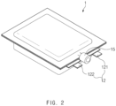
- FIG. 2 is a perspective view of the secondary battery 1 of FIG. 1 , which is completely manufactured.
- the electrode assembly 10 includes an electrode tab 11.
- the electrode tab 11 is connected to each of a positive electrode and a negative electrode of the electrode assembly 10 to protrude to the outside of the electrode assembly 10, thereby providing a path, through which electrons are moved, between the inside and outside of the electrode assembly 10.
- the electrode collector of the electrode assembly 10 is constituted by a portion coated with the slurry and a distal end, on which the slurry is not applied, i.e., a non-coating portion.
- the electrode tab 11 may be formed by cutting the non-coating portion or by connecting a separate conductive member to the non-coating portion through ultrasonic welding.
- the electrode tabs 11 may protrude from one side of the electrode assembly 10 in the same direction, but the present invention is not limited thereto.
- the electrode tabs 11 may protrude in directions different from each other.
- the electrode lead 12 is connected to the electrode tab 11 through spot welding. Also, a portion of the electrode lead 12 is surrounded by an insulation part 14.
- the insulation part 14 may be disposed to be limited within a sealing part 134, at which an upper pouch 131 and a lower pouch 132 of the battery case 13 are thermally fused, so that the electrode lead 12 is bonded to the battery case 13. Also, electricity generated from the electrode assembly 10 may be prevented from flowing to the battery case 13 through the electrode lead 12, and the sealing of the battery case 13 may be maintained.
- the insulation part 14 may be made of a nonconductor having non-conductivity, which is not electrically conductive.
- the present invention is not limited thereto.
- various members may be used as the insulation part 14 as long as the members are capable of insulating the electrode lead 12.
- the battery case 13 may be a pouch made of a flexible material.
- the battery case 13 accommodates the electrode assembly 10 so that a portion of the electrode lead 12, i.e., the terminal part is exposed and then is sealed.
- the battery case 13 includes the upper pouch 131 and the lower pouch 132.
- a cup part 133 having an accommodation space 1331 accommodating the electrode assembly 10 is formed in the lower pouch 132, and the upper pouch 131 covers an upper portion of the accommodation space 1331 to prevent the electrode assembly 10 from being separated to the outside of the battery case 13.
- the cup part 133 having the accommodation space 1331 may be formed in the upper pouch 131 to accommodate the electrode assembly 10 in the upper portion.
- one side of the upper pouch 131 and one side of the lower pouch 132 may be connected to each other.
- the present invention is not limited thereto.
- the upper pouch 131 and the lower pouch may be separately manufactured to be separated from each other.
- the electrode assembly 10 When the electrode lead 12 is connected to the electrode tab 11 of the electrode assembly 10, and the insulation part 14 is provided on a portion of the electrode lead 12, the electrode assembly 10 may be accommodated in the accommodation space 1331 provided in the lower pouch 132, and the upper pouch 131 may cover the upper side of the accommodation space 1331. Also, when the electrolyte is injected, and the sealing part 134 provided on the edge of each of the upper pouch 131 and the lower pouch 132 is sealed, the secondary battery 1 is manufactured as illustrated in FIG. 2 .
- the gas barrier layer 1351 may be made of one material or a mixture of two or more materials selected from the group consisting of Fe, C, Cr, Mn, Ni and Al.
- the gas barrier layer 1351 is made of a material containing iron, the mechanical strength may be improved.
- the gas barrier layer 1351 is made of a material containing aluminum, flexibility may be improved.
- the material forming the gas barrier layer 1351 may be used in consideration of the characteristics of the gas barrier layer 1351.
- the surface protection layer 1352 is made of a polymer and disposed at the outermost layer to protect the secondary battery 1 against external friction and collision and also electrically insulates the electrode assembly 10 from the outside.
- the outermost layer represents a direction opposite to a direction in which the electrode assembly 10 is disposed with respect to the gas barrier layer 1351, i.e., in an outward direction.
- the surface protection layer 1352 may be made of at least one or more materials selected from the group consisting of polyethylene, polypropylene, polycarbonate, polyethylene terephthalate, polyvinyl chloride, acrylic polymer, polyacrylonitrile, polyimide, polyamide, cellulose, aramid, nylon, polyester, polyparaphenylene benzobisoxazole, polyarylate, teflon, and glass fiber. Particularly, a polymer such as a nylon resin or polyethylene terephthalate (PET) having mainly abrasion resistance and heat resistance is used. Also, the surface protection layer 1352 may have a single layer structure made of one material or a composite layer structure in which two or more materials are respectively formed as layers.
- the sealant layer 1353 is made of a polymer and disposed at the innermost layer to directly contact the electrode assembly 10.
- the pouch type battery case 13 may be manufactured while a portion thereof is stretched to form the cup part 133 having the accommodation space 1331 having a bag shape when the pouch film 135 having the lamination structure as described above is drawn by using a punch or the like. Also, when the electrode assembly 10 is accommodated in the accommodation space 1331, the electrolyte is injected. Thereafter, when the upper pouch 131 and the lower pouch 132 may contact each other, and thermal compression is applied to the sealing part 134, the sealant layers 1353 may be bonded to each other to seal the battery case 13.
- the sealant layer 1353 since the sealant layer 1353 directly contacts the electrode assembly 10, the sealant layer 1353 may have to have insulating properties. Also, since the sealant layer 1353 contacts the electrolyte, the sealant layer 1353 may have to have corrosion resistance. Also, since the inside of the battery case 13 is completely sealed to prevent materials from moving between the inside and outside of the battery case 13, high sealability has to be realized. That is, the sealing part 134 in which the sealant layers 1353 are bonded to each other should have superior bonding strength.
- the sealant layer 1353 may be made of at least one or more materials selected from the group consisting of polyethylene, polypropylene, polycarbonate, polyethylene terephthalate, polyvinyl chloride, acrylic polymer, polyacrylonitrile, polyimide, polyamide, cellulose, aramid, nylon, polyester, polyparaphenylene benzobisoxazole, polyarylate, teflon, and glass fiber.
- a polyolefin-based resin such as polypropylene (PP) or polyethylene (PE) may be used for the sealant layer 1353.
- Polypropylene (PP) is excellent in mechanical properties such as tensile strength, rigidity, surface hardness, abrasion resistance, and heat resistance and chemical properties such as corrosion resistance and thus is mainly used for manufacturing the sealant layer 1353.
- the sealant layer 1353 may be made of a cated polypropylene or a polypropylene-butylene-ethylene terpolymer.
- the sealant layer 1353 may have a single layer structure made of one material or a composite layer structure in which two or more materials are respectively formed as layers.
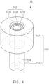
- the secondary battery 1 further includes at least one venting device 15. At least one venting device 15 is inserted into the sealing part 134 of the pouch of the secondary battery 1 to discharge the internal gas when the internal pressure of the pouch increase, thereby adjusting the pressure.
- the upper housing 1511 may have a transverse cross-section having a circular cylinder shape
- the lower housing 1512 may have a transverse cross-section having an oval cylinder shape.
- the lower housing 1512 may have a width less than that of the upper housing 1511.
- the lower housing 1512 may be inserted between both the surfaces of the sealing part 134 so as to be sealed together with the sealing part 134.
- the lower housing 1512 may be fused to the inner surface of the sealing part 134, and the upper housing 1511 may protrude to the outside of the pouch.
- the sealing part 134 has to be deformed in size.
- the sealing of the sealing part 134 may be damaged.
- the lower housing 1512 may have a width less than a thickness of the sealing part 134. Particularly, it is preferable that a long axis of the transverse cross-section has a width that is 6 mm or more less. Also, if the upper housing 1511 has an excessively large size, the upper housing 1511 protruding to the outside of the pouch may interfere with other secondary batteries 1 that are disposed in the vicinity of the upper housing 1511. Thus, it may be difficult to assemble a package or module of the secondary battery 1. Thus, the upper housing 1511 may have a width less than a thickness of the sealing part 134. Particularly, it is preferable that the transverse cross-section has a diameter 8 mm or more less. However, the present invention is not limited thereto. For example, the upper housing 1511 and the lower housing 1512 may have various shapes, for example, one cylinder shape without being distinguished from each other.
- the sheet 152 may be formed in the housing 151 and made of a metal. Also, the passage 154 through which the inside and the outside of the pouch communicate with each other may be formed to pass through a center of the sheet 152. The sheet 152 will be described below in detail.
- the plate spring 153 may be made of a metal to open and close the passage 154 formed in the sheet 152 according to an internal pressure of the pouch. Particularly, when the internal pressure of the pouch is less than a specific pressure, the plate spring 153 may contact the sheet 152 to close the outlet 1541 of the passage 154. Also, when the internal pressure of the pouch gradually increase to exceed the specific pressure, the plate spring 153 may be spaced apart from the sheet 152 to open the outlet 1541 of the passage 154.
- the passage 154 is closed by using a coil spring.
- the venting device has to be miniaturized so as to be inserted into the sealing part 134 of the secondary battery 1.
- the venting device may be complicated in structure and limited in miniaturization.
- the plate spring 153 is used to simplify the structure of the venting device and miniaturize the venting device so as to be inserted into the sealing part 134 of the secondary battery 1.
- the ball 155 may have a spherical shape and be disposed at the outlet-side of the passage 154. Also, the ball 155 may be disposed between the plate spring 153 and the sheet 152 so as to contact or be spaced apart from the sheet 152, thereby closing or opening the passage 154. Particularly, the ball 155 receives elastic force from a central portion 1531 of one side 1530 of the plate spring 153 toward the sheet 152 so as to be closely attached to the sheet 152, thereby closing the passage 154.
- surface treatment may be performed on one surface 1521 of the sheet 152 to form a surface treatment layer 1522. Then, a polymer film may be fused, and a polymer layer 1523 is laminated.
- the ball 155 may be closely attached to the polymer layer 1523 to prevent a gap from occurring, thereby preventing sealability from being deteriorated.
- the ball 155 may be made of a polymer to more improve adhesion with respect to the sheet 152, but may be deteriorated in durability.
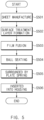
- FIG. 5 is a flowchart illustrating a method for manufacturing the venting device 15 according to an embodiment of the present invention.
- a method for manufacturing the venting device 15 includes: a step (S501) of manufacturing a sheet 152 which is made of a metal, through which a passage 154 passes and in which an edge of an inner circumference of a surface of an outlet-side of the passage 154 is chamfered or filleted; a step (S502) of forming a surface treatment layer 1522 on the chamfered or filleted one surface 1521 of the sheet 152; a step (S503) of fusing a film made of a polymer on the surface treatment layer 1522; and a step (S504) of seating a spherical ball 155 on the fused film.
- the method for manufacturing the venting device 15 may further include: a step (S505) of allowing a plate spring 153 to surround the sheet 152 and the ball 155; and a step (S506) of inserting the sheet 152 and the plate spring 153 into a housing 151 that is inserted between both surfaces of a sealing part 134 so as to be sealed together with the sealing part 134.
- FIG. 6 is a schematic view of the sheet 152 according to an embodiment of the present invention.
- the sheet 152 is formed in the housing 151 and made of a metal. Also, as illustrated in FIG. 6 , in the sheet 152, the edge of the inner circumference of the surface of the outlet-side of the passage 154 is chamfered or filleted. Thus, the ball 155 may be easily closely attached to the chamfered or filleted surface 1521 of the sheet 152. According to an embodiment of the present invention, the surface treatment layer 1522 is formed on the chamfered or filleted surface 1521 of the sheet 152, and then, the polymer film is fused. Thus, the ball 155 closely attached to the sheet 152 may be improved in adhesion to improve sealability when the passage 154 is closed.
- FIG. 7 is a flowchart illustrating a method for forming the surface treatment layer 1522 on the one surface 1521 of the sheet 152 according to an embodiment of the present invention.
- the sheet 152 has a cylinder shape through which the passage 154 passes. Also, if the sheet 152 is made of a polymer, durability may be deteriorated to reduce a lifespan of the venting device 15. Thus, the sheet 152 according to an embodiment of the present invention is made of a metal (S501). Particularly, the metal may include aluminum (Al) or stainless steel (STS). In the sheet 152, the edge of the inner circumference of the surface of the outlet-side of the passage 154 may be chamfered or filleted.
- the sheet 152 may be manufactured through various methods without being limited, for example, a melted metal may be injected into a casting mold in which the passage 154 and the edge of the inner circumference are filled to manufacture the sheet 152.
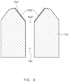
- FIG. 8 is a schematic view illustrating a state in which the surface treatment layer 1522 is formed on the one surface 1521 of the sheet 152 according to an embodiment of the present invention.
- the one surface 1521 of the sheet 152 is debound (S701).
- Various metal processing processes may be performed to manufacture the sheet 152.
- a lubricant is applied to the one surface 1521 of the sheet 152.
- the debinding process is performed to remove the lubricant, the dusts, or other impurities so that the sheet 152 is more efficiently surface-treated.
- the primary washing step (S702) is performed to wash a solution used for the debinding.
- the washing refers to a water cleaning or washing process.
- distilled water in which the impurities are not dissolved is used as the water.
- the metal When the metal is left in air, the metal may be oxidized somewhat to produce an oxidizing material.
- the sheet 152 is made of aluminum, a film made of aluminum oxide may be formed on the one surface 1521 of the sheet 152.
- the etching (S703) is performed to remove the oxidized material produced on the one surface 1521 of the sheet 152.
- the surface treatment may be chromate treatment using chromium.
- the chromate treatment is a kind of chemical film processing in which an insoluble chromate (chromates) film containing a chromium component is thinly formed on the surface of the metal.
- the sheet 152 is immersed in an aqueous solution containing chromium ions.
- the chromium ions undergo oxidation reaction, and the insoluble chromium oxide is generated on the one surface 1521 of the sheet 152 to form a chromate film.
- the surface treatment layer 1522 may be the chromate film containing chromium.
- the chromium ions may be various types of ions without limitation such as hexavalent or trivalent ions.
- the various non-limiting materials such as chromic anhydride, chromium nitrate, chromium sulfate, chromium acetate, and chromium chloride may be used as the aqueous solution containing chromium ions.
- the surface treatment according to another embodiment of the present invention may be non-chromate treatment using a material other than chromium.
- the material other than chromium may be, for example, zirconium. If zirconia treatment using zirconium is performed, the sheet 152 is immersed in an aqueous solution containing the zirconium ions. As a result, the zirconium ions undergo oxidation reaction, and zirconium oxide is generated on the one surface 1521 of the sheet 152 to form a zirconia film.
- the non-chromate treatment is not limited thereto and may include titanium treatment using titanium. That is, according to another embodiment of the present invention, the surface treatment layer 1522 may be the zirconia film containing zirconium or the titanium film containing titanium.
- the tertiary washing step (S706) is performed to wash the solution used for the surface treatment. Also, since the sheet 152 is dried (S707), the surface treatment layer 1522 is formed on the one surface 1521 of the sheet 152 as illustrated in FIG. 8 . As described above, the surface treatment layer 1522 may be formed on the one surface 1521 of the sheet 152 to secure the corrosion resistance and also secure fusibility that the polymer material is well fused to the surface.
- FIG. 9 is a schematic view illustrating a state in which the polymer layer 1523 is laminated on the surface treatment 1522 layer according to an embodiment of the present invention.
- the durability may be deteriorated. If all the ball 155 and the sheet 152 are made of the metal, the gap may occur between the ball 155 and the sheet 152 to deteriorate the sealability. If the polymer film adheres by using an adhesive without performing the surface treatment on the one surface 1521 of the sheet 152, the one surface 1521 of the sheet 152 may increase in thickness by the adhesive. In addition, if the adhesive performance of the adhesive is deteriorated as the venting device 15 is aged as time elapses, the polymer film may be delaminated.
- the surface treatment is performed on the one surface 1521 of the sheet 152 to form the surface treatment layer 1522, and the polymer film is fused to the surface treatment layer 1522 to laminate the polymer layer 1523 (S503).
- a sealing tool for fusing the polymer film has one end that protrudes in a shape corresponding to the one surface 1521 of the sheet 152.
- the polymer film is finely cut and seated on the one end of the sealing tool.
- the one end of the sealing tool contacts the one surface 1521 of the sheet 152.
- the polymer film may be easily seated.
- FIG. 9 when heat and a pressure are applied through the sealing tool, the polymer film may be fused to laminate the polymer layer 1523 on the surface treatment layer 1522.
- the polymer film before the polymer film is fused, the polymer film temporarily adheres to the surface treatment layer 1522 formed on the one surface 1521 of the sheet 152. That is, the polymer film is temporarily attached to the surface treatment layer 1522. Thus, even though the sheet 152 moves along a process line, the polymer film may not move from the sheet 152.
- the temporarily adhering process of the polymer film is performed by applying a pressure of 0.1 MPa to 0.3 MPa for 0.4 seconds to 0.8 seconds under a temperature of 110°C to 130°C. Since the temporary adhesion is a process of temporarily attaching the polymer film, the polymer film has to be easily detached for performing the fusion process later.
- the polymer film may be more strongly attached. Also, if the temporary adhesion is performed under a temperature of 110°C or less, the polymer film may not be properly attached.
- the polymer layer 1523 may be laminated on the surface treatment layer 1522 of the sheet 152.
- the fusion process may be performed under a temperature of 140°C to 220°C. In general, if the temperature is less than 140°C, the polymer film, particularly, the film containing polypropylene may not be sufficiently melted to deteriorate fusibility. Also, if the temperature is greater than 220°C, the polymer film may be excessively melted to be significantly deformed.
- the process of fusing the polymer film may be performed only once, but also may be repeated a plurality of times. If it is repeated three times, the one-time fusion is to remove air bubbles between the surface treatment layer 1522 of the sheet 152 and the polymer film.
- the process of fusing the polymer film may be performed by applying a pressure of 0.1 MPa to 0.3 MPa for 2 seconds to 4 seconds under a temperature of 150°C to 170°C, preferably, 155°C to 165°C. Since the one-time fusion is an initial fusion, it is preferably performed at a temperature of 10°C or more at least higher than 140°C, that is the lowest temperature, to improve the fusibility.
- the temperature is less than 170°C.
- the two-time fusion is to secure the sealability between the one surface 1521 of the sheet 152 and the polymer film.
- the process of fusing the polymer film may be performed by applying a pressure of 0.1 MPa to 0.3 MPa for 2 seconds to 4 seconds under a temperature of 140°C to 170°C, preferably, 145°C to 155°C.
- the two-time fusion may be performed again at a temperature similar to that of the one-time fusion.
- the two-time fusion since the two-time fusion is not the initial fusion, the two-time fusion may be performed at a temperature of 140°C that is the lowest temperature, or more.
- the last three-time fusion is to enhance the fusibility of the polymer film.
- the process of fusing the polymer film may be performed by applying a pressure of 0.1 MPa to 0.3 MPa for 2 seconds to 4 seconds under a temperature of 210°C to 220°C, preferably, 215°C to 220°C. That is, it is preferable that the last three-time fusion is performed at the highest temperature.
- the polymer film may be excessively melted and thus significantly deformed. Also, if the temperature is less than 210°C, the fusibility may not be more enhanced when compared to the fusibility after the two-time fusion is performed.
- the polymer film has a thickness of 100 ⁇ m and includes a polyolefin-based polymer.
- the polymer film may include the acid-treated polyolefin-based polymer.
- the acid-treated polypropylene may be mixed with normal polypropylene, or acid-treated polyethylene may be mixed with the normal polypropylene.
- the polymer film may be simply made of only acid-treated polypropylene.
- the acid-treated polypropylene may be maleic anhydride polypropylene (MAH PP).
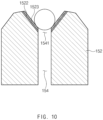
- FIG. 10 is a schematic view illustrating a state in which the ball 155 is seated on the polymer layer 1523 according to an embodiment of the present invention.
- the ball 155 made of a metal is seated on an upper portion of the polymer layer 1523 laminated on the one surface 1521 of the sheet 152 as illustrated in FIG. 10 . Since the edge of the inner circumference of the one surface 1521 of the sheet 152 is chamfered or filleted, the sheet 152 has predetermined slope. Also, since the polymer layer 1523 is laminated on the one surface 1521 of the sheet 152, when the ball 155 is seated, the adhesion between the ball 155 and the sheet 152 may be improved.
- the ball 155 has a diameter less than the widest width of the one surface 1521 of the sheet 152 and larger than the narrowest width of the one surface 1521 of the sheet 152 so that the ball 155 is easily seated on the sheet 152. Also, when the ball 155 is seated, the highest point of the ball 155 is higher than the highest point of the sheet 152. Thus, the ball 155 and the plate spring 153 may easily contact each other, and elastic force of the plate spring 153 may be efficiently applied to the ball 155 so that the ball 155 is closely attached to the sheet 152.
- the sheet 152 and the ball 155 are made of the metal.
- the metal is not flexible, if the metals contact each other, a gap may occur between the ball 155 and the sheet 152 to deteriorate the sealability.
- the polymer layer 1523 is laminated on the one surface 1521 of the sheet 152, the ball 155 is closely attached to the polymer layer 1523 to prevent the gap from occurring, thereby preventing the sealability from being deteriorated.
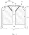
- FIG. 11 is a schematic view illustrating a state in which the plate spring 153 surrounds the sheet 152 and the ball 155 according to an embodiment of the present invention.
- the plate spring 153 is formed to surround the ball 155 and the sheet 152 and has elasticity to open and close the passage 154 together with the ball 155 according to the internal pressure of the pouch.
- a metal plate is formed to manufacture the plate spring 153.
- the metal plate has a wide and thin plate shape and is made of a metal.
- the metal plate may include aluminum (Al) or stainless steel (STS).
- a drawing process of elongating the metal plate by using a punch may be performed to manufacture the plate spring 153.
- the metal plate may be seated on a die, and a stripper may fix the metal plate. Then, the metal plate may be elongated through the punch to perform the drawing.
- one side 1530 that is the uppermost end has a cap shape that is convex outward, and an insertion space into which the sheet 152 is inserted is formed therein.
- the one side 1530 of the plate spring 153 may mean a ceiling of the cap shape as illustrated in FIG. 11 .
- the present invention is not limited thereto.
- the one side 1530 of the plate spring 153 may include various portions.
- the plate spring 153 opens and closes the passage 154 formed in the sheet 152 according to the internal pressure of the pouch.
- a gas exhaust hole 1533 is punched in the one side 1530 of the plate spring 153.
- the one side 1530 of the plate spring 153 includes a central portion 1531 formed in a center thereof and a peripheral portion 1532 extending outward from the central portion 1531.
- a bottom surface of the central portion 1531 of the one side 1530 contacts the ball 155 to close the passage 154 formed in the sheet 152, and thus, the gas exhaust hole 1533 is not punched in the central portion 1531.
- the gas exhaust hole 1533 is punched in the peripheral portion 1532 of the one side 1530 of the plate spring 153.
- the plate spring 153 When the plate spring 153 is manufactured, as illustrated in FIG. 11 , the sheet 152 and the ball 155 are inserted into the insertion space. As a result, the plate spring 153 surrounds the periphery of the sheet 152 and the ball 155. When the sheet 152 and the ball 155 are inserted into the insertion space, it is preferable that the outlet-side of the passage 154 faces the one side 1530 of the plate spring 153. Thus, when the internal pressure of the pouch is less than a specific pressure, the one side 1530 of the plate spring 153 pushes the ball 155 inward from the outlet-side of the passage 154 formed in the sheet 152 to close the passage 154.
- the gas exhaust hole 1533 may be formed in the peripheral portion 1532 of the one side 1530 of the plate spring 153.
- the passage 154 is opened so that the gas leaks to the outlet 1541 of the passage 154.
- the leaking gas has to be discharged to the outside through the gas exhaust hole 1533.
- the edge of the outer circumference of the outlet-side of the passage 154 may be chamfered or filleted.
- the gas may be guided to the gas exhaust hole 1533.
- a space to which the peripheral portion 1532 of the one side 1530 of the plate spring 153 moves inward is provided.
- FIG. 12 is a schematic view illustrating a state in which an end of the other side 1534 of the plate spring 153 is bent toward the sheet 152 according to an embodiment of the present invention.
- the plate spring 153 is firmly fixed to the sheet 152.
- the one side 1530 of the plate spring 153 moves outward.
- the plate spring 153 is not entirely slid, but only one side 1530 of the plate spring 153 is deformed to move. If the plate spring 153 is slid, the plate spring 153 may be separated from the venting device 15. Particularly, only the central portion 1531 of the one side 1530 may be pushed outward, and the peripheral portion 1532 of the one side 1530 may move inward.
- the internal gas of the pouch may be discharged to the outside through the passage 154.
- the end 1534 of the other side of the plate spring 153 is bent toward the sheet 152 as illustrated in FIG. 10 .
- the detachment (separation) of the plate spring 153 from the sheet 152 may be prevented to fix the plate spring 153 to the venting device 15 without separating the plate spring 153 from the venting device 15.
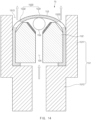
- FIG. 13 is a schematic view illustrating the venting device 15 manufactured by inserting the plate spring 153 and the sheet 152 in FIG. 11 into the housing 151 according to an embodiment of the present invention
- FIG. 14 is an operation diagram illustrating an operation of the venting device 15 according to an embodiment of the present invention.
- the plate spring 153 into which the sheet 152 is inserted is inserted into the housing 151 as illustrated in FIG. 13 .
- the venting device 15 may be completely manufactured.
- the housing 151 includes the upper housing 1511 and the lower housing 1512, it is preferable that the plate spring 153 and the sheet 152 are included in the upper housing 1511.
- the one side 1530 of the plate spring 153 faces an opening end of the upper housing 1511.
- the gas may be discharged to the outside through the gas exhaust hole 1533 formed in the one side 1530.
- the plate spring 153 is not slid as a whole, but only one side 1530 is deformed in the fixed state.
- a gap between the plate spring 153 and the housing 151 is minimized when the plate spring 153 is inserted into the housing 151 so that frictional force acts largely between an outer circumferential surface of the plate spring 153 and an inner circumferential surface of the housing 151.
- the present invention is not limited thereto. In order that the frictional force further increases, surface roughness of the outer circumferential surface of the plate spring 153 or the inner circumferential surface of the housing 151 may increase so that a frictional coefficient increases.
- the plate spring 153 may be fixed to the housing 151 through various methods, for example, a method in which a separate adhesive is applied between the plate spring 153 and the housing 151, or a protrusion protrudes from one of the plate spring 153 and the housing 151, and a groove is formed in the other of the plate spring 153 and the housing 151.
- the venting device 15 manufactured as described above is inserted into the sealing part 134 of the pouch so as to be sealed together. Also, when a gas is generated in the pouch so that an internal pressure of the pouch increases, the gas is discharged to the outside. That is, as described above, when the gas is generated in the pouch, and thus an internal pressure of the pouch gradually increases to exceed a specific pressure, the gas pushes the ball 155 outward as illustrated in FIG. 14 . Also, since the ball 155 is pushed, the one side 1530 of the plate spring 153 is also pushed outward, and thus, the plate spring 153 opens the outlet 1541 of the passage 154. Here, as described above, it is preferable that the plate spring 153 is not slid with respect to the sheet 152.
- the plate spring 153 is made of the metal and thus has the elasticity.
- the plate spring 153 returns to its original position by the elasticity of the plate spring 153.
- the ball 155 is pushed inward from the outlet-side of the passage 154 by the elasticity of the plate spring 153.
- the ball 155 is closely attached to the polymer layer 1523 formed on the one surface 1521 of the sheet 152 to close the passage 154.
Landscapes
- Chemical & Material Sciences (AREA)
- Chemical Kinetics & Catalysis (AREA)
- Electrochemistry (AREA)
- General Chemical & Material Sciences (AREA)
- Engineering & Computer Science (AREA)
- General Engineering & Computer Science (AREA)
- Mechanical Engineering (AREA)
- Inorganic Chemistry (AREA)
- Materials Engineering (AREA)
- Composite Materials (AREA)
- Manufacturing & Machinery (AREA)
- Sealing Battery Cases Or Jackets (AREA)
- Gas Exhaust Devices For Batteries (AREA)
Claims (13)
- Belüftungsvorrichtung (15), welche dazu eingerichtet ist, in einen Dichtungsteil eines Beutels einer Sekundärbatterie eingesetzt zu sein, wobei die Belüftungsvorrichtung umfasst:ein Gehäuse (151), welches dazu eingerichtet ist, zwischen beiden Flächen des Dichtungsteils (134) eingesetzt zu sein und zusammen mit dem Dichtungsteil (134) abgedichtet zu sein;ein Blech (152), welches aus einem Metall hergestellt und in dem Gehäuse (151) gebildet ist, und durch welches ein Durchgang (154) verläuft, welcher der Innenseite und Außenseite des Beutels erlaubt, miteinander zu kommunizieren; undeine Kugel (155), welche das Blech (152) an einer Auslassseite des Durchgangs (154) kontaktiert oder davon beabstandet ist, um den Durchgang (154) zu schließen oder zu öffnen,wobei in dem Blech (152) ein Rand eines inneren Umfangs einer Fläche der Auslassseite des Durchgangs gekeilt oder angeschrägt ist, unddas Blech (152) umfasst:eine Oberflächenbehandlung-Schicht, welche an der gekeilten oder angeschrägten einen Fläche (1521) gebildet ist, um zu der Kugel (155) zu weisen; unddadurch gekennzeichnet, dass die Belüftungsvorrichtung ferner umfasst:eine Polymerschicht (1523), welche aus einem Polymer hergestellt und mit der Oberflächenbehandlung-Schicht fusioniert ist, wobei das Polymer ein säurebehandeltes Polyolefin-basiertes Polymer umfasst, undeine Blattfeder, welche dazu gebildet ist, die Kugel und das Blech (152) zu umgeben, und eine Elastizität aufweist, um den Durchgang zusammen mit der Kugel gemäß einem Innendruck des Beutels zu öffnen und zu schließen.
- Belüftungsvorrichtung nach Anspruch 1, wobei in dem Blech (152) ein Rand eines Außenumfangs der Fläche der Auslassseite des Durchgangs (154) gekeilt oder angeschrägt ist.
- Belüftungsvorrichtung nach Anspruch 1, wobei die Blattfeder eine Seite aufweist, welche eine Kappenform aufweist, welche konvex nach außen ist und einen Einsetzraum bildet, in welchen das Blech (152) darin eingesetzt ist.
- Belüftungsvorrichtung nach Anspruch 3, wobei die eine Seite (1530) der Blattfeder (153) einen zentralen Abschnitt (1531) umfasst, welcher an einem Zentrum davon gebildet ist, sowie einen Umfangsabschnitt (1532), welcher sich von dem zentralen Abschnitt (1531) nach außen erstreckt, und
ein Gas-Ausgabeloch (1533) in den Umfangsabschnitt (1532) der Blattfeder (153) gestanzt ist. - Belüftungsvorrichtung nach Anspruch 3, wobei ein Ende der anderen Seite der Blattfeder in Richtung des Blechs gebogen ist, welches in den Einsetzraum eingesetzt ist.
- Belüftungsvorrichtung nach Anspruch 1, wobei das Metall Aluminium oder Edelstahl umfasst.
- Belüftungsvorrichtung nach Anspruch 1, wobei die Oberflächenbehandlung-Schicht (1522) wenigstens eines aus Chrom, Zirkonium und Titan umfasst.
- Belüftungsvorrichtung nach Anspruch 1, wobei das Gehäuse ein oberes Gehäuse (1511) und ein unteres Gehäuse (1512) umfasst, welche voneinander verschiedene Formen oder Größen aufweisen.
- Belüftungsvorrichtung nach Anspruch 8, wobei das untere Gehäuse (1512) eine Breite aufweist, welche geringer als diejenige des oberen Gehäuses (1511) ist.
- Belüftungsvorrichtung nach Anspruch 8, wobei das obere Gehäuse (1511) eine kreiszylindrische Form aufweist, und
das untere Gehäuse (1512) eine ovale Zylinderform aufweist. - Verfahren zum Herstellen einer Belüftungsvorrichtung nach einem der Ansprüche 1 bis 10, wobei das Verfahren umfasst:einen Schritt eines Herstellens eines Blechs, welches aus einem Metall hergestellt ist, durch welches ein Durchgang verläuft, und in welchem ein Rand eines Innenumfangs einer Fläche einer Auslassseite des Durchgangs gekeilt oder angeschrägt ist;einen Schritt eines Bildens einer Oberflächenbehandlung-Schicht, welche an der gekeilten oder angeschrägten einen Fläche des Blechs gebildet wird;einen Schritt eines Fusionierens eines aus einem Polymer hergestellten Films an die Oberflächenbehandlung-Schicht; undeinen Schritt eines Einsetzens einer Kugel mit einer kugelförmigen Form an den fusionierten Film.
- Verfahren nach Anspruch 11, wobei der Schritt des Bildens der Oberflächenbehandlung-Schicht umfasst:einen Schritt eines Entbinderns der Metallplatte;einen primären Waschschritt;einen Ätzschritt;einen sekundären Waschschritt;einen Oberflächenbehandlung-Schritt;einen tertiären Waschschritt; undeinen Trocknungsschritt.
- Verfahren nach Anspruch 11, nach dem Schritt des Einsetzens der Kugel ferner umfassend:einen Schritt eines Erlaubens einer Blattfeder mit einer Kappenform, das Blech und die Kugel zu umgeben; undeinen Schritt eines Einsetzens des Blechs in ein Gehäuse, welches zwischen beiden Flächen des Dichtungsteils eingesetzt wird, um so zusammen mit dem Dichtungsteil abgedichtet zu werden.
Applications Claiming Priority (3)
| Application Number | Priority Date | Filing Date | Title |
|---|---|---|---|
| KR1020180053797A KR102341465B1 (ko) | 2018-05-10 | 2018-05-10 | 벤팅 장치 및 그의 제조 방법 |
| EP19800490.5A EP3651235B1 (de) | 2018-05-10 | 2019-01-23 | Entlüftungsvorrichtung und verfahren zu deren herstellung |
| PCT/KR2019/000972 WO2019216520A1 (ko) | 2018-05-10 | 2019-01-23 | 벤팅 장치 및 그의 제조 방법 |
Related Parent Applications (2)
| Application Number | Title | Priority Date | Filing Date |
|---|---|---|---|
| EP19800490.5A Division-Into EP3651235B1 (de) | 2018-05-10 | 2019-01-23 | Entlüftungsvorrichtung und verfahren zu deren herstellung |
| EP19800490.5A Division EP3651235B1 (de) | 2018-05-10 | 2019-01-23 | Entlüftungsvorrichtung und verfahren zu deren herstellung |
Publications (3)
| Publication Number | Publication Date |
|---|---|
| EP4353618A2 EP4353618A2 (de) | 2024-04-17 |
| EP4353618A3 EP4353618A3 (de) | 2024-05-15 |
| EP4353618B1 true EP4353618B1 (de) | 2025-04-16 |
Family
ID=68467487
Family Applications (2)
| Application Number | Title | Priority Date | Filing Date |
|---|---|---|---|
| EP24159325.0A Active EP4353618B1 (de) | 2018-05-10 | 2019-01-23 | Entlüftungsvorrichtung und verfahren zur herstellung davon |
| EP19800490.5A Active EP3651235B1 (de) | 2018-05-10 | 2019-01-23 | Entlüftungsvorrichtung und verfahren zu deren herstellung |
Family Applications After (1)
| Application Number | Title | Priority Date | Filing Date |
|---|---|---|---|
| EP19800490.5A Active EP3651235B1 (de) | 2018-05-10 | 2019-01-23 | Entlüftungsvorrichtung und verfahren zu deren herstellung |
Country Status (9)
| Country | Link |
|---|---|
| US (1) | US11539098B2 (de) |
| EP (2) | EP4353618B1 (de) |
| JP (1) | JP7034408B2 (de) |
| KR (1) | KR102341465B1 (de) |
| CN (1) | CN110998909B (de) |
| ES (2) | ES2985263T3 (de) |
| HU (2) | HUE066394T2 (de) |
| PL (1) | PL4353618T3 (de) |
| WO (1) | WO2019216520A1 (de) |
Families Citing this family (9)
| Publication number | Priority date | Publication date | Assignee | Title |
|---|---|---|---|---|
| KR102164254B1 (ko) * | 2017-11-15 | 2020-10-12 | 주식회사 엘지화학 | 이차 전지 및 그의 제조 방법, 이차 전지용 파우치 및 그의 제조 방법 |
| JP6996422B2 (ja) * | 2018-05-28 | 2022-02-21 | 大日本印刷株式会社 | 電池 |
| CN110828879A (zh) * | 2019-11-20 | 2020-02-21 | 苏州易来科得科技有限公司 | 一种电池化成的排气装置、排气方法以及电池化成的方法 |
| KR102332931B1 (ko) * | 2019-11-29 | 2021-11-30 | 한국제이씨씨(주) | 고전압용 캔형 전기 이중층 커패시터 |
| JP7464309B2 (ja) * | 2020-07-13 | 2024-04-09 | エルジー エナジー ソリューション リミテッド | バッテリバルブ及びこれを含むバッテリ |
| KR102807591B1 (ko) * | 2020-07-14 | 2025-05-13 | 주식회사 엘지에너지솔루션 | 벤팅 디바이스 및 이를 포함하는 배터리 팩 어셈블리, 그리고 배터리 팩 어셈블리를 포함하는 자동차 |
| CN113314799B (zh) * | 2021-06-07 | 2022-09-27 | 江苏天辉锂电池有限公司 | 一种锂电池 |
| KR102935497B1 (ko) * | 2021-07-14 | 2026-03-06 | 주식회사 엘지에너지솔루션 | 벤팅 장치 및 이를 포함하는 배터리 모듈 |
| JP2025526497A (ja) * | 2022-08-09 | 2025-08-13 | エルジー エナジー ソリューション リミテッド | 電池缶の注液口のシール構造、これを適用したバッテリセル、バッテリパック及び自動車 |
Family Cites Families (19)
| Publication number | Priority date | Publication date | Assignee | Title |
|---|---|---|---|---|
| EP1102336B1 (de) | 1999-04-08 | 2007-09-12 | Dai Nippon Printing Co., Ltd. | Multischicht-verbundstruktur zum packen einer lithiumzelle |
| FR2815691B1 (fr) | 2000-10-20 | 2003-08-15 | Valois Sa | Bille de clapet |
| JP2003068269A (ja) | 2001-08-28 | 2003-03-07 | Sanyo Electric Co Ltd | 密閉型蓄電池 |
| JP2005322576A (ja) * | 2004-05-11 | 2005-11-17 | Sanyo Electric Co Ltd | 密閉二次電池 |
| JP4867158B2 (ja) * | 2004-11-19 | 2012-02-01 | トヨタ自動車株式会社 | フィルム外装型蓄電装置 |
| US8071231B2 (en) | 2006-08-28 | 2011-12-06 | Lg Chem, Ltd. | Secondary battery including one-way exhaust valve |
| TWI421428B (zh) | 2007-02-05 | 2014-01-01 | American Pneumatic Tools Inc | 具有球閥之連續行程氣動工具 |
| JP5025277B2 (ja) * | 2007-02-13 | 2012-09-12 | 株式会社東芝 | 電池の製造方法 |
| JP2010135247A (ja) * | 2008-12-08 | 2010-06-17 | Panasonic Corp | 密閉型電池、接続部材付き電池及び組電池 |
| CN201353106Y (zh) * | 2009-02-17 | 2009-12-02 | 曹永祥 | 防炸暖瓶塞 |
| US8383255B2 (en) * | 2009-02-24 | 2013-02-26 | Eveready Battery Company, Inc. | Closure assembly for electrochemical cells |
| JP2011001892A (ja) * | 2009-06-19 | 2011-01-06 | Nikki Co Ltd | インジェクタ |
| EP2709191A4 (de) * | 2012-03-28 | 2015-08-19 | Optnics Prec Co Ltd | Sicherheitsventil und elektrochemisches element |
| KR101753213B1 (ko) | 2013-11-28 | 2017-07-19 | 주식회사 엘지화학 | 배터리 셀, 그리고 이를 포함하는 배터리 모듈 및 배터리 팩 |
| KR102275273B1 (ko) * | 2014-07-29 | 2021-07-09 | 에스케이이노베이션 주식회사 | 파우치형 리튬 이차전지의 벤팅 시스템 |
| KR101768656B1 (ko) * | 2014-10-31 | 2017-08-16 | 주식회사 엘지화학 | 캡 조립체 및 이를 포함하는 이차 전지 |
| KR101858317B1 (ko) * | 2015-05-07 | 2018-05-15 | 주식회사 엘지화학 | 전류 제한 기능의 전극리드를 포함하는 파우치형 이차전지 |
| KR20170000070A (ko) | 2015-06-23 | 2017-01-02 | 김한섭 | Vrla 배터리용 마개 |
| KR102361569B1 (ko) * | 2018-04-23 | 2022-02-10 | 주식회사 엘지에너지솔루션 | 가스배출수단이 구비된 파우치형 이차전지 |
-
2018
- 2018-05-10 KR KR1020180053797A patent/KR102341465B1/ko active Active
-
2019
- 2019-01-23 US US16/637,538 patent/US11539098B2/en active Active
- 2019-01-23 WO PCT/KR2019/000972 patent/WO2019216520A1/ko not_active Ceased
- 2019-01-23 HU HUE19800490A patent/HUE066394T2/hu unknown
- 2019-01-23 EP EP24159325.0A patent/EP4353618B1/de active Active
- 2019-01-23 JP JP2020506200A patent/JP7034408B2/ja active Active
- 2019-01-23 CN CN201980003703.0A patent/CN110998909B/zh active Active
- 2019-01-23 ES ES19800490T patent/ES2985263T3/es active Active
- 2019-01-23 EP EP19800490.5A patent/EP3651235B1/de active Active
- 2019-01-23 PL PL24159325.0T patent/PL4353618T3/pl unknown
- 2019-01-23 ES ES24159325T patent/ES3031888T3/es active Active
- 2019-01-23 HU HUE24159325A patent/HUE072052T2/hu unknown
Also Published As
| Publication number | Publication date |
|---|---|
| JP2020529717A (ja) | 2020-10-08 |
| PL4353618T3 (pl) | 2025-06-16 |
| HUE066394T2 (hu) | 2024-07-28 |
| EP3651235B1 (de) | 2024-04-17 |
| EP4353618A3 (de) | 2024-05-15 |
| US11539098B2 (en) | 2022-12-27 |
| CN110998909B (zh) | 2022-05-17 |
| HUE072052T2 (hu) | 2025-10-28 |
| WO2019216520A1 (ko) | 2019-11-14 |
| EP3651235A1 (de) | 2020-05-13 |
| EP3651235A4 (de) | 2020-10-21 |
| KR20190129326A (ko) | 2019-11-20 |
| JP7034408B2 (ja) | 2022-03-14 |
| US20200259146A1 (en) | 2020-08-13 |
| ES3031888T3 (en) | 2025-07-11 |
| EP4353618A2 (de) | 2024-04-17 |
| KR102341465B1 (ko) | 2021-12-22 |
| CN110998909A (zh) | 2020-04-10 |
| ES2985263T3 (es) | 2024-11-04 |
Similar Documents
| Publication | Publication Date | Title |
|---|---|---|
| EP4353618B1 (de) | Entlüftungsvorrichtung und verfahren zur herstellung davon | |
| KR102519040B1 (ko) | 벤팅 장치, 벤팅 방법 및 이차 전지 | |
| EP3754750B1 (de) | Entlüftungsvorrichtung | |
| US11881591B2 (en) | Venting device and method for manufacturing the same | |
| CN114175380B (zh) | 二次电池 | |
| EP3182486B1 (de) | Wiederaufladbare batterie | |
| KR102495134B1 (ko) | 벤팅 장치 및 그의 제조 방법 | |
| KR102386323B1 (ko) | 벤팅 장치 및 그의 제조 방법 | |
| US20240145853A1 (en) | Secondary battery |
Legal Events
| Date | Code | Title | Description |
|---|---|---|---|
| PUAI | Public reference made under article 153(3) epc to a published international application that has entered the european phase |
Free format text: ORIGINAL CODE: 0009012 |
|
| STAA | Information on the status of an ep patent application or granted ep patent |
Free format text: STATUS: REQUEST FOR EXAMINATION WAS MADE |
|
| PUAL | Search report despatched |
Free format text: ORIGINAL CODE: 0009013 |
|
| 17P | Request for examination filed |
Effective date: 20240223 |
|
| AC | Divisional application: reference to earlier application |
Ref document number: 3651235 Country of ref document: EP Kind code of ref document: P |
|
| AK | Designated contracting states |
Kind code of ref document: A2 Designated state(s): AL AT BE BG CH CY CZ DE DK EE ES FI FR GB GR HR HU IE IS IT LI LT LU LV MC MK MT NL NO PL PT RO RS SE SI SK SM TR |
|
| AK | Designated contracting states |
Kind code of ref document: A3 Designated state(s): AL AT BE BG CH CY CZ DE DK EE ES FI FR GB GR HR HU IE IS IT LI LT LU LV MC MK MT NL NO PL PT RO RS SE SI SK SM TR |
|
| RIC1 | Information provided on ipc code assigned before grant |
Ipc: H01M 50/35 20210101ALI20240410BHEP Ipc: H01M 50/325 20210101ALI20240410BHEP Ipc: H01M 50/317 20210101ALI20240410BHEP Ipc: H01M 50/30 20210101ALI20240410BHEP Ipc: H01M 50/126 20210101ALI20240410BHEP Ipc: H01M 50/122 20210101ALI20240410BHEP Ipc: H01M 50/121 20210101ALI20240410BHEP Ipc: H01M 50/119 20210101ALI20240410BHEP Ipc: H01M 50/105 20210101ALI20240410BHEP Ipc: H01M 10/052 20100101ALI20240410BHEP Ipc: F16K 17/04 20060101ALI20240410BHEP Ipc: B65D 51/16 20060101ALI20240410BHEP Ipc: B65D 75/22 20060101AFI20240410BHEP |
|
| GRAP | Despatch of communication of intention to grant a patent |
Free format text: ORIGINAL CODE: EPIDOSNIGR1 |
|
| STAA | Information on the status of an ep patent application or granted ep patent |
Free format text: STATUS: GRANT OF PATENT IS INTENDED |
|
| INTG | Intention to grant announced |
Effective date: 20241218 |
|
| P01 | Opt-out of the competence of the unified patent court (upc) registered |
Free format text: CASE NUMBER: APP_599/2025 Effective date: 20250107 |
|
| GRAS | Grant fee paid |
Free format text: ORIGINAL CODE: EPIDOSNIGR3 |
|
| GRAA | (expected) grant |
Free format text: ORIGINAL CODE: 0009210 |
|
| STAA | Information on the status of an ep patent application or granted ep patent |
Free format text: STATUS: THE PATENT HAS BEEN GRANTED |
|
| AC | Divisional application: reference to earlier application |
Ref document number: 3651235 Country of ref document: EP Kind code of ref document: P |
|
| AK | Designated contracting states |
Kind code of ref document: B1 Designated state(s): AL AT BE BG CH CY CZ DE DK EE ES FI FR GB GR HR HU IE IS IT LI LT LU LV MC MK MT NL NO PL PT RO RS SE SI SK SM TR |
|
| REG | Reference to a national code |
Ref country code: GB Ref legal event code: FG4D |
|
| REG | Reference to a national code |
Ref country code: CH Ref legal event code: EP Ref country code: DE Ref legal event code: R096 Ref document number: 602019068915 Country of ref document: DE |
|
| REG | Reference to a national code |
Ref country code: IE Ref legal event code: FG4D |
|
| REG | Reference to a national code |
Ref country code: SE Ref legal event code: TRGR |
|
| REG | Reference to a national code |
Ref country code: ES Ref legal event code: FG2A Ref document number: 3031888 Country of ref document: ES Kind code of ref document: T3 Effective date: 20250711 |
|
| REG | Reference to a national code |
Ref country code: NL Ref legal event code: FP |
|
| REG | Reference to a national code |
Ref country code: AT Ref legal event code: MK05 Ref document number: 1785512 Country of ref document: AT Kind code of ref document: T Effective date: 20250416 |
|
| PG25 | Lapsed in a contracting state [announced via postgrant information from national office to epo] |
Ref country code: PT Free format text: LAPSE BECAUSE OF FAILURE TO SUBMIT A TRANSLATION OF THE DESCRIPTION OR TO PAY THE FEE WITHIN THE PRESCRIBED TIME-LIMIT Effective date: 20250818 Ref country code: FI Free format text: LAPSE BECAUSE OF FAILURE TO SUBMIT A TRANSLATION OF THE DESCRIPTION OR TO PAY THE FEE WITHIN THE PRESCRIBED TIME-LIMIT Effective date: 20250416 |
|
| REG | Reference to a national code |
Ref country code: LT Ref legal event code: MG9D |
|
| PG25 | Lapsed in a contracting state [announced via postgrant information from national office to epo] |
Ref country code: NO Free format text: LAPSE BECAUSE OF FAILURE TO SUBMIT A TRANSLATION OF THE DESCRIPTION OR TO PAY THE FEE WITHIN THE PRESCRIBED TIME-LIMIT Effective date: 20250716 Ref country code: GR Free format text: LAPSE BECAUSE OF FAILURE TO SUBMIT A TRANSLATION OF THE DESCRIPTION OR TO PAY THE FEE WITHIN THE PRESCRIBED TIME-LIMIT Effective date: 20250717 |
|
| PG25 | Lapsed in a contracting state [announced via postgrant information from national office to epo] |
Ref country code: BG Free format text: LAPSE BECAUSE OF FAILURE TO SUBMIT A TRANSLATION OF THE DESCRIPTION OR TO PAY THE FEE WITHIN THE PRESCRIBED TIME-LIMIT Effective date: 20250416 |
|
| PG25 | Lapsed in a contracting state [announced via postgrant information from national office to epo] |
Ref country code: HR Free format text: LAPSE BECAUSE OF FAILURE TO SUBMIT A TRANSLATION OF THE DESCRIPTION OR TO PAY THE FEE WITHIN THE PRESCRIBED TIME-LIMIT Effective date: 20250416 |
|
| PG25 | Lapsed in a contracting state [announced via postgrant information from national office to epo] |
Ref country code: AT Free format text: LAPSE BECAUSE OF FAILURE TO SUBMIT A TRANSLATION OF THE DESCRIPTION OR TO PAY THE FEE WITHIN THE PRESCRIBED TIME-LIMIT Effective date: 20250416 |
|
| PG25 | Lapsed in a contracting state [announced via postgrant information from national office to epo] |
Ref country code: RS Free format text: LAPSE BECAUSE OF FAILURE TO SUBMIT A TRANSLATION OF THE DESCRIPTION OR TO PAY THE FEE WITHIN THE PRESCRIBED TIME-LIMIT Effective date: 20250716 |
|
| PG25 | Lapsed in a contracting state [announced via postgrant information from national office to epo] |
Ref country code: IS Free format text: LAPSE BECAUSE OF FAILURE TO SUBMIT A TRANSLATION OF THE DESCRIPTION OR TO PAY THE FEE WITHIN THE PRESCRIBED TIME-LIMIT Effective date: 20250816 |
|
| REG | Reference to a national code |
Ref country code: HU Ref legal event code: AG4A Ref document number: E072052 Country of ref document: HU |
|
| PG25 | Lapsed in a contracting state [announced via postgrant information from national office to epo] |
Ref country code: LV Free format text: LAPSE BECAUSE OF FAILURE TO SUBMIT A TRANSLATION OF THE DESCRIPTION OR TO PAY THE FEE WITHIN THE PRESCRIBED TIME-LIMIT Effective date: 20250416 |
|
| PGFP | Annual fee paid to national office [announced via postgrant information from national office to epo] |
Ref country code: GB Payment date: 20251222 Year of fee payment: 8 |
|
| PG25 | Lapsed in a contracting state [announced via postgrant information from national office to epo] |
Ref country code: DK Free format text: LAPSE BECAUSE OF FAILURE TO SUBMIT A TRANSLATION OF THE DESCRIPTION OR TO PAY THE FEE WITHIN THE PRESCRIBED TIME-LIMIT Effective date: 20250416 Ref country code: SM Free format text: LAPSE BECAUSE OF FAILURE TO SUBMIT A TRANSLATION OF THE DESCRIPTION OR TO PAY THE FEE WITHIN THE PRESCRIBED TIME-LIMIT Effective date: 20250416 |
|
| PGFP | Annual fee paid to national office [announced via postgrant information from national office to epo] |
Ref country code: FR Payment date: 20251223 Year of fee payment: 8 Ref country code: NL Payment date: 20251223 Year of fee payment: 8 |
|
| PGFP | Annual fee paid to national office [announced via postgrant information from national office to epo] |
Ref country code: BE Payment date: 20251229 Year of fee payment: 8 |
|
| PGFP | Annual fee paid to national office [announced via postgrant information from national office to epo] |
Ref country code: SE Payment date: 20251223 Year of fee payment: 8 |
|
| REG | Reference to a national code |
Ref country code: DE Ref legal event code: R097 Ref document number: 602019068915 Country of ref document: DE |
|
| PG25 | Lapsed in a contracting state [announced via postgrant information from national office to epo] |
Ref country code: CZ Free format text: LAPSE BECAUSE OF FAILURE TO SUBMIT A TRANSLATION OF THE DESCRIPTION OR TO PAY THE FEE WITHIN THE PRESCRIBED TIME-LIMIT Effective date: 20250416 |
|
| PG25 | Lapsed in a contracting state [announced via postgrant information from national office to epo] |
Ref country code: EE Free format text: LAPSE BECAUSE OF FAILURE TO SUBMIT A TRANSLATION OF THE DESCRIPTION OR TO PAY THE FEE WITHIN THE PRESCRIBED TIME-LIMIT Effective date: 20250416 |
|
| PG25 | Lapsed in a contracting state [announced via postgrant information from national office to epo] |
Ref country code: SK Free format text: LAPSE BECAUSE OF FAILURE TO SUBMIT A TRANSLATION OF THE DESCRIPTION OR TO PAY THE FEE WITHIN THE PRESCRIBED TIME-LIMIT Effective date: 20250416 |
|
| PLBE | No opposition filed within time limit |
Free format text: ORIGINAL CODE: 0009261 |
|
| STAA | Information on the status of an ep patent application or granted ep patent |
Free format text: STATUS: NO OPPOSITION FILED WITHIN TIME LIMIT |
|
| REG | Reference to a national code |
Ref country code: CH Ref legal event code: L10 Free format text: ST27 STATUS EVENT CODE: U-0-0-L10-L00 (AS PROVIDED BY THE NATIONAL OFFICE) Effective date: 20260225 |
|
| 26N | No opposition filed |
Effective date: 20260119 |
|
| PGFP | Annual fee paid to national office [announced via postgrant information from national office to epo] |
Ref country code: ES Payment date: 20260212 Year of fee payment: 8 |
|
| PGFP | Annual fee paid to national office [announced via postgrant information from national office to epo] |
Ref country code: DE Payment date: 20251222 Year of fee payment: 8 |
|
| PGFP | Annual fee paid to national office [announced via postgrant information from national office to epo] |
Ref country code: IT Payment date: 20251223 Year of fee payment: 8 |
|
| PGFP | Annual fee paid to national office [announced via postgrant information from national office to epo] |
Ref country code: TR Payment date: 20260108 Year of fee payment: 8 |
|
| PGFP | Annual fee paid to national office [announced via postgrant information from national office to epo] |
Ref country code: PL Payment date: 20251229 Year of fee payment: 8 |