EP4353646A1 - Système de levage de plate-forme - Google Patents
Système de levage de plate-forme Download PDFInfo
- Publication number
- EP4353646A1 EP4353646A1 EP22200578.7A EP22200578A EP4353646A1 EP 4353646 A1 EP4353646 A1 EP 4353646A1 EP 22200578 A EP22200578 A EP 22200578A EP 4353646 A1 EP4353646 A1 EP 4353646A1
- Authority
- EP
- European Patent Office
- Prior art keywords
- drive
- platform
- toothed belt
- belt
- deflection wheels
- Prior art date
- Legal status (The legal status is an assumption and is not a legal conclusion. Google has not performed a legal analysis and makes no representation as to the accuracy of the status listed.)
- Withdrawn
Links
Images




Classifications
-
- B—PERFORMING OPERATIONS; TRANSPORTING
- B66—HOISTING; LIFTING; HAULING
- B66B—ELEVATORS; ESCALATORS OR MOVING WALKWAYS
- B66B9/00—Kinds or types of lifts in, or associated with, buildings or other structures
- B66B9/06—Kinds or types of lifts in, or associated with, buildings or other structures inclined, e.g. serving blast furnaces
- B66B9/08—Kinds or types of lifts in, or associated with, buildings or other structures inclined, e.g. serving blast furnaces associated with stairways, e.g. for transporting disabled persons
- B66B9/0853—Lifting platforms, e.g. constructional features
-
- B—PERFORMING OPERATIONS; TRANSPORTING
- B66—HOISTING; LIFTING; HAULING
- B66B—ELEVATORS; ESCALATORS OR MOVING WALKWAYS
- B66B11/00—Main component parts of lifts in, or associated with, buildings or other structures
- B66B11/04—Driving gear ; Details thereof, e.g. seals
- B66B11/043—Driving gear ; Details thereof, e.g. seals actuated by rotating motor; Details, e.g. ventilation
- B66B11/0469—Driving gear ; Details thereof, e.g. seals actuated by rotating motor; Details, e.g. ventilation with chain, pinion gear
-
- B—PERFORMING OPERATIONS; TRANSPORTING
- B66—HOISTING; LIFTING; HAULING
- B66B—ELEVATORS; ESCALATORS OR MOVING WALKWAYS
- B66B11/00—Main component parts of lifts in, or associated with, buildings or other structures
- B66B11/0035—Arrangement of driving gear, e.g. location or support
- B66B11/0045—Arrangement of driving gear, e.g. location or support in the hoistway
-
- B—PERFORMING OPERATIONS; TRANSPORTING
- B66—HOISTING; LIFTING; HAULING
- B66B—ELEVATORS; ESCALATORS OR MOVING WALKWAYS
- B66B7/00—Other common features of elevators
- B66B7/06—Arrangements of ropes or cables
- B66B7/062—Belts
Definitions
- the present invention relates to a platform lifting system for transporting a person or an object from at least a first level to a second level, wherein the lifting system comprises a compact drive system with a toothed belt and a belt drive.
- an improved lifting system and method for moving a platform of a platform lifting system from a first level to second level would be advantageous, and in particular, a more efficient, reliable and/or modifiable, adaptable and compact platform lifting system and method would be advantageous.
- a platform lifting system for transporting a person or an object from at least a first level to a second level, wherein the platform lifting system comprises:
- the invention is particularly, but not exclusively, advantageous for obtaining a compact lifting system, where the potential positions of the platform lifting system are not limited to specific locations inside or outside a building.
- the platform lifting systems of the invention can easily and reliable be mounted outside or inside already existing buildings without the need of modifying the building and/or architecture.
- a belt drive is installed to drive the movement of the lift.
- the belt drive is taking space in the columns requiring columns of a certain depth. Therefore, a compact belt drive is preferred to limiting the requirements to the depth of the columns.
- the platform lifting system providing the opportunity of mounting the belt drive in a column, allows the lifting system to be mounted without the necessity of making room for the belt drive in the floor or in the ceiling of an associated building e.g. by making a hole in the floor or ceiling.
- the drive unit may be mounted vertically anywhere between the columns in a position, where the drive unit does not interfere with doors, access openings or windows.
- the drive unit is connected to the belt drive, to drive the drive wheel.
- the lifting system can be mounted at any desirable site inside or outside a building without the need of breaking or demolishing anything, such as making a hole for obtaining room for the belt drive and the drive unit.
- the embodiment is particularly, but not exclusively, advantageous for obtaining a platform lifting system providing an easily accessible belt drive, so that the service and maintenance of the lifting system is made a lot more convenient and effective.
- a first level and a second level it is to be understood as two floors, which can be any floor in the building, and is not necessarily to be understood as the first floor and the second floor.
- the platform moving up is the platform moving up:
- the platform may be able to move from more than only two levels. Such that the platform can also move to a third, fourth, fifth, sixth, etc. level within the context of the invention.
- the platform is moving between at least two levels, however no upper limit of levels should define the scope of the invention.
- a drive unit drives the belt drive.
- the drive unit preferably comprises a least:
- closed end system may be understood as a drive system comprising an endless configuration, such as a closed end belt system with an endless belt.
- a belt or the like can be connected at its ends via a connecting element, preferably a laser-cut steel tube or another kind of tube or the like.
- the platform is connected to the endless belt at the connecting element.
- the belt is via the connecting element "endless" in the sense that the ends are fixed in the same tube, and the ends can therefore not move in relation to each other.
- belt drive may be understood as a drive that drives the toothed belt; the drive wheel in the belt drive is engaging the toothed belt and moving the toothed belt, which is an endless belt.
- the toothed belt is connected to the platform, pulling the platform up or lowers the platform as the toothed belt is moved by the drive wheel in the belt drive.
- the drive wheel is connected to the drive unit, which are driving the drive wheel.
- the drive wheel can move in both directions either pulling the toothed belt one way or the other way, raising or lowering the platform.
- They diameter of the drive wheel may be only slightly smaller than the depth of the frame. For instance, the depth of the drive wheel may be less than 10 % smaller than the depth of the frame. If the depth of the frame may be, for instance, 140 mm, the diameter of the drive wheel may be 120-130 mm.
- each set of deflection wheels comprises a number of small deflection wheels; there may be 3-10 deflection wheels.
- the diameter of each deflection wheel may be less than 1/10, less than 1/8, less than 1/7, less than 1/6 of the diameter of the drive wheel.
- the requirements to the toothed belt is quite high, and also the drive system and the belt drive must be able to carry a considerable weight.
- the toothed belt When carrying a high weight the toothed belt must be rigid enough not to be drawn to be longer. At the same time, the toothed belt must be flexible enough the engage with the drive wheel.
- the advantage, of the belt drive having deflection wheels gradually allowing the toothed belt to deflect its direction, is that even a rigid toothed belt can be deflected to engage the drive wheel.
- the drive system may comprises two toothed belts and two corresponding belt drives.
- One toothed belt and one belt drive mounted in each of the two vertical columns.
- the same drive unit placed between the two columns may drive both the belt drives.
- the drive wheel, the first set of the plurality of deflection wheels and the second set of the plurality of deflection wheels displaces the toothed belt so that the first opening, where the toothed belt enters a frame, and the second opening, where the toothed belt leaves the frame, are positioned on a line substantially parallel with the up and down moving direction of the platform.
- the toothed belt is moving around in a closed loop, basically with the toothed belt moving up in one plane parallel with the up and down moving direction of the platform and down in another plane also parallel with the up and down moving direction of the platform.
- the toothed belt is pulled through the belt drive by the drive wheel, the toothed belt is displaced by the first set of deflection wheels away from the parallel plane to engage with the drive wheel.
- the second set of the plurality of deflection wheels displaces the toothed belt back to the original parallel plan.
- frame may be understood as a structure, which holds the drive wheel and the deflection wheels. It may be a relative open structure, with a first opening and a second opening. The first opening and the second opening are passages allowing the toothed belt to move into and out of the belt drive.
- the toothed belt when passing through the frame the toothed belt may move in many different directions as the toothed belt is deflected or displaced by the first set of deflection wheels, the drive wheel and the second set of deflection wheels.
- the first direction and the second direction of the toothed belt substantially is in the same direction.
- the toothed belt enters the frame and leaves the frame moving in the same direction. That is to be understood, as the toothed belt is moving in the same direction, when it leaves the frame, as it moved in, when it entered the frame. However, between entering the frame and leaving the frame the toothed belt has been deflected or displaced first by the first set of deflection wheels, then by the drive wheel and finally by the second set of deflection wheels.
- the toothed belt may move in a different direction when it leaves the frame. For instance, if the frame is placed in a corner of a column, then the toothed belt may leave the frame in a direction perpendicular to the direction it moved in when it entered the frame.
- the drive wheel, at least the majority of the first set of the plurality of deflection wheels and/or at least the majority of the second set of the plurality of deflection wheels are placed between two parallel lines, which are tangents to the drive wheel in parallel with the up and down moving direction of the platform.
- the first and second set of the plurality of deflection wheels substantially are placed besides the drive wheel.
- the majority, preferably all, of the plurality of deflections wheels are placed between those two parallel lines.
- the advantage is that the plurality of deflection wheels substantially do not require more space in the direction perpendicular to the direction of movement of the platform than the drive wheel requires. Thereby a compact belt drive is acquired, which does not take more space perpendicular to the direction of movement of the platform in the columns than absolutely needed.
- the depth of the frame is less than 130%, more preferable less than 120%, and even more preferable less than 110% of the diameter of the drive wheel.
- the depth of the frame containing the drive wheel and the first and second set of the plurality of deflection wheels may only be slightly deeper than the diameter of the drive wheel.
- the at least two columns are mounted on a wall or a floor deck of an associated building.
- the embodiment is particularly, but not exclusively, advantageous for obtaining a lifting system that can be mounted on any suitable wall of an associated building or on a floor deck of an associated building and thereby more or less on any desirable place in or on a building.
- the wall can be either an inside wall or an outside wall.
- the type of wall of floor deck should not be limiting for the invention; however, the wall construction should be suitable for bearing some weight of the lifting system.
- the depth of the belt drive is less than the depth of the vertical columns, preferable less than half the depth of the columns.
- the belt drive is placed in the vertical columns and is made so compact that the depth of the columns can be minimized to contain the belt drive in the column.
- the first set of the plurality of deflection wheels are fixed at fixing points that are points on a substantially continuous curve and/or the second set of the plurality of deflection wheels are fixed at fixing points that are points on a substantially continuous curve.
- Locating the first set of the plurality of deflection wheels on a substantially continuous curve has the advantage to minimize the strain on the toothed belt when it is deflected from the direction of movement to engage the drive wheel.
- the continuous curve may be a partial circle, a partial oval, or the curve defined by a polynomial.
- the first set of the plurality of deflection wheels are fixed at fixing points that are points on a partial circle, wherein the radius of the partial circle is larger than the radius of the drive wheel.
- the curve, whereon the fixing points are placed are a circle curve, where the radius of the partial circle is larger than the radius of the drive wheel. This ensures a smooth deflection of the toothed belt from the direction it is moving to engage the drive wheel.
- the second set of the plurality of deflection wheels are fixed at fixing points that are points on a partial circle, wherein the radius of the partial circle is larger than the radius of the drive wheel.
- the drive unit is mounted between the two columns, said drive unit can be placed anywhere within an area defined by the two columns.
- the advantage of having the drive unit mounted between the two columns is that it is placed in the area of the columns and do not require extra space for the lifting system. Further, by placing the drive unit between the columns allow for easy connection of the drive unit to the drive wheel of the belt drive.
- the drive unit can be placed anywhere vertically between the two columns. Being able to place the drive unit anywhere vertically gives the flexibility that the lifting system can be adapted to any architecture independent of placements of doors, access openings and windows.
- the belt drive is mounted in one of the vertical columns and is connected to the drive unit.
- At least one belt drive is mounted in each vertical column.
- a method for moving a platform of a platform lifting system from at least a first level to second level according to a second aspect of the invention comprises
- This aspect of the invention is particularly, but not exclusively, advantageous in that the method according to the present invention may be implemented by using a belt drive.
- the belt drive is first deflecting the toothed belt to engage the drive wheel and then deflecting the toothed belt, when it is moving away from the drive wheel, to facilitate the up and down movement of the platform.
- the drive system When the lifting system is used, the drive system is initiated. Typically by a person pushing a bottom selecting to move to another level.
- a computer system which is part of the drive system and preferable placed in the drive unit, may be started.
- the computer is initiating the drive system and the computer system may perform a program to move the lift to the selected level.
- the computer When initiated, the computer is controlling the motor of the drive unit, which is engaging the rotatable drive wheel and the rotatable drive wheel is engaging the toothed belt, which starts moving.
- the toothed belt facilitates the up and down movement of the platform by being connected to the platform. When the drive wheel engages the toothed belt to move it up and down it results in a movement of the platform, so the platform moves up or down to the selected level.
- the invention further relates to a third aspect of the invention being a computer program comprising instructions, which, when the program is executed by a computer, cause the computer to carry out the method of the second aspect.
- the first, second and third aspect of the present invention may each be combined with any of the other aspects.
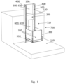
- FIG. 1 illustrates a lifting system 100 mounted on a wall 710 and comprising a drive unit 200 placed between two columns 400.
- the lifting system illustrated is a platform lifting system for transporting a person or an object from at least a first level 110 to a second level 120, wherein the platform lifting system comprises:
- Fig. 2 illustrates the lifting system 100 mounted on a wall 710, where the platform 300 compared to fig. 1 is lifted up to the second level 120.
- the drive unit can be mounted on a wall 710 of an associated building 700.
- the drive unit may also be called a "freely placeable" drive unit 200, meaning that as long the drive unit 200 is mounted between the two columns 400, it can be mounted anywhere within the area defined by the two columns 400.
- Fig. 3 illustrates the lifting system 100 mounted on a floor deck 720, and Fig. 3 further illustrates potential access openings 600.
- the lifting system is a platform lifting system for transporting a person or an object from at least a first level 110 to a second level 120.
- the lifting system 100 can comprise a plurality of access openings 600, and it should be understood, that the number of access openings 600 should not be limiting for the scope of the invention.
- potential access openings are illustrated, wherein the platform lifting system 100 has at least three access openings:
- the access openings 600 of the platform lifting system 100 illustrated in Fig. 3 should be understood only as illustrative. It would be rare that all the three sides of the platform 300 are all acting as access openings 600 at the same time and within the same lift configuration, however it is in principle possible.
- the access openings 630 of the platform 300 are illustrated as gates; however, the openings could also take other configurations than gates.
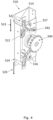
- Fig. 4 illustrates the belt drive 510.
- the belt drive comprises a frame 517. In the frame is placed the rotatable drive wheel 512 between the first set of the plurality of deflection wheels 514 and the second set of the plurality of deflection wheels 516.
- a drive shaft coupling sprocket 540 is connected to the drive unit.
- the drive unit is engaging the sprocket540, which is connected to the drive wheel 512.
- the drive unit can turn the sprocket540 both ways, so the drive wheel 512 can turn both ways and pull the toothed belt 520 both ways through the frame 517, up or down.
- the toothed belt is not shown in Fig. 4 , but can be seen in fig. 5 .
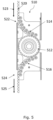
- the toothed belt enters the frame at a first opening 522 moving in the first direction, shown with the arrow 523.
- the toothed belt engages the first set of deflection wheels 514, which ensures that the toothed belt is gradually turned to engage the drive wheel 512.
- the drive wheel 512 engages with the toothed belt 520 and pulls the toothed belt through the frame 517.
- the second set of deflection wheels 516 then engages the toothed belt when it is moving away from the drive wheel 512, and the second set of deflection wheels 516 ensures the toothed belt gradually is turned to move in the second direction, shown with the arrow 525, and the toothed belts leaves the frame 517 at the second opening 524.
- the heads of the bolts 542 holding the deflection wheels is seen in fig. 4 .
- the bolts 542 is placed in fixing holes (not shown), which are placed at points on a continuous curve, preferably a circle curve.
- Fig. 5 illustrates a cross section of the frame 510, showing the drive wheel 512 placed between the first set of deflection wheels 514 and the second set of deflection wheels 516.
- the toothed belt 520 enters the frame at a first opening 522 moving in the first direction 523, and leaves the frame at the second opening 524 moving in the second direction 525.
- Fig. 6 illustrates the cross section of the frame 510, but also shows two parallel lines 550, 551.
- the parallel lines are tangents to the drive wheel 512 and are substantially parallel with the up and down moving direction of the platform 300.
- the first set of deflection wheels 514 and the second set of deflection wheels 516 are substantially located within these two parallel lines 550, 551.
- the frame in a preferred embodiment has a depth of 140 mm, a width of 70 mm and a height of 380 mm.
- the size of the frame may vary depending on the requirements.
- Fig. 7 illustrates the cross section of a column 400 with the closed end drive system 500.
- the closed end drive system 500 is a closed belt system with an endless toothed belt 520.
- the toothed belt 520 is connected at its ends to a connection element 521, preferably, a laser-cut steel tube or another kind of tube or the like.
- the platform 300 is connected to the toothed belt 520 at the connection element 521.
- the toothed belt 520 is fixed in both ends of the connection element 521, and the toothed belt is via the connection element "endless" in the sense that the ends of the toothed belt are fixed in the same tube and can therefore not move in relation to each other.
- the drive system 500 is facilitating the up and down movement of the platform 300.
- the belt drive 510 is fixed in the column 400 and is pulling the toothed belt 520 up or down through the belt drive 510.
- the belt drive then can pull the platform up by pulling down in the toothed belt 520, via a first pulley wheel 580, which the toothed belt passes over and around.
- the downward pull in the belt drive 510 is transformed to an upward pull in the platform, which causes the platform 300 to be moving up.
- a second pulley wheel 581 is placed in the lower end of the vertical column.
- the toothed belt also passes around the second pulley wheel 581 and up through the belt drive 510.
- Fig. 8a and 8b illustrates the connection between the drive unit 200 and the belt drive 510.
- the drive unit 200 preferably comprises a least:
- the drive unit further comprises:
- the belt drive 510 is connected to the driving pulley 240, by the sprocket 540, which is driving the drive wheel 512 in the belt drive 510.
- the drive wheel then drives the toothed belt 520 in the drive system 500.
- the drive unit 200 has a depth being equal or less than the depth of the two columns 400, enabling the platform 300 to pass the drive unit when moving up or down on the two columns.
Landscapes
- Engineering & Computer Science (AREA)
- Structural Engineering (AREA)
- Civil Engineering (AREA)
- Mechanical Engineering (AREA)
- Transportation (AREA)
- Automation & Control Theory (AREA)
- Power-Operated Mechanisms For Wings (AREA)
Priority Applications (4)
| Application Number | Priority Date | Filing Date | Title |
|---|---|---|---|
| EP22200578.7A EP4353646A1 (fr) | 2022-10-10 | 2022-10-10 | Système de levage de plate-forme |
| PCT/EP2023/077639 WO2024078973A1 (fr) | 2022-10-10 | 2023-10-05 | Système de levage à plate-forme |
| EP23785783.4A EP4601983A1 (fr) | 2022-10-10 | 2023-10-05 | Système de levage à plate-forme |
| US19/117,459 US12668458B2 (en) | 2022-10-10 | 2023-10-05 | Platform lifting system |
Applications Claiming Priority (1)
| Application Number | Priority Date | Filing Date | Title |
|---|---|---|---|
| EP22200578.7A EP4353646A1 (fr) | 2022-10-10 | 2022-10-10 | Système de levage de plate-forme |
Publications (1)
| Publication Number | Publication Date |
|---|---|
| EP4353646A1 true EP4353646A1 (fr) | 2024-04-17 |
Family
ID=83689878
Family Applications (2)
| Application Number | Title | Priority Date | Filing Date |
|---|---|---|---|
| EP22200578.7A Withdrawn EP4353646A1 (fr) | 2022-10-10 | 2022-10-10 | Système de levage de plate-forme |
| EP23785783.4A Pending EP4601983A1 (fr) | 2022-10-10 | 2023-10-05 | Système de levage à plate-forme |
Family Applications After (1)
| Application Number | Title | Priority Date | Filing Date |
|---|---|---|---|
| EP23785783.4A Pending EP4601983A1 (fr) | 2022-10-10 | 2023-10-05 | Système de levage à plate-forme |
Country Status (3)
| Country | Link |
|---|---|
| US (1) | US12668458B2 (fr) |
| EP (2) | EP4353646A1 (fr) |
| WO (1) | WO2024078973A1 (fr) |
Citations (3)
| Publication number | Priority date | Publication date | Assignee | Title |
|---|---|---|---|---|
| JP2009179436A (ja) * | 2008-01-30 | 2009-08-13 | Murata Mach Ltd | スタッカクレーン |
| JP2013165746A (ja) * | 2012-02-14 | 2013-08-29 | Tsutomu Sugihara | 昇降テーブル |
| CN112520285A (zh) * | 2019-09-19 | 2021-03-19 | 北京京东乾石科技有限公司 | 仓储系统 |
Family Cites Families (8)
| Publication number | Priority date | Publication date | Assignee | Title |
|---|---|---|---|---|
| GB2022936B (en) | 1978-05-17 | 1982-03-17 | Kabelschlepp Ltd | Lifting/lowering device |
| DE19758916B4 (de) | 1996-09-06 | 2011-12-08 | Bosch Rexroth Mechatronics Gmbh | Linearführungseinheit |
| JP4283917B2 (ja) * | 1998-09-08 | 2009-06-24 | 株式会社ミマキエンジニアリング | プロッタのyバーの移動機構 |
| WO2004078628A2 (fr) | 2003-03-06 | 2004-09-16 | Inventio Ag | Ascenseur |
| FI123730B (fi) * | 2006-11-10 | 2013-10-15 | Kone Corp | Järjestely hissin nopeudenrajoittimessa |
| DE102010019681B4 (de) | 2010-05-07 | 2019-10-02 | Robert Bosch Gmbh | Linearbewegungsvorrichtung mit Omega-Antrieb |
| CN113104700A (zh) * | 2021-04-30 | 2021-07-13 | 中汽昌兴(洛阳)机电设备工程有限公司 | 一种悬挂式楼房仓库升降机 |
| CN115258887B (zh) * | 2022-07-02 | 2023-07-18 | 福建力霸机械科技股份有限公司 | 安全型施工电梯 |
-
2022
- 2022-10-10 EP EP22200578.7A patent/EP4353646A1/fr not_active Withdrawn
-
2023
- 2023-10-05 EP EP23785783.4A patent/EP4601983A1/fr active Pending
- 2023-10-05 US US19/117,459 patent/US12668458B2/en active Active
- 2023-10-05 WO PCT/EP2023/077639 patent/WO2024078973A1/fr not_active Ceased
Patent Citations (3)
| Publication number | Priority date | Publication date | Assignee | Title |
|---|---|---|---|---|
| JP2009179436A (ja) * | 2008-01-30 | 2009-08-13 | Murata Mach Ltd | スタッカクレーン |
| JP2013165746A (ja) * | 2012-02-14 | 2013-08-29 | Tsutomu Sugihara | 昇降テーブル |
| CN112520285A (zh) * | 2019-09-19 | 2021-03-19 | 北京京东乾石科技有限公司 | 仓储系统 |
Also Published As
| Publication number | Publication date |
|---|---|
| WO2024078973A1 (fr) | 2024-04-18 |
| US12668458B2 (en) | 2026-06-30 |
| US20260077979A1 (en) | 2026-03-19 |
| EP4601983A1 (fr) | 2025-08-20 |
Similar Documents
| Publication | Publication Date | Title |
|---|---|---|
| CN1045939C (zh) | 附属电梯 | |
| JPH0710437A (ja) | 下部に駆動機械を備えたトラクションシーブ型エレベータ | |
| KR101766914B1 (ko) | 엘리베이터용 수직 개폐식 도어의 상부 구동축 구동시스템 | |
| CA2148423C (fr) | Espace pour mecanisme d'entrainement et ensemble de levage d'elevateur a rea de traction | |
| US6651780B1 (en) | Traction sheave elevator, hoisting unit and machine space | |
| EA014743B1 (ru) | Лифт с канатоведущим шкивом без противовеса | |
| EP0415218B1 (fr) | Positionnement d'un organe d'entraînement d'un ascenseur | |
| KR100982500B1 (ko) | 주차설비 | |
| CN1094109C (zh) | 钢索驱动的电梯 | |
| EP1195346B1 (fr) | Systeme d'ascenseur | |
| US20260077979A1 (en) | A platform lifting system | |
| RU2235670C2 (ru) | Лифт (варианты) | |
| JPH0450297Y2 (fr) | ||
| KR101998869B1 (ko) | 기계실이 없는 고하중용 엘리베이터 장치 | |
| US20250256942A1 (en) | Drive unit placement and access openings for a platform lifting system | |
| EP1967478A1 (fr) | Appareil électromécanique pour l'élévation de personnes et/ou des charges | |
| JP3800832B2 (ja) | エレベータ装置 | |
| JP2000007253A (ja) | 小形エレベータ装置 | |
| JPH053506Y2 (fr) | ||
| KR101022798B1 (ko) | 소형 기계실 설치형 승강기 | |
| KR101533557B1 (ko) | 상/하개폐식 엘리베이터의 승강장도어개폐장치 | |
| JP2859811B2 (ja) | 設備機器運搬方法及び運搬用カゴ付エレベータ | |
| KR100351276B1 (ko) | 엘리베이터의 권부각도 조절장치 | |
| JP2001080834A (ja) | エレベータ装置及びそのエレベータ制御装置の保守点検方法 | |
| CN2644392Y (zh) | 一种无机房电梯 |
Legal Events
| Date | Code | Title | Description |
|---|---|---|---|
| PUAI | Public reference made under article 153(3) epc to a published international application that has entered the european phase |
Free format text: ORIGINAL CODE: 0009012 |
|
| STAA | Information on the status of an ep patent application or granted ep patent |
Free format text: STATUS: THE APPLICATION HAS BEEN PUBLISHED |
|
| AK | Designated contracting states |
Kind code of ref document: A1 Designated state(s): AL AT BE BG CH CY CZ DE DK EE ES FI FR GB GR HR HU IE IS IT LI LT LU LV MC ME MK MT NL NO PL PT RO RS SE SI SK SM TR |
|
| STAA | Information on the status of an ep patent application or granted ep patent |
Free format text: STATUS: THE APPLICATION HAS BEEN WITHDRAWN |
|
| 18W | Application withdrawn |
Effective date: 20240426 |