EP4353666B1 - Point de butée - Google Patents
Point de butée Download PDFInfo
- Publication number
- EP4353666B1 EP4353666B1 EP23202171.7A EP23202171A EP4353666B1 EP 4353666 B1 EP4353666 B1 EP 4353666B1 EP 23202171 A EP23202171 A EP 23202171A EP 4353666 B1 EP4353666 B1 EP 4353666B1
- Authority
- EP
- European Patent Office
- Prior art keywords
- bearing
- anchor point
- closure body
- point according
- shaft section
- Prior art date
- Legal status (The legal status is an assumption and is not a legal conclusion. Google has not performed a legal analysis and makes no representation as to the accuracy of the status listed.)
- Active
Links
Images



Classifications
-
- F—MECHANICAL ENGINEERING; LIGHTING; HEATING; WEAPONS; BLASTING
- F16—ENGINEERING ELEMENTS AND UNITS; GENERAL MEASURES FOR PRODUCING AND MAINTAINING EFFECTIVE FUNCTIONING OF MACHINES OR INSTALLATIONS; THERMAL INSULATION IN GENERAL
- F16B—DEVICES FOR FASTENING OR SECURING CONSTRUCTIONAL ELEMENTS OR MACHINE PARTS TOGETHER, e.g. NAILS, BOLTS, CIRCLIPS, CLAMPS, CLIPS OR WEDGES; JOINTS OR JOINTING
- F16B45/00—Hooks; Eyes
-
- B—PERFORMING OPERATIONS; TRANSPORTING
- B66—HOISTING; LIFTING; HAULING
- B66C—CRANES; LOAD-ENGAGING ELEMENTS OR DEVICES FOR CRANES, CAPSTANS, WINCHES, OR TACKLES
- B66C1/00—Load-engaging elements or devices attached to lifting or lowering gear of cranes or adapted for connection therewith for transmitting lifting forces to articles or groups of articles
- B66C1/10—Load-engaging elements or devices attached to lifting or lowering gear of cranes or adapted for connection therewith for transmitting lifting forces to articles or groups of articles by mechanical means
- B66C1/62—Load-engaging elements or devices attached to lifting or lowering gear of cranes or adapted for connection therewith for transmitting lifting forces to articles or groups of articles by mechanical means comprising article-engaging members of a shape complementary to that of the articles to be handled
- B66C1/66—Load-engaging elements or devices attached to lifting or lowering gear of cranes or adapted for connection therewith for transmitting lifting forces to articles or groups of articles by mechanical means comprising article-engaging members of a shape complementary to that of the articles to be handled for engaging holes, recesses, or abutments on articles specially provided for facilitating handling thereof
-
- F—MECHANICAL ENGINEERING; LIGHTING; HEATING; WEAPONS; BLASTING
- F16—ENGINEERING ELEMENTS AND UNITS; GENERAL MEASURES FOR PRODUCING AND MAINTAINING EFFECTIVE FUNCTIONING OF MACHINES OR INSTALLATIONS; THERMAL INSULATION IN GENERAL
- F16B—DEVICES FOR FASTENING OR SECURING CONSTRUCTIONAL ELEMENTS OR MACHINE PARTS TOGETHER, e.g. NAILS, BOLTS, CIRCLIPS, CLAMPS, CLIPS OR WEDGES; JOINTS OR JOINTING
- F16B21/00—Means for preventing relative axial movement of a pin, spigot, shaft or the like and a member surrounding it; Stud-and-socket releasable fastenings
- F16B21/06—Releasable fastening devices with snap-action
- F16B21/07—Releasable fastening devices with snap-action in which the socket has a resilient part
- F16B21/073—Releasable fastening devices with snap-action in which the socket has a resilient part the socket having a resilient part on its inside
-
- F—MECHANICAL ENGINEERING; LIGHTING; HEATING; WEAPONS; BLASTING
- F16—ENGINEERING ELEMENTS AND UNITS; GENERAL MEASURES FOR PRODUCING AND MAINTAINING EFFECTIVE FUNCTIONING OF MACHINES OR INSTALLATIONS; THERMAL INSULATION IN GENERAL
- F16B—DEVICES FOR FASTENING OR SECURING CONSTRUCTIONAL ELEMENTS OR MACHINE PARTS TOGETHER, e.g. NAILS, BOLTS, CIRCLIPS, CLAMPS, CLIPS OR WEDGES; JOINTS OR JOINTING
- F16B35/00—Screw-bolts; Stay-bolts; Screw-threaded studs; Screws; Set screws
- F16B35/04—Screw-bolts; Stay-bolts; Screw-threaded studs; Screws; Set screws with specially-shaped head or shaft in order to fix the bolt on or in an object
- F16B35/06—Specially-shaped heads
-
- F—MECHANICAL ENGINEERING; LIGHTING; HEATING; WEAPONS; BLASTING
- F16—ENGINEERING ELEMENTS AND UNITS; GENERAL MEASURES FOR PRODUCING AND MAINTAINING EFFECTIVE FUNCTIONING OF MACHINES OR INSTALLATIONS; THERMAL INSULATION IN GENERAL
- F16B—DEVICES FOR FASTENING OR SECURING CONSTRUCTIONAL ELEMENTS OR MACHINE PARTS TOGETHER, e.g. NAILS, BOLTS, CIRCLIPS, CLAMPS, CLIPS OR WEDGES; JOINTS OR JOINTING
- F16B45/00—Hooks; Eyes
- F16B45/002—Eyes
-
- F—MECHANICAL ENGINEERING; LIGHTING; HEATING; WEAPONS; BLASTING
- F16—ENGINEERING ELEMENTS AND UNITS; GENERAL MEASURES FOR PRODUCING AND MAINTAINING EFFECTIVE FUNCTIONING OF MACHINES OR INSTALLATIONS; THERMAL INSULATION IN GENERAL
- F16G—BELTS, CABLES, OR ROPES, PREDOMINANTLY USED FOR DRIVING PURPOSES; CHAINS; FITTINGS PREDOMINANTLY USED THEREFOR
- F16G15/00—Chain couplings, Shackles; Chain joints; Chain links; Chain bushes
- F16G15/08—Swivels
Definitions
- the invention relates to an attachment point with a lower part having a connecting means for connecting the attachment point to an object to be handled therewith and with an upper part which is rotatable relative to the lower part and connected thereto and has a connecting element for connecting a lifting, attachment or lashing means, wherein for the rotatable mounting of the upper part relative to the lower part, the upper part has an upper bearing surface which tapers conically in the axial direction, the lower part has a lower bearing surface which tapers conically in the same direction and wherein, according to one embodiment, rolling bearing bodies with a shape defined by an axis of rotation and a lateral surface which is rotationally symmetrical about the axis of rotation are arranged between the two bearing surfaces, the axes of rotation of which are aligned in the direction of the conical taper of the bearing surfaces.
- Such lifting points are typically used for lifting or lashing objects.
- the lower part of the lifting points is connected to the object to be handled, whereby several lifting points are typically used to attach a corresponding lifting gear to handle such an object.
- a connecting element especially those lifting points that are not intended to be permanently attached to an object to be handled have a threaded bolt as part of the lower part, with which the lifting point is screwed into a complementary internal threaded hole in the object to be handled and is clamped to this object.
- an eyelet or a fork head can be provided as the connecting element of the upper part for connecting a lifting, lifting or lashing device.
- the connecting element can be designed so that a lifting, lifting or lashing device can be connected directly to it, or such a connecting element can have a hook eye inserted into it, to which the lifting, lifting or lashing device can then be attached.
- Lashing devices are connected.
- the anchor point remains permanently attached to an object to be handled, it is possible to weld its lower part to the object to be handled.
- the anchor point then has a corresponding welding geometry as a connecting device.
- the upper part of such an attachment point is rotatable relative to the lower part, so that when a tensile force is applied to the connecting element of the upper part, this and thus the upper part can be aligned in the direction of tension.
- the rotational mobility of the upper part relative to the lower part can be realized in different ways.
- a sliding bearing is provided between the upper and lower parts.
- Such an attachment point is made of EP 3 736 459 B1 known.
- the upper part is manually aligned before or during the application of the tensile force in the case of a transverse load, i.e., a tensile load where the tensile force does not act in the direction of the rotation axis of the upper part, in order to prevent the upper part from possibly tilting relative to the lower part due to the applied tensile force.
- a transverse load i.e., a tensile load where the tensile force does not act in the direction of the rotation axis of the upper part
- rotational mobility of the upper part relative to the lower part is sometimes no longer possible or at least impaired due to the forces acting on the bearing partners of the plain bearing. In some cases, however, rotational mobility is desired even in this situation.
- stop points have been proposed that use rolling elements instead of a plain bearing.
- DE 20 2012 100 764 U1 is such an attachment point in which two ball bearings arranged one above the other in the axial direction are provided to achieve rotational mobility.
- a similarly constructed attachment point is made of DE 201 21 118 U1 known.
- the balls used as rolling elements are also used to hold the upper and lower parts together.
- the balls used as rolling elements are each arranged in a ball channel, each of which is connected to the lower and upper parts by a A half-bore is formed that complements the ball channel.
- Each half-bore on the upper part is accessible via a mounting hole through which, after the upper part and the lower part are positioned accordingly, the balls are inserted into the respective ball channel as rolling elements.
- DE 101 64 593 B4 discloses an anchor point with increased tilt resistance against lateral tensile loads acting on the upper part.
- two deep groove ball bearings are used, with a first deep groove ball bearing arranged between the underside of the head section of the lower part and a corresponding bearing section of the upper part, while a second deep groove ball bearing with a larger diameter and thus with a greater radial distance from the axis of rotation between the upper part and the lower part is arranged between the underside of the upper part and a support disc assigned to the lower part.
- the support disc is pressed onto a cylindrical end of the anchoring screw serving as the lower part.
- EP 3 263 948 B1 A lifting point is described whose load capacity is improved compared to a lifting point with a ball-bearing upper section by using cones as rolling bearings instead of balls.
- the bearing surfaces of the upper and lower sections taper towards the connecting element of the upper section.
- EP 3 494 079 B1 discloses another stop point, the upper part of which is supported relative to the lower part by means of truncated conical rolling elements.
- the inclination direction of the rolling elements is opposite to that in EP 3 263 948 B1 described direction of inclination.
- the rolling elements also serve to hold the lower and upper parts together. that the rolling bearing bodies are inserted into the bearing channel via a mounting hole.
- EP 3 494 079 B1 In a previously known stop point, which is designed according to the preamble of claim 1, the lower part is inserted from below into a recess in the upper part.
- the diameter of the head section is therefore significantly smaller than the opening width of the upper part for inserting the lower part. For this reason, the rolling bearing bodies are inclined at only a slight angle to the rotational axis of the upper part relative to the lower part.
- the object of the invention is to propose a stop point whose upper part is mounted relative to the lower part with the interposition of non-spherical rolling elements, without the assembly problems described in the prior art, and which has lower requirements for freedom from play in its bearing surface.
- the lower part is designed to at least partially penetrate the upper part.
- the upper part therefore has a centrally arranged opening serving as a lower part receptacle, in which the lower part is arranged.
- Part of the lower part is a closure body, which is connected to the shaft section of the lower part and, on the underside, engages below the upper part in the radial direction, at least partially.
- the lower part and closure body form a common functional unit, relative to which the upper part is rotatable.
- the term “lower part” refers to that component of the functional unit “lower part” which has the head section and the shaft section.
- this part of the functional unit “lower part” can also be referred to as the screw part.
- the axial cohesion of the upper part and lower part is thus provided by the head section and the closure body of the lower part.
- the bearing surface of the lower part provided by a lateral surface section of its head section, serves to ensure axial cohesion in one direction, while the locking body engaging beneath the upper part serves to ensure cohesion in the opposite direction.
- This design allows the assembly of the stop point in which the rolling bearing bodies can be positioned in their intended spatial position on the bearing surface provided by the upper part, as well as the use of rolling bearing bodies arranged in a bearing body cage.
- the intended alignment of the non-spherical rolling bearing bodies with regard to the alignment of their axis of rotation in the direction of inclination of the bearing surfaces is ensured by such a bearing body cage.
- such a rolling bearing body serves to permanently hold the rolling bearing bodies in their intended spatial position. In this case, it is irrelevant whether the bearing has any play or not.
- This concept also allows the formation of an attachment point, where a rotational drive between the upper part and the lower part is used to clamp the lower part to an object to be handled, as in EP 3 736 459 B1 described.
- the bearing function of the rolling bearing bodies is then not impaired by the enlargement of the bearing gap caused by the coupling of the upper and lower parts.
- the rolling bearing channel which is located between the bearing surface of the upper part and that of the lower part and is open in a pre-assembly position, is closed after the rolling bearing bodies, typically held in a bearing body cage, have been placed on the bearing surface of the upper part.
- the lower part is then inserted into the central opening in the upper part, with the shaft extending through this central opening in the upper part.
- the bearing channel is then closed by the bearing surface of the lower part coming into contact with the rolling bearing bodies.
- the closing body which engages beneath the underside of the upper part, is connected to the shaft section of the lower part. This connection is made in the axial direction. This connection can, but does not have to, be torque-locked.
- the tapering direction of the bearing surfaces of the upper and lower parts and thus the angles of inclination of the axes of rotation of the rolling bearing bodies point in the direction of the closure body and in the direction of the axis of rotation of the upper part relative to the lower part.
- a locking body connected to the shaft section of the lower part has the further advantage of allowing the bearing clearance of the rotational mobility of the upper part relative to the lower part to be adjusted.
- Such a locking body is typically mounted axially onto the shaft section of the lower part, allowing the bearing clearance to be adjusted depending on the final axial position of the locking body.
- this part of the lower part can be realized, as provided in one embodiment, by a commercially available, appropriately hardened screw with a head portion whose underside is inclined toward the threaded shaft.
- Such screws typically have an angle of inclination of the underside of the head of 45° relative to the longitudinal axis.
- the mounting holes must be designed so that such rolling bodies are guided through them with their axis of rotation, and this is not necessary with the stop point according to the invention, the bearing surfaces are designed and inclined to accommodate a higher load such that the non-spherical rolling bearing bodies located therein are inclined with their axis of rotation between 30° and 60°.
- the longitudinal axes of the rolling bearing bodies enclose an angle of 45 degrees or approximately 45 degrees with the axis of rotation of the upper part.
- Such an inclination of the bearing surfaces and the rotational axes of the rolling bearing bodies is made possible by the provided closure body, which allows assembly in the axial direction, as described above.
- Another advantage of this inclination is that the opening in the upper part, through which the shaft of the lower part is to be passed, is not need not be excessively large.
- the head section of the lower part projects radially outward over the opening in the upper part, through which the shaft of the lower part passes.
- the shaft section of the lower part has a stop shoulder. This is designed with its stop surface pointing away from the head section.
- the closure body has a complementary counter-stop. With such a design, the mounting position of the closure body on the shaft section is predetermined by these two interacting stops.
- this stop point in contrast to previously known stop points with bearings provided by non-spherical rolling bearing bodies, it is not necessary for the rolling bearing bodies to be arranged without play in the bearing channel. Therefore, with this stop point, it is fundamentally not necessary to position the closure body at different axial positions on the shaft section of the lower part depending on the manufacturing tolerances of the bearing surfaces and rolling bearing bodies.
- the closure body is typically designed like a disc, with its underside facing the object to be handled, thus forming the stop surface with which the attachment point is clamped to the object to be handled.
- the advantage of such a disc-like design of the closure body is that the upper side opposite the stop surface, namely the surface of the closure body facing the underside of the upper part, can then be used as an additional bearing or support surface of the upper part relative to the lower part in the event of a transverse load.
- this preferably has a wall enclosing the shaft section of the lower part, especially if it is designed in the form of a disc.
- This wall extends in the axial direction Direction from the disc-like base body, preferably in the direction of the head section.
- the wall section formed onto the disc of the closure body is preferably used to connect the closure body to the lower part.
- the inside of this locking wall has a first locking means, while the shaft section enclosed by the locking wall carries the complementary locking means.
- This locking is designed so that the closure body can be connected to the shaft section of the lower part in a force-fitting manner, for example in a form-fitting manner, in the axial direction.
- a circumferential locking groove is introduced into the inside of the locking wall.
- the locking shaft carries a locking bead at a corresponding axial position.
- the locking bead engages in the locking groove.
- the provision of a thin locking wall integrally formed on the closure body utilizes a certain radial elasticity of the material to allow the locking bead to be pressed into the locking groove.
- the locking wall has a chamfer on the upper end of its inner side to facilitate assembly.
- the locking means described above can also be provided in a reversed position, so that the locking shaft then carries a circumferential locking groove and the locking wall carries the complementary locking bead. It is understood that a multiple arrangement is also possible, in which two or more such complementary locking means can be provided axially adjacent to one another.
- this typically cylindrical wall facing the head section of the lower part is designed as a stop surface, which is clamped to the underside of the head section.
- this free end surface of this wall acts against the bearing surface provided by the head section.
- this wall is equipped on the inside with an internal thread complementary to the thread of the threaded shaft of the lower part, which penetrates the upper part and is referred to as the screw part. Bracing is brought about by screwing the closure body onto the thread of the shaft section.
- the circumferential wall typically extends over an end section of the threaded shaft and, in a preferred embodiment, also beyond the thread run-out.
- the angles of inclination of the bearing surfaces of the upper and lower parts are the same.
- rolling bearing bodies with a cylindrical outer surface are used.
- the prevailing opinion due to the inclination of the non-spherical rolling bodies, that in such a case, truncated cone-shaped rolling bearing bodies must be used to compensate for the different travel distances during a rotational movement, has been abandoned.
- pivoting capability of only a maximum of 180° is required. Different rotational movement distances at the end sections of cylindrical rolling bearing bodies therefore do not lead to increased wear.
- the rolling bearing bodies have a barrel-shaped configuration.
- the bearing surfaces of the upper and lower parts are then adapted, at least in their central section, to the radius of curvature of these rolling bearing bodies in their longitudinal extension.
- the free rotation of the upper part relative to the lower part of this stop point can be further improved when its connecting element is subjected to a transverse load if the upper part has an additional bearing surface on its lower side facing the closure body and the closure body has a complementary bearing surface. At least when such a transverse load is applied, the upper part is supported on the bearing surface of the closure body via its bearing surface, which then interacts with the bearing surface of the closure body.
- this bearing can basically be designed as a plain bearing
- a preferred embodiment provides for rolling elements to be arranged between the lower bearing surface of the upper part and that of the closure part. These can be balls.
- this bearing provides for a needle bearing to be inserted between the relevant bearing surface of the upper part and that of the lower part.
- a needle bearing has a number of typically cylindrical bearing bodies enclosed in a bearing body cage. Such a component is easy to handle and install.
- the bearing surface of the locking body is formed by the outer side of the locking wall in the radial direction to
- the seal is limited to the inside.
- a labyrinth seal is preferably provided on the outside to prevent or minimize the ingress of contaminants into this bearing. This can be achieved, for example, by the upper part having a circumferential annular extension that radially extends beyond at least a portion of the closure body in the axial direction, subjecting a small movement gap to load.
- a locking ring is provided by which a gap between the radial outer side of the head section of the lower part and the inner side of the central opening in the upper part is closed.
- Such a locking ring can be fixed in the intended position by a locking mechanism. If the locking ring is to be connected to the lower part in a torque-locking manner, downwardly projecting locking webs can be formed on the lower part, which engage in recesses made radially on the outside in the head section and designed like grooves with open ends.
- An attachment point 1 comprises an upper part 2 and a lower part 3.
- the upper part 2 has an eyelet 4 as a connecting element for connecting a lifting, lifting or lashing device.
- the eyelet 4 is formed onto a ring-shaped base body 5.
- the ring-shaped base body 5 encloses a lower part receptacle 6 designed as an opening.
- the wall forming the inside of the base body 5 and enclosing the lower part receptacle 6 comprises an upper cylindrical wall section 7 and an adjoining bearing surface 8.
- the bearing surface 8 is conically tapered in the direction away from the eyelet 4.
- the conical taper is straight in the illustrated embodiment.
- the lower part 3 has a head section 9, a shaft section 10 and a threaded bolt 11.
- the threaded bolt 11 represents the connecting means of the anchor point 1 for connecting the anchor point 1 to an object to be handled.
- the head section 9 has a bearing surface 12 on its underside, pointing toward its threaded bolt 11. This bearing surface is tapered at the same angle and in the same direction as the bearing surface 8 of the upper part 2.
- the bearing surface 12 is provided by a lateral surface section of the head section 9, which projects radially relative to the shaft section 10.
- a hexagonal rotary driving contour 14 is incorporated into the upper end face 13 of the lower part 3, which is essentially designed as a screw bolt.
- Several rotary driving recesses 16, arranged at equal angular spacing from one another, are incorporated into the radially facing outer side 15 of the head section 9. These recesses are designed as grooves open at the ends in the axial direction.
- the shaft section 10 carries a circumferential locking bead 17.
- the bearing body cage 19 has a number of roller bearing receptacles 20 corresponding to the number of roller bearing bodies 18.
- the bearing body cage 19 has a positioning ring 21 on its upper side, the radial outer side 22 of which is supported on the wall section 7 of the upper part 2.
- a lower positioning ring 23 is shaped with respect to its outer contour in order to fit into the transition of the bearing surface 8 into a radially inwardly directed projection 24 (see Figure 3 ) to intervene.
- Part of the lower part 3 is a closure body 25 designed in the manner of a disk, which is positively connected to the shaft section 10 of the lower part 3 in the axial direction.
- the closure body 25 has a circumferential locking wall 26, on the inner side of which, facing the shaft section 10, a locking groove 27 is introduced in a complementary position to the locking bead 17.
- the locking wall 26 extends from the disk-shaped base body of the closure body 25 in the axial direction towards the head section 9 of the lower part 3.
- a needle bearing 30 is positioned on this bearing surface.
- the needle bearing 30 is only shown schematically and in an actual embodiment has more than just the four rolling elements 31 shown.
- the rolling elements 31 are held in a cage 32.
- the needle bearing 30 is easy to handle and install.
- the underside of the upper part 2 has a bearing surface facing the closure body 25, which then represents the bearing surface complementary to the bearing surface 29.
- Figure 3 in which this underside bearing surface of the upper part is identified by the reference number 33.
- a locking ring 34 serves to close an annular gap between the outer side 15 of the head section 9 of the lower part 3 and the cylindrical wall section 7 of the upper part 2.
- locking webs 35 arranged in pairs with one another are formed on the underside of the locking ring 34, the locking heads of which point away from one another.
- the locking webs 35 of a locking web pair each extend axially through a rotary drive recess 16, with their locking heads engaging behind such a rotary drive recess 16 to lock the locking ring 34 to the head portion 9 of the lower part 3.
- the locking ring 34 is torque-locked to the lower part 3.
- the locking ring 34 bears identification arrows on its upper side, which indicate the position of the rotary drive recesses 16 to a user.
- the rotary drive recesses 16 of the lower part 3 serve the purpose of allowing the anchor point 1 to be connected, by means of its upper part 2, to a handled object by hand without the need for tools.
- the upper part 2 is equipped with two independently operable coupling means 36 in the region of its annular base body 5.
- Each coupling means 36 comprises a coupling pin 37, a compression spring 38 as a return element, and an actuating cap 39, the end face of which acts against the force of the compression spring 38 when a coupling means 36 is actuated to engage the tip of the coupling pin 37 in a rotary drive recess 16.
- a reset of an actuated coupling means 36 is thus effected by the compression spring 38.
- the coupling pins 37 are each guided in a radially aligned guide bore 40 of the upper part 2.
- the actuating cap 39 is located in a recessed grip 41, which in the illustrated embodiment is designed as a funnel-shaped enlargement of the actual guide bores 40. Such a recessed grip 41 is expedient so that no actuating element protrudes beyond the outer surface of the base body 5 of the lower part 3.
- the anchor point 1 is in Figure 2 shown in its assembly and illustrates its compact design.
- the bearing of the upper part 2, which is rotatable relative to the lower part 3, is shown in the sectional view of the Figure 3 as an assembly of the Figure 1 described Individual elements are visible. Details are highlighted in the form of enlarged detailed illustrations.
- Detailed illustration A shows the cylindrical rolling bearing bodies 18 arranged in their bearing body cage 19 between the two positioning rings 21, 23. These are supported on the one hand on the bearing surface 12 as part of the head section 9 of the lower part 3.
- the complementary bearing surface of the upper part 2 is formed by the bearing surface 8. Both bearing surfaces 8, 12 are inclined at 45 degrees relative to the axis of rotation of the upper part 2 relative to the lower part 3.
- This bearing of the upper part 2 relative to the lower part 3 allows for particularly high power transmission due to the use of non-spherical rolling elements, specifically through the use of cylindrical rolling bearing bodies 18 in the illustrated embodiment. Due to the described inclination of the bearing surfaces 8, 12 and the longitudinal axis of the rolling bearing elements 18 aligned parallel to them, the upper part 2 can rotate relative to the lower part 3 under both axial and radial tensile stress. Should this bearing exhibit play or develop play due to wear, this is irrelevant for the intended use of the stop point 1. Finally, the rolling bearing elements 18 are held and guided in the rolling element cage 19, so their alignment is maintained even when bearing play is present.
- the base body 15 of the lower part 3 carries a downwardly projecting annular extension 42. This is illustrated in the enlarged detail B.
- This ring extension 42 surrounds the upper section of the disc-like closure body 25 radially on the outside and forms with this outside, leaving a movement gap a labyrinth seal 43. This prevents contaminants from penetrating the needle bearing 30 or the bearing provided by the rolling bearing bodies 18. For this purpose, a portion of the closure body 25 engages under the lower end of the annular extension 42.
- the positive connection acting in the axial direction between the closure body 25 and the shaft section 10 of the lower part 3 is shown in the detailed illustration C.
- the locking bead 27 formed on the outside of the shaft section 10 engages into the locking groove 27 of the locking wall 26.
- the shaft section 10 forms a stop shoulder 44 at the transition to its threaded bolt 11. This is engaged under by a stop extension 45 of the closure body 25.
- the runout of the thread of the threaded bolt 11 in the direction of the stop shoulder 44 is protected against transverse load stress and the associated notch effect.
- the underside of the closure body 25 is spaced from the stop shoulder 44 at which the thread of the threaded bolt 11 ends.
- the sectional view of the Figure 3 of the stop point 1 shows that the underside of the closure body 25 forms a stop surface 46 with which the stop point 1 is clamped to the surface of an object to be handled.
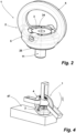
- Figure 4 shows different tensile load positions that can act on the upper part 2 or its connecting element 4, whereby the upper part 2 can still be rotated relative to the lower part 3.
- the eyelet 4 In the positions shown, the eyelet 4 is already aligned in the respective pulling direction. However, if the eyelet 4 has a different spatial position before a pulling force is applied, it will automatically align itself to the position shown in Figure 4 shown orientation. With this attachment point, loading of the connecting element of the upper part 2 is also possible in transverse directions that are inclined by more than 90 degrees with respect to an adjacent axial tensile direction. The free rotation of the upper part 2 relative to the lower part 3 under such tensile stresses is ensured by the needle bearing 30 inserted between the upper part 2 and the closure body 25 of the lower part 3.
- FIG. 5 shows another anchor point 1.1 according to the invention.
- anchor point 1 applies equally to anchor point 1.1, unless otherwise stated in the following statements.
- Identical components of anchor point 1.1 are identified by the same reference numerals as anchor point 1, but with the suffix ".1".
- the screw part is provided as part of the functional unit "lower part" by a standard screw.
- head section 9.1 has a conical surface inclined at a 45-degree angle toward the shaft section 10.1, which represents the bearing surface 12.1 on the underside of the head section 9.1.
- the shaft section 10.1 has an external thread 48, which ends axially just before the bearing surface 12.1.
- the locking body 25.1 has a complementary internal thread 49 on its inner side, which encloses the shaft section 10.1. This allows the locking body 25.1 to be screwed onto the thread 48 of the shaft 10.1.
- the closure body 25.1 also has the annular, circumferential wall 50 formed on the disc-like base body.
- the internal thread 49 also extends into this wall 50.
- the axial extent of the wall 50 is designed such that the end face facing the head section 9.1 forms a stop surface that acts against the bearing surface 12.1.
- the closure body 25.1 is clamped to the bearing surface 12.1 by the stop surface provided by the upper end of the wall 50. Additional security against loosening of the closure body 25.1 can be achieved by screwing the closure body 25.1 onto the threads of the external thread 48 that end just before the bearing surface 12.1.
- the closure body 25.1 is screwed further onto the external thread 48 of the shaft 10.1 than is possible with its own thread. This provides special protection against accidental release.
- Figure 5 The thread runout of the external thread 48 of the shaft section 10.1 is identified by the reference numeral 48.1. It is clearly visible in this figure that the wall 50, with its internal thread 49, is screwed onto the external thread 48 of the shaft section 10.1 beyond the thread runout 48.1.
- closure body 25.1 is braced with its free end face provided by the wall against the bearing surface 12.1.
- a design is also possible in which the wall is not supported on the bearing surface 12.1 of the lower part 3.1 and the position of the closure body 25.1 on the External thread 48 of shaft 10.1 is fixed by adhesive introduced into the threads.
- the bearing designed as a needle bearing 30.1 between the underside of the upper part 2.1 and the upper side of the closure body 25.1 is clearly visible in this embodiment as well.
- the cylindrical rolling bearing bodies 18.1 are also located in a rolling element cage 19. 1
- the rolling element cage 19 is 1 designed in the manner of a snap ring and sits in a circumferential groove 51 formed in the upper part 2.1.
- This groove 51 has a rectangular cross-sectional area.
- An advantage of the anchor point 1.1 is that the screw-type lower part 3.1, which together with the locking body 25.1 forms the functional unit "lower part,” is realized with a standard screw, which reduces the manufacturing costs of the anchor point 1.1. Furthermore, the locking body 25.1 can be detached from the lower part 3.1, especially multiple times.
- the anchor point 1.1 can also be connected to coupling means, as described in the embodiment of the Figures 1 to 4 described above, to ensure rotational engagement of the upper part 2.1 with the lower part 3.1. It is then only necessary to create rotational engagement recesses at appropriate locations in the radially outer surface of the head section 9.1.
- the Figure 5 described anchor point can also be designed without a roller bearing body between the two bearing surfaces of the head section and the upper part, which are inclined in the same direction and at the same angle. With such a design, it is also advisable to use the Figure 5 The bearing of the upper part relative to the lower part is then carried out via the contacting bearing surfaces as a plain bearing.
- the particularly high transverse force absorption of such a stop point is determined by the fact that the closure body with its circumferential wall extends over a threaded section of the lower part designed as a screw part, typically, as in the embodiment of the Figure 5 As described above, across the thread runout, and the transition from the cylindrical shaft section into the inclined bearing surface of the head section. Since the inclination of this bearing surface is at an angle of 45° to the longitudinal axis of the screw part, the angle between the bearing surface and the outer surface of the shaft section is 135°.
Landscapes
- Engineering & Computer Science (AREA)
- General Engineering & Computer Science (AREA)
- Mechanical Engineering (AREA)
- Rolling Contact Bearings (AREA)
- Pivots And Pivotal Connections (AREA)
- Conveying And Assembling Of Building Elements In Situ (AREA)
Claims (16)
- Point de butée comprenant une partie inférieure (3, 3.1) pourvue d'un moyen de raccordement pour relier le point de butée (1, 1.1) à un objet (47) à manipuler avec celui-ci, et une partie supérieure (2, 2.1) rotative par rapport à la partie inférieure (3, 3.1) et reliée à celle-ci et pourvue d'un élément de raccordement (4) pour relier un moyen de levage, de butée ou d'arrimage, dans lequel la partie supérieure (2, 2.1) présente, pour le montage rotatif de la partie supérieure (2) par rapport à la partie inférieure (3, 3.1), une surface d'appui supérieure (12, 12.1) se rétrécissant de manière conique dans la direction axiale, la partie inférieure (3, 3.1) présente une surface d'appui inférieure (8) se rétrécissant de manière conique dans la même direction, et dans lequel des corps de palier à roulement (18) sont disposés entre les deux surfaces d'appui (8, 12 ; 8.1, 12.1) avec une forme définie par un axe de rotation et une surface d'enveloppe symétrique en rotation autour de l'axe de rotation, les axes de rotation étant alignés dans la direction du rétrécissement conique des surfaces d'appui (8, 12 ; 8.1, 12.1), caractérisé en ce que les corps de palier à roulement (18, 18.1) avec leurs axes de rotation forment un angle supérieur ou égal à 30° et inférieur à 60° par rapport à l'axe de rotation de la partie supérieure (2, 2.1), la partie inférieure (3, 3.1) présente une section de tête (9, 9.1) et une section d'arbre (10, 10.1) formée sur celle-ci et conçue avec un petit diamètre par rapport à la section de tête (9, 9.1), dans lequel la surface d'appui (12, 12.1) de la partie inférieure (3, 3.1) est fournie par une section de surface d'enveloppe de la section de tête (9, 9.1), laquelle partie inférieure (3, 3.1) traverse la partie supérieure (2, 2.1), et en ce que pour maintenir ensemble la partie inférieure (3, 3.1) et la partie supérieure (2, 2.1), il est prévu un corps de fermeture (25, 25.1) qui est relié à la section d'arbre (10, 10.1) de la partie inférieure (3, 3.1) et vient en prise sous la partie supérieure (2, 2.1) dans la direction radiale au moins par sections.
- Point de butée selon la revendication 1, caractérisé en ce que le corps de fermeture (25, 25.1) est réalisé à la manière d'un disque dont la surface supérieure opposée à la partie inférieure (3, 3.1) forme une surface de butée (46) pour serrer le point de butée (1, 1.1) sur l'objet à manipuler (47).
- Point de butée selon l'une des revendications 1 ou 2, caractérisé en ce que la section d'arbre (10) de la partie inférieure (3) présente un épaulement de butée (44) dirigé à l'opposé de sa section de tête (9) et le corps de fermeture (25) présente une contre-butée (45) conçue de manière complémentaire à celle-ci.
- Point de butée selon l'une des revendications 1 ou 2, caractérisé en ce qu'une partie du corps de fermeture (25, 25.1) est une paroi (26, 50) qui entoure la section d'arbre (10, 10.1) de la partie inférieure (3, 3.1), s'étend dans la direction axiale de la partie inférieure (3, 3.1), ne vient pas en prise sous la partie supérieure (2, 2.1) et est équipée de moyens pour relier le corps de fermeture (25, 25.1) à la section d'arbre (10, 10.1) de la partie inférieure (3, 3.1).
- Point de butée selon la revendication 4, caractérisé en ce que la paroi formée sur le corps de fermeture (25) est réalisée sous forme de paroi de verrouillage (26) avec un côté intérieur tourné vers la section d'arbre (10) et un côté extérieur tourné dans la direction opposée, et en ce que soit la paroi de verrouillage (26) sur son côté intérieur, soit la section d'arbre (10) de la partie inférieure (3) entourée par la paroi de verrouillage, présente une rainure de verrouillage (27) ménagée dans celle-ci et, de manière complémentaire, la section d'arbre (10) entourée par la paroi de verrouillage (26) ou la paroi de verrouillage (26) sur son côté intérieur présente à un endroit complémentaire un bourrelet de verrouillage (17) venant en prise dans la rainure de verrouillage (27).
- Point de butée selon la revendication 4, caractérisé en ce que la surface frontale de la paroi (50) tournée vers la section de tête (9.1) de la partie inférieure (3.1) est conçue comme une butée qui agit contre la surface d'appui (2.1) de la partie inférieure (3.1).
- Point de butée selon la revendication 4 ou 6, caractérisé en ce que la section d'arbre (10.1) est conçue sous la forme d'une section d'arbre filetée avec un filetage extérieur (48) et le corps de fermeture (25.1) est équipé sur son côté intérieur entourant la section d'arbre (10.1) d'un filetage intérieur complémentaire (49).
- Point de butée selon l'une des revendications 1 à 7, caractérisé en ce que les corps de palier à roulement (18, 18.1) forment un angle de 45° ou d'environ 45°.
- Point de butée selon l'une des revendications 1 à 8, caractérisé en ce que les corps de palier à roulement (18, 18.1) sont disposés et guidés dans une cage de corps de palier (19, 19.1).
- Point de butée selon l'une des revendications 1 à 9, caractérisé en ce que l'angle d'inclinaison des deux surfaces d'appui (8, 12 ; 8.1, 12.1) est le même et les corps de palier à roulement (18, 18.1) présentent une surface d'enveloppe cylindrique.
- Point de butée selon l'une des revendications 1 à 10, caractérisé en ce que la partie supérieure (2, 2.1) présente sur sa face inférieure tournée vers le corps de fermeture (25, 25.1) une autre surface d'appui (33) et le corps de fermeture (25, 25.1) présente sur sa face tournée vers la partie supérieure (2, 2.1) une surface d'appui (29) coopérant avec l'autre surface d'appui (33), de sorte qu'au moins lorsque l'élément de raccordement (4) de la partie supérieure (2, 2.1) est soumis à une charge transversale, celui-ci s'appuie avec sa surface d'appui inférieure (33) sur celle du corps de fermeture (25, 25.1).
- Point de butée selon la revendication 11 en référence à l'une des revendications 4 à 6, caractérisé en ce que la surface d'appui (29) du corps de fermeture (25, 25.1) est limitée dans la direction radiale à l'intérieur par l'extérieur de la paroi (26, 50).
- Point de butée selon la revendication 11 ou 12, caractérisé en ce que des corps de roulement (31) sont disposés entre la surface d'appui inférieure (33) de la partie supérieure (2, 2.1) et celle du corps de fermeture (25, 25.1).
- Point d'arrêt selon la revendication 13, caractérisé en ce que le palier du corps de roulement est réalisé par un roulement à aiguilles (30, 30.1).
- Point de butée selon l'une des revendications 1 à 14, caractérisé en ce que la partie supérieure (2) présente une extension annulaire (34) qui entoure le corps de fermeture (25) radialement à l'extérieur dans la direction axiale sur au moins une section et qui forme avec le corps de fermeture (25) un joint labyrinthe (43).
- Point de butée selon l'une des revendications 1 à 15, caractérisé en ce que le moyen de raccordement pour relier le point de butée (1) à un objet (47) à manipuler par celui-ci est un boulon fileté (11).
Applications Claiming Priority (1)
| Application Number | Priority Date | Filing Date | Title |
|---|---|---|---|
| DE202022105768.0U DE202022105768U1 (de) | 2022-10-12 | 2022-10-12 | Anschlagpunkt |
Publications (2)
| Publication Number | Publication Date |
|---|---|
| EP4353666A1 EP4353666A1 (fr) | 2024-04-17 |
| EP4353666B1 true EP4353666B1 (fr) | 2025-04-23 |
Family
ID=88295663
Family Applications (1)
| Application Number | Title | Priority Date | Filing Date |
|---|---|---|---|
| EP23202171.7A Active EP4353666B1 (fr) | 2022-10-12 | 2023-10-06 | Point de butée |
Country Status (6)
| Country | Link |
|---|---|
| US (1) | US20240124270A1 (fr) |
| EP (1) | EP4353666B1 (fr) |
| CN (1) | CN117869449A (fr) |
| DE (1) | DE202022105768U1 (fr) |
| PL (1) | PL4353666T3 (fr) |
| TW (1) | TW202426386A (fr) |
Families Citing this family (1)
| Publication number | Priority date | Publication date | Assignee | Title |
|---|---|---|---|---|
| DE102019135324A1 (de) * | 2019-12-19 | 2021-06-24 | Pewag Austria Gmbh | Anschlussvorrichtung zum Ankoppeln einer Last an eine Tragöse mittels eines Tragbolzens |
Family Cites Families (7)
| Publication number | Priority date | Publication date | Assignee | Title |
|---|---|---|---|---|
| US2487085A (en) * | 1946-04-18 | 1949-11-08 | Wridge Virgil | Swivel arch hook |
| DE10164593B4 (de) | 2001-12-21 | 2006-01-12 | Rud-Kettenfabrik Rieger & Dietz Gmbh U. Co. | Anschlagpunkt |
| DE20121118U1 (de) | 2001-12-21 | 2002-05-02 | RUD-Kettenfabrik Rieger & Dietz GmbH u. Co., 73432 Aalen | Anschlagmittel |
| DE202012100764U1 (de) | 2012-03-05 | 2012-04-27 | Thiele Gmbh & Co. Kg | Ringschraube |
| DE202016004078U1 (de) | 2016-06-28 | 2016-08-26 | Manfred Redder | Anschlagwirbel bei dem das gegenüber dem Unterteil drehbare Oberteil durch einen in eine Lagerbohrung eingreifenden Lagerzapfen und Lagerrollen formschlüssig miteinander verbunden sind |
| DE202016006871U1 (de) | 2016-11-04 | 2016-12-05 | Manfred Redder | Anschlagring mit einer zum Einhängen eines Anschlagmittels oder Zurrmittels dienenden Tragöse. |
| DE202019102552U1 (de) | 2019-05-07 | 2019-05-27 | J. D. Theile Gmbh & Co. Kg | Anschlagpunkt |
-
2022
- 2022-10-12 DE DE202022105768.0U patent/DE202022105768U1/de active Active
-
2023
- 2023-09-07 TW TW112134029A patent/TW202426386A/zh unknown
- 2023-10-06 EP EP23202171.7A patent/EP4353666B1/fr active Active
- 2023-10-06 PL PL23202171.7T patent/PL4353666T3/pl unknown
- 2023-10-11 US US18/484,698 patent/US20240124270A1/en active Pending
- 2023-10-11 CN CN202311329069.4A patent/CN117869449A/zh active Pending
Also Published As
| Publication number | Publication date |
|---|---|
| CN117869449A (zh) | 2024-04-12 |
| TW202426386A (zh) | 2024-07-01 |
| EP4353666A1 (fr) | 2024-04-17 |
| PL4353666T3 (pl) | 2025-07-14 |
| DE202022105768U1 (de) | 2024-01-15 |
| US20240124270A1 (en) | 2024-04-18 |
Similar Documents
| Publication | Publication Date | Title |
|---|---|---|
| DE60021730T2 (de) | Hochfester Blindbolzen über einen erweiterten Greifbereich gleichmäßig hoher Klemmkraft | |
| DE2813025C2 (de) | Sicherheitsbolzen | |
| DE102010038067A1 (de) | Formschlussverbindung mit Ausgleich von Lagefehlern | |
| EP0002654A1 (fr) | Dispositif de fixation avec une cheville verrouillée par clavetage dans une partie d'un trou présentant un plus grand diamètre | |
| DE3309884C2 (fr) | ||
| DE10222107B3 (de) | Schrauben-Muttern-Anordnung mit integrierter, sofort wirkender Sicherung gegen unbeabsichtigtes Lösen einer damit gebildeten Schraubverbindung | |
| DE102020101057B3 (de) | Aufbau eines Drehmomentschlüssels | |
| WO2018127336A1 (fr) | Dispositif de régulation de couple à trois organes de liaison | |
| DE2700605A1 (de) | Drehsicherung fuer eine gewindeverbindung | |
| EP2569550B1 (fr) | Moyen de fixation autobloquant et système de fixation | |
| EP0275441B1 (fr) | Dispositif de serrage | |
| EP4353666B1 (fr) | Point de butée | |
| DE19834582B4 (de) | Drehmomentbegrenzende Kupplung | |
| DE9211729U1 (de) | Knarre für Steckschlüsseleinsätze und Schraubendreher | |
| DE29816410U1 (de) | Gewindespindelantrieb für ein Federspanngerät | |
| EP3909903B1 (fr) | Point de butée | |
| DE102017107583B4 (de) | Rolle | |
| EP0310775B1 (fr) | Dispositif de fermeture pour relier des pièces de construction en forme de plaques | |
| DE102008005454A1 (de) | Scheibenbremse mit Rutschkupplung für die Nachstelleinrichtung | |
| EP1837108A1 (fr) | Mandrin à diaphragme | |
| DE19829251A1 (de) | Bohrvorrichtung | |
| EP4353665B1 (fr) | Point de butée | |
| DE20306065U1 (de) | Walzenförmiger Schneidkörper | |
| DE4015473A1 (de) | Anhaengerkupplung, stichwort: verliersicherung mit wackelabstand | |
| DE29912708U1 (de) | Schraubwerkzeug zum Eindrehen von Gewindebolzen |
Legal Events
| Date | Code | Title | Description |
|---|---|---|---|
| PUAI | Public reference made under article 153(3) epc to a published international application that has entered the european phase |
Free format text: ORIGINAL CODE: 0009012 |
|
| STAA | Information on the status of an ep patent application or granted ep patent |
Free format text: STATUS: THE APPLICATION HAS BEEN PUBLISHED |
|
| AK | Designated contracting states |
Kind code of ref document: A1 Designated state(s): AL AT BE BG CH CY CZ DE DK EE ES FI FR GB GR HR HU IE IS IT LI LT LU LV MC ME MK MT NL NO PL PT RO RS SE SI SK SM TR |
|
| P01 | Opt-out of the competence of the unified patent court (upc) registered |
Effective date: 20240426 |
|
| STAA | Information on the status of an ep patent application or granted ep patent |
Free format text: STATUS: REQUEST FOR EXAMINATION WAS MADE |
|
| 17P | Request for examination filed |
Effective date: 20240925 |
|
| RBV | Designated contracting states (corrected) |
Designated state(s): AL AT BE BG CH CY CZ DE DK EE ES FI FR GB GR HR HU IE IS IT LI LT LU LV MC ME MK MT NL NO PL PT RO RS SE SI SK SM TR |
|
| GRAP | Despatch of communication of intention to grant a patent |
Free format text: ORIGINAL CODE: EPIDOSNIGR1 |
|
| STAA | Information on the status of an ep patent application or granted ep patent |
Free format text: STATUS: GRANT OF PATENT IS INTENDED |
|
| INTG | Intention to grant announced |
Effective date: 20250127 |
|
| RAP3 | Party data changed (applicant data changed or rights of an application transferred) |
Owner name: J.D. THEILE GMBH & CO. KG |
|
| GRAS | Grant fee paid |
Free format text: ORIGINAL CODE: EPIDOSNIGR3 |
|
| GRAA | (expected) grant |
Free format text: ORIGINAL CODE: 0009210 |
|
| STAA | Information on the status of an ep patent application or granted ep patent |
Free format text: STATUS: THE PATENT HAS BEEN GRANTED |
|
| AK | Designated contracting states |
Kind code of ref document: B1 Designated state(s): AL AT BE BG CH CY CZ DE DK EE ES FI FR GB GR HR HU IE IS IT LI LT LU LV MC ME MK MT NL NO PL PT RO RS SE SI SK SM TR |
|
| REG | Reference to a national code |
Ref country code: GB Ref legal event code: FG4D Free format text: NOT ENGLISH |
|
| REG | Reference to a national code |
Ref country code: CH Ref legal event code: EP |
|
| REG | Reference to a national code |
Ref country code: DE Ref legal event code: R096 Ref document number: 502023000866 Country of ref document: DE |
|
| REG | Reference to a national code |
Ref country code: IE Ref legal event code: FG4D Free format text: LANGUAGE OF EP DOCUMENT: GERMAN |
|
| REG | Reference to a national code |
Ref country code: SE Ref legal event code: TRGR |
|
| REG | Reference to a national code |
Ref country code: NL Ref legal event code: FP |
|
| PG25 | Lapsed in a contracting state [announced via postgrant information from national office to epo] |
Ref country code: FI Free format text: LAPSE BECAUSE OF FAILURE TO SUBMIT A TRANSLATION OF THE DESCRIPTION OR TO PAY THE FEE WITHIN THE PRESCRIBED TIME-LIMIT Effective date: 20250423 Ref country code: PT Free format text: LAPSE BECAUSE OF FAILURE TO SUBMIT A TRANSLATION OF THE DESCRIPTION OR TO PAY THE FEE WITHIN THE PRESCRIBED TIME-LIMIT Effective date: 20250825 Ref country code: ES Free format text: LAPSE BECAUSE OF FAILURE TO SUBMIT A TRANSLATION OF THE DESCRIPTION OR TO PAY THE FEE WITHIN THE PRESCRIBED TIME-LIMIT Effective date: 20250423 |
|
| REG | Reference to a national code |
Ref country code: LT Ref legal event code: MG9D |
|
| PG25 | Lapsed in a contracting state [announced via postgrant information from national office to epo] |
Ref country code: NO Free format text: LAPSE BECAUSE OF FAILURE TO SUBMIT A TRANSLATION OF THE DESCRIPTION OR TO PAY THE FEE WITHIN THE PRESCRIBED TIME-LIMIT Effective date: 20250723 Ref country code: GR Free format text: LAPSE BECAUSE OF FAILURE TO SUBMIT A TRANSLATION OF THE DESCRIPTION OR TO PAY THE FEE WITHIN THE PRESCRIBED TIME-LIMIT Effective date: 20250724 |
|
| PGFP | Annual fee paid to national office [announced via postgrant information from national office to epo] |
Ref country code: TR Payment date: 20250929 Year of fee payment: 3 Ref country code: PL Payment date: 20250915 Year of fee payment: 3 |
|
| PG25 | Lapsed in a contracting state [announced via postgrant information from national office to epo] |
Ref country code: BG Free format text: LAPSE BECAUSE OF FAILURE TO SUBMIT A TRANSLATION OF THE DESCRIPTION OR TO PAY THE FEE WITHIN THE PRESCRIBED TIME-LIMIT Effective date: 20250423 |
|
| PG25 | Lapsed in a contracting state [announced via postgrant information from national office to epo] |
Ref country code: HR Free format text: LAPSE BECAUSE OF FAILURE TO SUBMIT A TRANSLATION OF THE DESCRIPTION OR TO PAY THE FEE WITHIN THE PRESCRIBED TIME-LIMIT Effective date: 20250423 |
|
| PG25 | Lapsed in a contracting state [announced via postgrant information from national office to epo] |
Ref country code: RS Free format text: LAPSE BECAUSE OF FAILURE TO SUBMIT A TRANSLATION OF THE DESCRIPTION OR TO PAY THE FEE WITHIN THE PRESCRIBED TIME-LIMIT Effective date: 20250723 |
|
| PGFP | Annual fee paid to national office [announced via postgrant information from national office to epo] |
Ref country code: CZ Payment date: 20250923 Year of fee payment: 3 |
|
| PG25 | Lapsed in a contracting state [announced via postgrant information from national office to epo] |
Ref country code: IS Free format text: LAPSE BECAUSE OF FAILURE TO SUBMIT A TRANSLATION OF THE DESCRIPTION OR TO PAY THE FEE WITHIN THE PRESCRIBED TIME-LIMIT Effective date: 20250823 |
|
| PG25 | Lapsed in a contracting state [announced via postgrant information from national office to epo] |
Ref country code: LV Free format text: LAPSE BECAUSE OF FAILURE TO SUBMIT A TRANSLATION OF THE DESCRIPTION OR TO PAY THE FEE WITHIN THE PRESCRIBED TIME-LIMIT Effective date: 20250423 |
|
| PGFP | Annual fee paid to national office [announced via postgrant information from national office to epo] |
Ref country code: LU Payment date: 20251022 Year of fee payment: 3 |
|
| PGFP | Annual fee paid to national office [announced via postgrant information from national office to epo] |
Ref country code: DE Payment date: 20250902 Year of fee payment: 3 |
|
| PG25 | Lapsed in a contracting state [announced via postgrant information from national office to epo] |
Ref country code: DK Free format text: LAPSE BECAUSE OF FAILURE TO SUBMIT A TRANSLATION OF THE DESCRIPTION OR TO PAY THE FEE WITHIN THE PRESCRIBED TIME-LIMIT Effective date: 20250423 Ref country code: SM Free format text: LAPSE BECAUSE OF FAILURE TO SUBMIT A TRANSLATION OF THE DESCRIPTION OR TO PAY THE FEE WITHIN THE PRESCRIBED TIME-LIMIT Effective date: 20250423 |
|
| PGFP | Annual fee paid to national office [announced via postgrant information from national office to epo] |
Ref country code: AT Payment date: 20260113 Year of fee payment: 3 |
|
| PGFP | Annual fee paid to national office [announced via postgrant information from national office to epo] |
Ref country code: IT Payment date: 20251031 Year of fee payment: 3 |
|
| PGFP | Annual fee paid to national office [announced via postgrant information from national office to epo] |
Ref country code: FR Payment date: 20251024 Year of fee payment: 3 |
|
| PG25 | Lapsed in a contracting state [announced via postgrant information from national office to epo] |
Ref country code: EE Free format text: LAPSE BECAUSE OF FAILURE TO SUBMIT A TRANSLATION OF THE DESCRIPTION OR TO PAY THE FEE WITHIN THE PRESCRIBED TIME-LIMIT Effective date: 20250423 |
|
| REG | Reference to a national code |
Ref country code: DE Ref legal event code: R097 Ref document number: 502023000866 Country of ref document: DE |
|
| PG25 | Lapsed in a contracting state [announced via postgrant information from national office to epo] |
Ref country code: SK Free format text: LAPSE BECAUSE OF FAILURE TO SUBMIT A TRANSLATION OF THE DESCRIPTION OR TO PAY THE FEE WITHIN THE PRESCRIBED TIME-LIMIT Effective date: 20250423 |
|
| PLBE | No opposition filed within time limit |
Free format text: ORIGINAL CODE: 0009261 |
|
| STAA | Information on the status of an ep patent application or granted ep patent |
Free format text: STATUS: NO OPPOSITION FILED WITHIN TIME LIMIT |
|
| REG | Reference to a national code |
Ref country code: CH Ref legal event code: L10 Free format text: ST27 STATUS EVENT CODE: U-0-0-L10-L00 (AS PROVIDED BY THE NATIONAL OFFICE) Effective date: 20260304 |
|
| PG25 | Lapsed in a contracting state [announced via postgrant information from national office to epo] |
Ref country code: RO Free format text: LAPSE BECAUSE OF FAILURE TO SUBMIT A TRANSLATION OF THE DESCRIPTION OR TO PAY THE FEE WITHIN THE PRESCRIBED TIME-LIMIT Effective date: 20250423 |
|
| 26N | No opposition filed |
Effective date: 20260126 |