EP4354010A1 - Dispositif de surveillance - Google Patents
Dispositif de surveillance Download PDFInfo
- Publication number
- EP4354010A1 EP4354010A1 EP23184039.8A EP23184039A EP4354010A1 EP 4354010 A1 EP4354010 A1 EP 4354010A1 EP 23184039 A EP23184039 A EP 23184039A EP 4354010 A1 EP4354010 A1 EP 4354010A1
- Authority
- EP
- European Patent Office
- Prior art keywords
- sensor
- monitoring device
- safety
- safety sensor
- protective field
- Prior art date
- Legal status (The legal status is an assumption and is not a legal conclusion. Google has not performed a legal analysis and makes no representation as to the accuracy of the status listed.)
- Granted
Links
Images


Classifications
-
- F—MECHANICAL ENGINEERING; LIGHTING; HEATING; WEAPONS; BLASTING
- F16—ENGINEERING ELEMENTS AND UNITS; GENERAL MEASURES FOR PRODUCING AND MAINTAINING EFFECTIVE FUNCTIONING OF MACHINES OR INSTALLATIONS; THERMAL INSULATION IN GENERAL
- F16P—SAFETY DEVICES IN GENERAL; SAFETY DEVICES FOR PRESSES
- F16P3/00—Safety devices acting in conjunction with the control or operation of a machine; Control arrangements requiring the simultaneous use of two or more parts of the body
- F16P3/12—Safety devices acting in conjunction with the control or operation of a machine; Control arrangements requiring the simultaneous use of two or more parts of the body with means, e.g. feelers, which in case of the presence of a body part of a person in or near the danger zone influence the control or operation of the machine
- F16P3/14—Safety devices acting in conjunction with the control or operation of a machine; Control arrangements requiring the simultaneous use of two or more parts of the body with means, e.g. feelers, which in case of the presence of a body part of a person in or near the danger zone influence the control or operation of the machine the means being photocells or other devices sensitive without mechanical contact
- F16P3/144—Safety devices acting in conjunction with the control or operation of a machine; Control arrangements requiring the simultaneous use of two or more parts of the body with means, e.g. feelers, which in case of the presence of a body part of a person in or near the danger zone influence the control or operation of the machine the means being photocells or other devices sensitive without mechanical contact using light grids
-
- F—MECHANICAL ENGINEERING; LIGHTING; HEATING; WEAPONS; BLASTING
- F16—ENGINEERING ELEMENTS AND UNITS; GENERAL MEASURES FOR PRODUCING AND MAINTAINING EFFECTIVE FUNCTIONING OF MACHINES OR INSTALLATIONS; THERMAL INSULATION IN GENERAL
- F16P—SAFETY DEVICES IN GENERAL; SAFETY DEVICES FOR PRESSES
- F16P3/00—Safety devices acting in conjunction with the control or operation of a machine; Control arrangements requiring the simultaneous use of two or more parts of the body
- F16P3/12—Safety devices acting in conjunction with the control or operation of a machine; Control arrangements requiring the simultaneous use of two or more parts of the body with means, e.g. feelers, which in case of the presence of a body part of a person in or near the danger zone influence the control or operation of the machine
- F16P3/14—Safety devices acting in conjunction with the control or operation of a machine; Control arrangements requiring the simultaneous use of two or more parts of the body with means, e.g. feelers, which in case of the presence of a body part of a person in or near the danger zone influence the control or operation of the machine the means being photocells or other devices sensitive without mechanical contact
- F16P3/142—Safety devices acting in conjunction with the control or operation of a machine; Control arrangements requiring the simultaneous use of two or more parts of the body with means, e.g. feelers, which in case of the presence of a body part of a person in or near the danger zone influence the control or operation of the machine the means being photocells or other devices sensitive without mechanical contact using image capturing devices
-
- G—PHYSICS
- G01—MEASURING; TESTING
- G01V—GEOPHYSICS; GRAVITATIONAL MEASUREMENTS; DETECTING MASSES OR OBJECTS; TAGS
- G01V8/00—Prospecting or detecting by optical means
- G01V8/10—Detecting, e.g. by using light barriers
- G01V8/20—Detecting, e.g. by using light barriers using multiple transmitters or receivers
Definitions
- the invention relates to a monitoring device
- Such a monitoring device comprises a safety sensor by means of which objects within a protective field are detected.
- Such monitoring devices are generally used in the field of security technology, particularly in the field of personal protection.
- the safety sensor is typically used to monitor access to a danger area on a system.
- a safety sensor in the form of a light grid used for such monitoring tasks is known from the DE 299 20 715 U1 known.
- the light grid comprises a multiple arrangement of light barriers. If an object or a person is detected with this light grid, an object message is generated in the light grid, which leads to the shutdown of a machine or system.
- the light grid thus fulfils its safety function, since it detects when a person enters the danger zone, which would endanger the person if the machine or system remained switched on. However, if a workpiece to be processed with the machine or system entered the danger zone, this would also lead to an object message in the light grid, which would then result in the machine being switched off. Since the workpiece to be processed is not a safety-critical object, switching off the machine or system when it is detected within the danger zone is unnecessary and therefore undesirable.
- the light grid of the DE 299 20 715 Ul In addition to the light barrier arrangement at the entrance or exit of the danger zone, so-called muting sensors are provided which enable a distinction to be made between people or generally safety-critical objects and permissible objects as non-safety-critical objects. If a permissible object is detected, the muting sensors generate a muting signal, i.e. a bridging signal which means that despite an interruption of the light barriers of the light grid, the shutdown function is temporarily deactivated, i.e. the machine or system is not switched off. If, however, one of the light barriers is interrupted and the muting sensors do not generate a bridging signal, the machine or system to be monitored is switched off.
- a muting signal i.e. a bridging signal
- a safety sensor which is used to monitor the danger area of a machine or system, comprising a sensor unit with at least one transmitter emitting light beams and a receiver receiving light beams for monitoring a protective field, as well as an evaluation unit in which a shutdown command for the machine or system is generated as a safety function when an object is detected in the protective field.
- a sensor unit with at least one transmitter emitting light beams and a receiver receiving light beams for monitoring a protective field
- an evaluation unit in which a shutdown command for the machine or system is generated as a safety function when an object is detected in the protective field.
- a safe bridging signal bridging the safety function of the safety sensor is only generated if an object presence signal is registered by each of the signal sources within a time interval determined by the requirements of the relevant safety standards.
- the safety sensor is transferred to a safe locking state by the bridging unit if the second object presence signal is not registered in the bridging unit after the first object presence signal has been registered within the time interval.
- the invention is based on the object of providing a monitoring device with an extended functionality.
- the invention comprises a monitoring device with a safety sensor, by means of which objects within a protective field can be detected.
- the safety sensor triggers a safety function when it registers an object intrusion in the protective field.
- a bridging unit and detection means by means of which an object moving towards the safety sensor can be detected in succession at least at two detection points, are present.
- At least one area of the protective field of the safety sensor is only bridged with the bridging unit if an object intrusion is registered at the detection points within a predetermined time interval, whereby if an object intrusion occurs in the bridged area of the protective field, the safety sensor does not trigger a safety function.
- the monitoring device according to the invention is suitable for use in safety-related applications.
- the protective field is used to monitor access to a hazardous area of a system.
- the safety sensor performs a monitoring function in such a way that in normal operation the safety sensor triggers a safety function when it registers an object intrusion in the protective field.
- the safety function can advantageously consist in the fact that the safety function shuts down a system monitored by safety sensors.
- the term plant generally also includes machines or other work equipment.
- the monitoring device has a bridging unit with which a gating function, i.e. a bridging function, is realized.
- At least a partial area of the protective field is temporarily bridged so that objects can pass through the protective field without the safety sensor triggering the safety function and thus shutting down the system.
- the gating function is carried out with a bridging unit, whereby the bridging unit evaluates signals from detection means that detect objects moving towards the safety sensor at at least two detection points.
- the detection points are advantageously arranged one behind the other at a distance in the direction of movement of objects moving towards the safety sensor.
- the detection points are selected so that an object moving towards the safety sensor is detected sequentially by the detection means at the detection points.
- the bridging unit monitors simultaneity in such a way that a gating function in the form of bridging at least one area of the protective field of the safety sensor is only triggered if an object intervention is registered at both detection points within a predetermined time interval.
- a gating function in the form of bridging at least one area of the protective field of the safety sensor is only triggered if an object intervention is registered at both detection points within a predetermined time interval.
- the distance between the detection points and the safety sensor, as well as the size of the time interval, are selected so that the gating function is only triggered when a non-hazardous object, such as a transport item, passes the detection point.
- the detection device is used to differentiate between permissible objects and impermissible objects, i.e. object classification is possible based on the signals from the detection device.
- Permissible objects are made up of non-hazardous objects, such as transported goods.
- Impermissible objects can be people in particular.
- sensor means are provided as detection means, by means of which object interventions can be detected at both detection points.
- one sensor is sufficient to detect objects at both detection points.
- the second detection point assigned to the safety sensor is advantageously located at a distance from the safety sensor that is smaller than a specified minimum distance. This ensures that the object that passes the safety sensor is the object that was previously detected by the sensor means at the two detection points.
- sensor means are provided as the first detection means, by means of which object interventions can be detected at a first detection point.
- the safety sensor forms a second detection means, by means of which object interventions can be detected at a second detection point, namely the location of the safety sensor.
- the second detection point coincides with the position of the safety sensor. This means that a permissible object is detected immediately when it is placed in the protective field.
- the bridging unit transfers the safety sensor into a safe locking state if, after an object intervention at a first detection point, no object intervention is registered at the second detection point within the predetermined time interval.
- a system monitored by the safety sensor is immediately transferred to a safe state, preferably shut down.
- the detection devices differ from known muting sensors such as light barriers or signal sources such as those from the EN 10 2009 048 111 B4 are known.
- the sensor means can be formed by a radar system.
- the sensor means can be formed by an arrangement of induction loops.
- the sensor means are formed by position sensors of a vehicle.
- the vehicle can, for example, be formed by an AGV (driverless transport system), where a navigation system can be provided as a recording device.
- AGV driverless transport system
- a navigation system can be provided as a recording device.
- the sensor means do not generate fail-safe signals.
- the fail-safe nature of the monitoring device required for use in safety technology is achieved on the one hand by the fact that the safety sensor has a fail-safe design.
- the fault tolerance of the monitoring device is achieved by the fact that the bridging unit has a fail-safe design.
- the bridging unit is formed by the evaluation unit of the safety sensor.
- the fail-safe bridging unit and the simultaneous monitoring of the signals from the detection devices that are generated when monitoring the detection point ensure the necessary fail-safe nature of the monitoring device.
- the safety sensor is a light curtain, an area distance sensor or a camera sensor.
- the safety sensor is used to monitor a flat or spatial protective field.
- the monitoring unit In general, it is possible to use the monitoring unit to bridge not only a part of the protective field, but the entire protective field.
- bridging unit it is also possible to use the bridging unit to bridge several sub-areas of the protective field of the safety sensor.
- the bridging of the safety sensor is maintained for a predetermined period of time.
- This time period is adapted to the speed of a permissible object so that the bridging is maintained for the time it takes the permissible object to pass the safety sensor.
- Another advantage is that the bridging can be terminated if the safety switch does not detect any object in the protective field.
- Figure 1 shows a first embodiment of a safety sensor in the form of a light curtain 1, by means of which a flat protective field 2 is monitored.
- the light curtain 1 comprises an arrangement of transmitters 4 emitting light beams 3, which are cyclically activated one after the other by a control unit (not shown).
- the transmitters 4 and the control unit are integrated in a transmitter unit 5 with a first housing.
- the light curtain 1 further comprises an arrangement of receivers 6 for receiving the light beams 3.
- the receivers 6 are integrated in a receiver unit 7 with a second housing.
- the transmitters 4 are controlled by a transmitter control 8.
- the receivers 6 are assigned an evaluation unit 9 for controlling the receiver operation and for evaluating the received signals present at the outputs of the receivers 6.
- the evaluation unit 9 has a redundant structure.
- the evaluation unit 9 preferably consists of two cyclically monitoring computer units.
- the light curtain 1 monitors a protective field 2, which is defined by the area between the two housings.
- Each transmitter 4 is assigned a receiver 6 so that when the protective field 2 is free, the light beams 3 emitted by the transmitter 4 hit the receiver 6.
- Each transmitter 4 and the assigned receiver 6 define a beam axis of the light curtain 1, the direction of the beam axis being given by the light beams 3 of the respective transmitter 4.
- a fail-safe switching signal is generated depending on the signals from the sensor unit, the switching states of which indicate whether an object is in the protective field 2 or not.
- the switching signal is output via a safety switching output 10, which is advantageously designed with multiple channels.
- the safety switching output 10 is switched on according to the current switching state of the switching signal. If an object enters the protective field 2, the safety switching output 10 is switched off.
- Figure 2 shows an embodiment of a safety sensor in the form of an area distance sensor.
- the area distance sensor has a distance sensor that operates according to a pulse transit time method with a transmitting element 12 that emits transmitted light beams 11 and a receiving element 14 that receives received light beams 13, whereby the distance of the target object 15 is determined from the light transit time to a target object 15 and back to the area distance sensor.
- the transmitting element 12 and the receiving element 14 are mounted by means of a holder in a measuring head 16, the outer surface of which forms an exit window for the transmitted light beams 11 and received light beams 13.
- the measuring head 16 is rotatably mounted on a base 17. By means of a drive (not shown), the measuring head 16 is set in a rotary movement about a rotation axis D. whereby the transmitted light beams 11 periodically sweep over a flat protective field 2.
- the area distance sensor can be designed such that the transmitting element 12 and receiving element 14 are arranged stationary in a housing.
- the transmitted light beams 11 are then periodically deflected by a motor-driven deflection unit.
- Figure 3 shows an embodiment of a security sensor in the form of a camera sensor, which has an image sensor 18 and an illumination unit 19.
- the image sensor 18 can have a linear or matrix arrangement of pixels.
- the image sensor 18 can be formed by a CCD or CMOS array.
- the safety sensors also comply with the Figures 2 and 3 an evaluation unit 9 and a safety switching output 10.
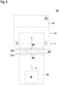
- FIG 4 shows a first embodiment of the monitoring device 20 according to the invention with a safety sensor in the form of a light curtain 1.
- a safety sensor in the form of a light curtain 1.
- an area distance sensor or camera sensor can also be used. This also applies to the embodiments of Figures 5 and 6.
- the light curtain 1 monitors access to a danger zone 21 of a system 22.
- the system 22 is controlled by a system control 23.
- the safety switching output 10 of the light curtain 1 is connected to the system control 23.
- the light curtain 1 In normal operation of the light curtain 1, it monitors the entire protective field 2. When the protective field 2 is free, the light curtain 1 generates a corresponding switching signal, which switches on the safety switching output 10. is released, whereby the operation of the system 22 is enabled. If an object enters the protective field 2, the light curtain 1 generates a switching signal, which switches off the safety switching output 10. This triggers a safety function in such a way that the system 22 is shut down.
- a bridging unit 24 is provided, by means of which the protective field 2 of the light curtain 1 is temporarily at least partially bridged.
- the bridging unit 24 forms a fail-safe unit that preferably has two mutually monitoring computer units. In the present case, the bridging unit 24 forms a separate unit. Alternatively, the bridging unit 24 can be integrated in the evaluation unit 9 of the light curtain 1.
- a transport item 25 is moved as a permissible object on a conveyor line 26 in a transport device T in the direction of the safety sensor in order to feed the transport item 25 to the system 22.
- Induction loops 28a, 28b are provided on the conveyor line 26 at two detection points 27a, 27b, which extend over the entire width of the conveyor line 26.
- the detection points 27a, 27b with the induction loops 28a, 28b are arranged one behind the other in the transport direction T.
- the induction loops 28a, 28b form non-fail-safe sensor means for detecting the transported goods 25 and are connected to the bridging unit 24.
- the distances between the first detection point 27a and the second detection point 27b and to the light curtain 1 are adjusted accordingly.
- the induction loops 28a, 28b only metallic bodies, such as the surface of the transported goods 25, are detected. This also makes it possible to distinguish between permissible and impermissible objects.
- the transported goods 25 approaching the safety sensor are detected in that the first induction loop 28a initially registers an object intervention by the transported goods 25 and then, within a time interval predetermined in the bridging unit 24, which is e.g. 4 seconds, the second induction loop 28b also registers an object intervention.
- At least a partial area of the protective field 2 of the light curtain 1 is bridged by a command from the bridging unit 24, so that an object intervention there does not trigger the safety function.
- the bridged partial area is adapted to the dimensions of the transported goods 25, so that the transported goods 25 can pass through the protective field 2 without the safety function being triggered.
- the bridging of the safety sensor is maintained for a predetermined period of time.
- the time duration is adapted to the time required for the transport item 25 to pass through the protective field 2.
- the bridging is terminated if no object is detected in protective field 2 by the safety switch.
- the bridging unit 24 transfers the safety sensor into a safe locking state if, after an object intervention at a first detection point 27a, no object intervention is registered at the second detection point 27b within the predetermined time interval.
- the safe locking state is realized by switching off the safety switching output 10 of the light curtain 1, whereby the system 22 is immediately shut down.
- the embodiment of the Figure 4 can be modified in such a way that only one induction loop 28b is provided as a sensor means. Then the light curtain 1 forms a further detection means in addition to the induction loop 28b, by means of which a transport item 25 or generally a permissible object is considered to be detected if an object intervention is first registered in the induction loop 28b and then an object intervention is registered with the light curtain 1 within the specified time interval. Only if this condition is met will the light curtain 1 be bypassed.
- the light curtain 1 is transferred to the safe locking state.
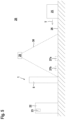
- FIG. 5 shows a variant of the embodiment according to Figure 4 Instead of induction loops 28a, 28b, a radar system 29 is arranged above the conveyor line 26 as a sensor means, with which objects within a detection area 30 are detected.
- two detection points 27a, 27b are defined at which object interventions are registered.
- the light curtain 1 is used as a second detection means.
- the functioning of the monitoring device 20 according to Figure 5 corresponds to the functionality of the monitoring device 20 according to Figure 4 .
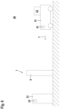
- FIG. 6 shows a further embodiment of the monitoring device 20 according to the invention.
- a driverless transport system 31 transports goods 25 through the protective field 2 to the system 22.
- a navigation system 32 is provided in the driverless transport system 31, which generates position signals.
- the bridging unit 24 can trigger a bridging of the light curtain 1, the functionality of which corresponds to the embodiments of the Figures 4 and 5 corresponds.
Landscapes
- Engineering & Computer Science (AREA)
- General Engineering & Computer Science (AREA)
- Mechanical Engineering (AREA)
- Physics & Mathematics (AREA)
- Life Sciences & Earth Sciences (AREA)
- General Life Sciences & Earth Sciences (AREA)
- General Physics & Mathematics (AREA)
- Geophysics (AREA)
- Geophysics And Detection Of Objects (AREA)
- Emergency Alarm Devices (AREA)
- Burglar Alarm Systems (AREA)
Applications Claiming Priority (1)
| Application Number | Priority Date | Filing Date | Title |
|---|---|---|---|
| DE202022105448.7U DE202022105448U1 (de) | 2022-09-28 | 2022-09-28 | Überwachungseinrichtung |
Publications (2)
| Publication Number | Publication Date |
|---|---|
| EP4354010A1 true EP4354010A1 (fr) | 2024-04-17 |
| EP4354010B1 EP4354010B1 (fr) | 2025-01-15 |
Family
ID=87158017
Family Applications (1)
| Application Number | Title | Priority Date | Filing Date |
|---|---|---|---|
| EP23184039.8A Active EP4354010B1 (fr) | 2022-09-28 | 2023-07-07 | Dispositif de surveillance |
Country Status (3)
| Country | Link |
|---|---|
| EP (1) | EP4354010B1 (fr) |
| DE (1) | DE202022105448U1 (fr) |
| ES (1) | ES3024058T3 (fr) |
Citations (5)
| Publication number | Priority date | Publication date | Assignee | Title |
|---|---|---|---|---|
| DE29920715U1 (de) | 1999-11-25 | 2000-02-24 | Leuze Lumiflex GmbH & Co., 80993 München | Lichtschrankenanordnung zur Überwachung eines Gefahrenbereiches einer Maschine |
| DE20103828U1 (de) * | 2001-03-06 | 2001-06-13 | Fiessler Elektronik OHG, 73734 Esslingen | Sicherheitseinrichtung zur Überwachung eines Durchgangs |
| EP1329662A2 (fr) * | 2002-01-18 | 2003-07-23 | REER S.p.A. | Barrière de sécurité photoélectrique à fonction de désactivation |
| DE102007040692A1 (de) * | 2007-08-29 | 2009-03-05 | Leuze Lumiflex Gmbh + Co. Kg | Optoelektronische Schutzeinrichtung |
| EP2306063A2 (fr) * | 2009-10-02 | 2011-04-06 | Leuze electronic GmbH + Co. KG | Capteur de sécurité |
Family Cites Families (1)
| Publication number | Priority date | Publication date | Assignee | Title |
|---|---|---|---|---|
| DE102008004941B4 (de) * | 2008-01-18 | 2009-10-22 | Sick Ag | Sicherheitsanordnung und Verfahren |
-
2022
- 2022-09-28 DE DE202022105448.7U patent/DE202022105448U1/de active Active
-
2023
- 2023-07-07 EP EP23184039.8A patent/EP4354010B1/fr active Active
- 2023-07-07 ES ES23184039T patent/ES3024058T3/es active Active
Patent Citations (6)
| Publication number | Priority date | Publication date | Assignee | Title |
|---|---|---|---|---|
| DE29920715U1 (de) | 1999-11-25 | 2000-02-24 | Leuze Lumiflex GmbH & Co., 80993 München | Lichtschrankenanordnung zur Überwachung eines Gefahrenbereiches einer Maschine |
| DE20103828U1 (de) * | 2001-03-06 | 2001-06-13 | Fiessler Elektronik OHG, 73734 Esslingen | Sicherheitseinrichtung zur Überwachung eines Durchgangs |
| EP1329662A2 (fr) * | 2002-01-18 | 2003-07-23 | REER S.p.A. | Barrière de sécurité photoélectrique à fonction de désactivation |
| DE102007040692A1 (de) * | 2007-08-29 | 2009-03-05 | Leuze Lumiflex Gmbh + Co. Kg | Optoelektronische Schutzeinrichtung |
| EP2306063A2 (fr) * | 2009-10-02 | 2011-04-06 | Leuze electronic GmbH + Co. KG | Capteur de sécurité |
| DE102009048111B4 (de) | 2009-10-02 | 2020-04-16 | Leuze Electronic Gmbh + Co. Kg | Sicherheitssensor |
Also Published As
| Publication number | Publication date |
|---|---|
| DE202022105448U1 (de) | 2024-01-19 |
| ES3024058T3 (en) | 2025-06-03 |
| EP4354010B1 (fr) | 2025-01-15 |
Similar Documents
| Publication | Publication Date | Title |
|---|---|---|
| EP3339715B1 (fr) | Système de protection d'accès | |
| EP2306063B1 (fr) | Capteur de sécurité | |
| EP2017524B1 (fr) | Barrière lumineuse | |
| EP3910230B1 (fr) | Dispositif de surveillance | |
| DE20321554U1 (de) | Objekterfassung und Lichtgitter | |
| EP3415804B1 (fr) | Dispositif de sécurité | |
| EP3885635B1 (fr) | Dispositif de surveillance permettant de sécuriser l'accès à une zone dangereuse à l'aide d'un capteur de sécurité | |
| EP3575666B1 (fr) | Dispositif de sécurisation d'une zone à risque d'une installation | |
| EP3633413A1 (fr) | Dispositif de sécurité | |
| DE20103828U1 (de) | Sicherheitseinrichtung zur Überwachung eines Durchgangs | |
| EP1826589B1 (fr) | Capteur optique destiné à la surveillance d'une zone de sécurité | |
| EP1837586B1 (fr) | Dispositif de surveillance d'une zone dangereuse près d'une machine | |
| EP4354010B1 (fr) | Dispositif de surveillance | |
| EP3886068B1 (fr) | Dispositif de surveillance et procédé de fonctionnement un dispositif de surveillance | |
| EP3862617B1 (fr) | Dispositif de sécurisation d'une zone dangereuse | |
| DE202022103201U1 (de) | Überwachungseinrichtung | |
| EP3875993B1 (fr) | Dispositif capteur et procédé de fonctionnement d'un dispositif capteur | |
| DE102007036677A1 (de) | Sicherheitssensor | |
| EP3627033B1 (fr) | Dispositif de sécurisation d'une zone à risque d'une installation | |
| EP4614054B1 (fr) | Dispositif de surveillance et procédé de fonctionnement d'un dispositif de surveillance | |
| DE202007019467U1 (de) | Sicherheitssensor | |
| DE102006029643B4 (de) | Vorrichtung zur Überwachung eines Gefahrenbereichs | |
| EP3869240B1 (fr) | Agencement de capteurs et procédé de fonctionnement d'un agencement de capteurs | |
| EP4365477B1 (fr) | Dispositif de surveillance | |
| EP3770481B1 (fr) | Dispositif capteur et procédés de surveillance de zone dangereuse |
Legal Events
| Date | Code | Title | Description |
|---|---|---|---|
| PUAI | Public reference made under article 153(3) epc to a published international application that has entered the european phase |
Free format text: ORIGINAL CODE: 0009012 |
|
| STAA | Information on the status of an ep patent application or granted ep patent |
Free format text: STATUS: THE APPLICATION HAS BEEN PUBLISHED |
|
| AK | Designated contracting states |
Kind code of ref document: A1 Designated state(s): AL AT BE BG CH CY CZ DE DK EE ES FI FR GB GR HR HU IE IS IT LI LT LU LV MC ME MK MT NL NO PL PT RO RS SE SI SK SM TR |
|
| STAA | Information on the status of an ep patent application or granted ep patent |
Free format text: STATUS: REQUEST FOR EXAMINATION WAS MADE |
|
| 17P | Request for examination filed |
Effective date: 20240418 |
|
| RBV | Designated contracting states (corrected) |
Designated state(s): AL AT BE BG CH CY CZ DE DK EE ES FI FR GB GR HR HU IE IS IT LI LT LU LV MC ME MK MT NL NO PL PT RO RS SE SI SK SM TR |
|
| P01 | Opt-out of the competence of the unified patent court (upc) registered |
Effective date: 20240419 |
|
| GRAP | Despatch of communication of intention to grant a patent |
Free format text: ORIGINAL CODE: EPIDOSNIGR1 |
|
| STAA | Information on the status of an ep patent application or granted ep patent |
Free format text: STATUS: GRANT OF PATENT IS INTENDED |
|
| RIC1 | Information provided on ipc code assigned before grant |
Ipc: F16P 3/14 20060101AFI20240930BHEP |
|
| INTG | Intention to grant announced |
Effective date: 20241029 |
|
| GRAS | Grant fee paid |
Free format text: ORIGINAL CODE: EPIDOSNIGR3 |
|
| GRAA | (expected) grant |
Free format text: ORIGINAL CODE: 0009210 |
|
| STAA | Information on the status of an ep patent application or granted ep patent |
Free format text: STATUS: THE PATENT HAS BEEN GRANTED |
|
| AK | Designated contracting states |
Kind code of ref document: B1 Designated state(s): AL AT BE BG CH CY CZ DE DK EE ES FI FR GB GR HR HU IE IS IT LI LT LU LV MC ME MK MT NL NO PL PT RO RS SE SI SK SM TR |
|
| REG | Reference to a national code |
Ref country code: CH Ref legal event code: EP Ref country code: GB Ref legal event code: FG4D Free format text: NOT ENGLISH |
|
| REG | Reference to a national code |
Ref country code: DE Ref legal event code: R096 Ref document number: 502023000463 Country of ref document: DE |
|
| REG | Reference to a national code |
Ref country code: IE Ref legal event code: FG4D Free format text: LANGUAGE OF EP DOCUMENT: GERMAN |
|
| REG | Reference to a national code |
Ref country code: NL Ref legal event code: MP Effective date: 20250115 |
|
| REG | Reference to a national code |
Ref country code: ES Ref legal event code: FG2A Ref document number: 3024058 Country of ref document: ES Kind code of ref document: T3 Effective date: 20250603 |
|
| PG25 | Lapsed in a contracting state [announced via postgrant information from national office to epo] |
Ref country code: NL Free format text: LAPSE BECAUSE OF FAILURE TO SUBMIT A TRANSLATION OF THE DESCRIPTION OR TO PAY THE FEE WITHIN THE PRESCRIBED TIME-LIMIT Effective date: 20250115 |
|
| PG25 | Lapsed in a contracting state [announced via postgrant information from national office to epo] |
Ref country code: RS Free format text: LAPSE BECAUSE OF FAILURE TO SUBMIT A TRANSLATION OF THE DESCRIPTION OR TO PAY THE FEE WITHIN THE PRESCRIBED TIME-LIMIT Effective date: 20250415 |
|
| PG25 | Lapsed in a contracting state [announced via postgrant information from national office to epo] |
Ref country code: FI Free format text: LAPSE BECAUSE OF FAILURE TO SUBMIT A TRANSLATION OF THE DESCRIPTION OR TO PAY THE FEE WITHIN THE PRESCRIBED TIME-LIMIT Effective date: 20250115 |
|
| PG25 | Lapsed in a contracting state [announced via postgrant information from national office to epo] |
Ref country code: PL Free format text: LAPSE BECAUSE OF FAILURE TO SUBMIT A TRANSLATION OF THE DESCRIPTION OR TO PAY THE FEE WITHIN THE PRESCRIBED TIME-LIMIT Effective date: 20250115 |
|
| REG | Reference to a national code |
Ref country code: LT Ref legal event code: MG9D |
|
| PG25 | Lapsed in a contracting state [announced via postgrant information from national office to epo] |
Ref country code: NO Free format text: LAPSE BECAUSE OF FAILURE TO SUBMIT A TRANSLATION OF THE DESCRIPTION OR TO PAY THE FEE WITHIN THE PRESCRIBED TIME-LIMIT Effective date: 20250415 Ref country code: IS Free format text: LAPSE BECAUSE OF FAILURE TO SUBMIT A TRANSLATION OF THE DESCRIPTION OR TO PAY THE FEE WITHIN THE PRESCRIBED TIME-LIMIT Effective date: 20250515 |
|
| PG25 | Lapsed in a contracting state [announced via postgrant information from national office to epo] |
Ref country code: HR Free format text: LAPSE BECAUSE OF FAILURE TO SUBMIT A TRANSLATION OF THE DESCRIPTION OR TO PAY THE FEE WITHIN THE PRESCRIBED TIME-LIMIT Effective date: 20250115 |
|
| PG25 | Lapsed in a contracting state [announced via postgrant information from national office to epo] |
Ref country code: LV Free format text: LAPSE BECAUSE OF FAILURE TO SUBMIT A TRANSLATION OF THE DESCRIPTION OR TO PAY THE FEE WITHIN THE PRESCRIBED TIME-LIMIT Effective date: 20250115 Ref country code: PT Free format text: LAPSE BECAUSE OF FAILURE TO SUBMIT A TRANSLATION OF THE DESCRIPTION OR TO PAY THE FEE WITHIN THE PRESCRIBED TIME-LIMIT Effective date: 20250515 |
|
| PG25 | Lapsed in a contracting state [announced via postgrant information from national office to epo] |
Ref country code: GR Free format text: LAPSE BECAUSE OF FAILURE TO SUBMIT A TRANSLATION OF THE DESCRIPTION OR TO PAY THE FEE WITHIN THE PRESCRIBED TIME-LIMIT Effective date: 20250416 Ref country code: BG Free format text: LAPSE BECAUSE OF FAILURE TO SUBMIT A TRANSLATION OF THE DESCRIPTION OR TO PAY THE FEE WITHIN THE PRESCRIBED TIME-LIMIT Effective date: 20250115 |
|
| PG25 | Lapsed in a contracting state [announced via postgrant information from national office to epo] |
Ref country code: SE Free format text: LAPSE BECAUSE OF FAILURE TO SUBMIT A TRANSLATION OF THE DESCRIPTION OR TO PAY THE FEE WITHIN THE PRESCRIBED TIME-LIMIT Effective date: 20250115 |
|
| PG25 | Lapsed in a contracting state [announced via postgrant information from national office to epo] |
Ref country code: SM Free format text: LAPSE BECAUSE OF FAILURE TO SUBMIT A TRANSLATION OF THE DESCRIPTION OR TO PAY THE FEE WITHIN THE PRESCRIBED TIME-LIMIT Effective date: 20250115 |
|
| PGFP | Annual fee paid to national office [announced via postgrant information from national office to epo] |
Ref country code: ES Payment date: 20250828 Year of fee payment: 3 |
|
| PG25 | Lapsed in a contracting state [announced via postgrant information from national office to epo] |
Ref country code: DK Free format text: LAPSE BECAUSE OF FAILURE TO SUBMIT A TRANSLATION OF THE DESCRIPTION OR TO PAY THE FEE WITHIN THE PRESCRIBED TIME-LIMIT Effective date: 20250115 |
|
| PGFP | Annual fee paid to national office [announced via postgrant information from national office to epo] |
Ref country code: DE Payment date: 20250722 Year of fee payment: 3 |
|
| PG25 | Lapsed in a contracting state [announced via postgrant information from national office to epo] |
Ref country code: IT Free format text: LAPSE BECAUSE OF FAILURE TO SUBMIT A TRANSLATION OF THE DESCRIPTION OR TO PAY THE FEE WITHIN THE PRESCRIBED TIME-LIMIT Effective date: 20250115 |
|
| REG | Reference to a national code |
Ref country code: DE Ref legal event code: R097 Ref document number: 502023000463 Country of ref document: DE |
|
| PGFP | Annual fee paid to national office [announced via postgrant information from national office to epo] |
Ref country code: FR Payment date: 20250725 Year of fee payment: 3 Ref country code: AT Payment date: 20251020 Year of fee payment: 3 |
|
| PG25 | Lapsed in a contracting state [announced via postgrant information from national office to epo] |
Ref country code: EE Free format text: LAPSE BECAUSE OF FAILURE TO SUBMIT A TRANSLATION OF THE DESCRIPTION OR TO PAY THE FEE WITHIN THE PRESCRIBED TIME-LIMIT Effective date: 20250115 Ref country code: CZ Free format text: LAPSE BECAUSE OF FAILURE TO SUBMIT A TRANSLATION OF THE DESCRIPTION OR TO PAY THE FEE WITHIN THE PRESCRIBED TIME-LIMIT Effective date: 20250115 |
|
| PG25 | Lapsed in a contracting state [announced via postgrant information from national office to epo] |
Ref country code: RO Free format text: LAPSE BECAUSE OF FAILURE TO SUBMIT A TRANSLATION OF THE DESCRIPTION OR TO PAY THE FEE WITHIN THE PRESCRIBED TIME-LIMIT Effective date: 20250115 |
|
| PG25 | Lapsed in a contracting state [announced via postgrant information from national office to epo] |
Ref country code: SK Free format text: LAPSE BECAUSE OF FAILURE TO SUBMIT A TRANSLATION OF THE DESCRIPTION OR TO PAY THE FEE WITHIN THE PRESCRIBED TIME-LIMIT Effective date: 20250115 |
|
| PLBE | No opposition filed within time limit |
Free format text: ORIGINAL CODE: 0009261 |
|
| STAA | Information on the status of an ep patent application or granted ep patent |
Free format text: STATUS: NO OPPOSITION FILED WITHIN TIME LIMIT |
|
| 26N | No opposition filed |
Effective date: 20251016 |
|
| PG25 | Lapsed in a contracting state [announced via postgrant information from national office to epo] |
Ref country code: LU Free format text: LAPSE BECAUSE OF NON-PAYMENT OF DUE FEES Effective date: 20250707 |
|
| REG | Reference to a national code |
Ref country code: BE Ref legal event code: MM Effective date: 20250731 |
|
| PG25 | Lapsed in a contracting state [announced via postgrant information from national office to epo] |
Ref country code: BE Free format text: LAPSE BECAUSE OF NON-PAYMENT OF DUE FEES Effective date: 20250731 |