EP4354077A1 - Festbrennstoffgetriebenes geschoss - Google Patents
Festbrennstoffgetriebenes geschoss Download PDFInfo
- Publication number
- EP4354077A1 EP4354077A1 EP22075015.2A EP22075015A EP4354077A1 EP 4354077 A1 EP4354077 A1 EP 4354077A1 EP 22075015 A EP22075015 A EP 22075015A EP 4354077 A1 EP4354077 A1 EP 4354077A1
- Authority
- EP
- European Patent Office
- Prior art keywords
- projectile
- profile
- core piece
- motor case
- solid fuel
- Prior art date
- Legal status (The legal status is an assumption and is not a legal conclusion. Google has not performed a legal analysis and makes no representation as to the accuracy of the status listed.)
- Withdrawn
Links
Images

Classifications
-
- F—MECHANICAL ENGINEERING; LIGHTING; HEATING; WEAPONS; BLASTING
- F42—AMMUNITION; BLASTING
- F42B—EXPLOSIVE CHARGES, e.g. FOR BLASTING, FIREWORKS, AMMUNITION
- F42B10/00—Means for influencing, e.g. improving, the aerodynamic properties of projectiles or missiles; Arrangements on projectiles or missiles for stabilising, steering, range-reducing, range-increasing or fall-retarding
- F42B10/32—Range-reducing or range-increasing arrangements; Fall-retarding means
- F42B10/38—Range-increasing arrangements
-
- F—MECHANICAL ENGINEERING; LIGHTING; HEATING; WEAPONS; BLASTING
- F02—COMBUSTION ENGINES; HOT-GAS OR COMBUSTION-PRODUCT ENGINE PLANTS
- F02K—JET-PROPULSION PLANTS
- F02K1/00—Plants characterised by the form or arrangement of the jet pipe or nozzle; Jet pipes or nozzles peculiar thereto
- F02K1/04—Mounting of an exhaust cone in the jet pipe
-
- F—MECHANICAL ENGINEERING; LIGHTING; HEATING; WEAPONS; BLASTING
- F02—COMBUSTION ENGINES; HOT-GAS OR COMBUSTION-PRODUCT ENGINE PLANTS
- F02K—JET-PROPULSION PLANTS
- F02K7/00—Plants in which the working fluid is used in a jet only, i.e. the plants not having a turbine or other engine driving a compressor or a ducted fan; Control thereof
- F02K7/10—Plants in which the working fluid is used in a jet only, i.e. the plants not having a turbine or other engine driving a compressor or a ducted fan; Control thereof characterised by having ram-action compression, i.e. aero-thermo-dynamic-ducts or ram-jet engines
- F02K7/105—Plants in which the working fluid is used in a jet only, i.e. the plants not having a turbine or other engine driving a compressor or a ducted fan; Control thereof characterised by having ram-action compression, i.e. aero-thermo-dynamic-ducts or ram-jet engines using a solid fuel
-
- F—MECHANICAL ENGINEERING; LIGHTING; HEATING; WEAPONS; BLASTING
- F02—COMBUSTION ENGINES; HOT-GAS OR COMBUSTION-PRODUCT ENGINE PLANTS
- F02K—JET-PROPULSION PLANTS
- F02K9/00—Rocket-engine plants, i.e. plants carrying both fuel and oxidant therefor; Control thereof
- F02K9/97—Rocket nozzles
-
- F—MECHANICAL ENGINEERING; LIGHTING; HEATING; WEAPONS; BLASTING
- F42—AMMUNITION; BLASTING
- F42B—EXPLOSIVE CHARGES, e.g. FOR BLASTING, FIREWORKS, AMMUNITION
- F42B12/00—Projectiles, missiles or mines characterised by the warhead, the intended effect, or the material
- F42B12/02—Projectiles, missiles or mines characterised by the warhead, the intended effect, or the material characterised by the warhead or the intended effect
- F42B12/04—Projectiles, missiles or mines characterised by the warhead, the intended effect, or the material characterised by the warhead or the intended effect of armour-piercing type
- F42B12/06—Projectiles, missiles or mines characterised by the warhead, the intended effect, or the material characterised by the warhead or the intended effect of armour-piercing type with hard or heavy core; Kinetic energy penetrators
-
- F—MECHANICAL ENGINEERING; LIGHTING; HEATING; WEAPONS; BLASTING
- F42—AMMUNITION; BLASTING
- F42B—EXPLOSIVE CHARGES, e.g. FOR BLASTING, FIREWORKS, AMMUNITION
- F42B5/00—Cartridge ammunition, e.g. separately-loaded propellant charges
- F42B5/02—Cartridges, i.e. cases with charge and missile
- F42B5/10—Cartridges, i.e. cases with charge and missile with self-propelled bullet
Definitions
- the present invention relates to solid fuel assisted gun-launched solid fuel propelled projectiles.
- solid fuel propelled projectiles are known, e.g. from US4573412 , disclosing a rocket projectile, comprising an elongated projectile motor case and a core piece to form a combustion chamber between the motor case and core piece.
- An exhaust nozzle profile is provided on the rear side of the combustion chamber.
- a special type of solid fuel projectiles are gun-launched projectiles, e.g. described in Veraar, R.G., Ramjet Applications of the Solid Fuel Combustion Chamber, TNO, Symposium Proc. ⁇ High Speed Airbreathing Propulsion, the Solid Fuel Combustion Chamber and Beyond', Rijswijk, The Netherlands, June 7, 1991 .
- the disclosed projectiles are of a ramjet type, comprising an air intake provided on the front side of the projectile providing air into the combustion chamber.
- This has an advantage, since the projectile does not need an additional oxidator for converting the solid fuel in the combustion chamber. This also leads to a reduced volume and mass of the fuel and thus the projectile, since it does not take the oxidator on board.
- These gun-launched projectiles may ignite the solid fuel ramjet (SFRJ) motor incorporated in it, due to the high velocities of the launch or due to the gun propellant.
- the SFRJ motor is at least active over a part of the flight trajectory, and will typically start just after launch by self-ignition.
- Typical launching velocities are well above 1 Mach, for instance 4 Mach.
- the projectiles may be of a KE penetrator type, which is the Kinetic Energy long rod penetrator, of a high relative density rod with a high length/diameter ratio, so that a very high kinetic energy impact occurs on a small diameter.
- a concentrated deposition of kinetic energy occurs on the target, which aids to its penetrating power
- PELE type which is a ⁇ penetrator with enhanced lateral efficiency'. This is a projectile that is more aimed at fragmentating on a larger impact area, and not specifically targeted at penetrating power.
- the PELE type is provided as an elongated object that, instead of a high relative density central rod is provided with a high relative density mantle. Both variants may be provided with a SFRJ motor or any other solid fuel propelled motor.
- the SFRJ motor is a jet motor without moving parts, which uses solid state fuel provided on the mantle and/or core, wherein either a core is of a high relative density to provide a KE type penetrator, or the mantle is of a high relative density to provide a PELE type penetrator.
- an advantage of a solid fuel propelled projectile is that it will not significantly reduce its speed due to air impact, which also contributes to the kinetic energy that can be transferred on impact, which aids to its penetrating power.
- a specific challenge for gun launched, solid fuel propelled projectiles is to provide a motor design that withstands the large accelerations on launch, especially to the exhaust nozzle of the solid fuel motor. While solid fuel propelled projectiles reach higher velocities than non-propelled ones, there is also a difficulty in providing a motor design that accommodates sufficient long core pieces, due to the structural complexity of the motor. Furthermore, there is a difficulty in that for conventional cartridges, containing the gun propellants that will launch the projectile, the amount of explosive material is volumetric in communication with the length of the projectile. Thus, there is a limited length possible for the projectile, in view of the necessary amount of gun propellant material to launch it. Furthermore, additional support material to support and protect the solid fuel motor such as sabots of the known type may also reduce the available volumetric amount of gun propellant.
- a gun-launchable solid fuel propelled projectile formed by an elongated projectile motor case and/or a core piece having solid fuel provided thereon to form a combustion chamber between the motor case and core piece; and an exhaust nozzle provided on the rear side of the combustion chamber; said exhaust nozzle provided by a ring element extending rearwards of the motor case.
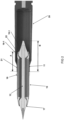
- a gun-launchable solid fuel propelled projectile 10 is formed by an elongated projectile motor case 11 and a core 12.
- a combustion chamber 14 between the motor case 11 and core piece 12 is formed by fuel provided 15 provided on an inner wall of the motor case.
- the combustion chamber 14 may be designed according to known conventional principles and is not limited to a solid fuel on the motor case 11, but solid fuel may also be provided on the core piece 12 and/or a combination is possible.
- An exhaust nozzle 16 is provided on the rear side of the combustion chamber 14. The exhaust nozzle provided by a ring element 16-1 extending rearwards of the motor case 11, and an aerospike profile 16-2 surrounding the core piece 12.
- the aerospike profile 16-2 freely extends rearward of the ring element 16-1, that is, the profile is not flanked by an additional nozzle structure. Due to the absence of such further nozzle structure, the advantage of this shape is that it can extend much further into a cartridge, and at the same time extend a central core piece 12, which aids to its penetrating power, yet without additional nozzle structure that would reduce the available volumetric amount of gun propellant. Thus, the only extension that need to be accommodated is the central core piece 12 that is provided with the aerospike profile 16-2, which is volumetrically relatively limited in size and can yet increase the penetrating power of the projectile substantially.
- Such an aerospike nozzle profile is a profile that can be designed by known principles and is characterised by, seen in rearward direction, a convergent and then divergent profiled ring 16-2 opposite a divergent central aerospike profile, seen in lateral direction of aerospike profile 16-1.
- the convergent divergent nozzle structure will provide a combustion gas flow alongside the converging end profile of the aerospike, hence the name, and will concentrate the ejected gas flow along an axial direction of the projectile in rearward direction, optimally using it to generate forward thrust.
- the shown solid fuel propelled projectile is of a ramjet type, comprising an air intake 17 provided on the front side of the projectile providing air into the combustion chamber.
- This has an advantage, since the projectile does not need an additional oxidator on board for converting the solid fuel in the combustion chamber.
- fuel is used both for self oxidizing fuel, containing an oxidator, typically used as rocket fuel or rocket propellant; and non-self oxidizing fuel; where an additional oxidator is provided from the surroundings, typically known as ramjet fuel.
- an embodiment may be feasible that contains a oxidator and obviates the inlet structure. Ignition of the solid fuel 15 may be ignited by the gun propellant or by self ignition, e.g.
- the air intake 17 may be of a bicone axisymmetric air intake that is per se known to the skilled person.
- Other intake forms are possible, for instance: a single cone design, o triple cone, quadrupel cone, etc.
- the intake may be segmented (non-axisymetric), may be of an 'external compression' type, a 'mixed compression' type, (as illustrated) an 'internal compression'; or a 'pitot' intake also known to the skilled person.
- the design of Figure 1 has a front end that has sharp aerodynamic extension 18 to the rod 12 that functions as a lead in to the intake duct 17.
- the embodiment of Figure 1 is designed as a Kinetic Energy (KE) embodiment, wherein the core piece 12 is provided as a penetrator rod of a high relative density material to enhance kinetic impact. Suitable materials may be Tungsten, depleted Uranium etc.
- a rod length can be extended more than 5%, or even more than 7%, which significantly increases the impacting power. Length to diameter ratio may be in the order of 15 or higher, for instance higher than 18.5 or even ranging in the order 19-21.
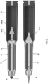
- FIG 2 shows the embodiment of a projectile 10, in this case, a SFRJ assisted KE penetrator, similar or identical to Figure 1 , now held in a launching cartridge 20.
- the projectile 10 is stabilized by a rotating band 19 to the cartridge wall 21, that abuts the projectile mantel 11 and provided for obtaining spin.
- Other stabilizing means may be provided, such as stabilizing fins.
- the projectile outer wall extends over a length A into the cartridge 20, and the central core piece extends over a length B into the cartridge, which is substantially larger than A, for instance, larger than 20 mm, depending on the calibre type used.
- the rod itself is of a very limited diameter, in view of the required length to diameter ratio, and the aerospike profile 16-1 is also limited in volume respective to the length A, in a standard cartridge, more volumetric space is available for gun propellants, which aids to the range and velocities wherein the projectile can be engaged.
- the design is not limited to specific ratios or geometric dimensions but can be adapted according to an intended use.
- the projectile includes a mantle that is designed as a PELE device, with a high density material provided in the motor case 11.
- Figure 2 shows, in contrast to the Figure 1 structure, an additional pusher plate 22, which is not part of the projectile 10 but is used as a launching aid. Accordingly a pusher plate 22 at least partly surrounds the aerospike profile 16-2 and abuts ring element 16-1 and the motor case 11, and pusher plate 22 as temporary rear structure extends into the cartridge 20.
- the pusher plate design is structured to support the exhaust nozzle 16, formed by the ring element 16-1 and aerospike profile 16-2 that may be structurally combined by one or more struts.
- the pusher plate may be annular in shape to protect the nozzle structure.
- the pusher plate may close the nozzle keel (orifice) and mechanically supports both the central core piece 12 and the motor case 11.
- the aerospike profile 16-1 will only partly be exposed to launching forces, which may also be partly deflected to the pusher plate 22 due to its spike design.
- the pusher plate 22 may be designed to transduce some of the ignition of the gun propellant to the solid fuel of the ramjet motor, in order to ignite it e.g. by the compression of the air in the intake and corresponding temperature raise. In other embodiments, ignition of the solid fuel may be achieved by the impacting pressure and corresponding temperature raise of the inlet structure itself.
- Figure 3 shows another embodiment of a solid fuel ramjet projectile.
- This profile has a potential of even using a longer core piece, further aiding to its penetrating power or the potential of using more gun propellant since the projectile may be less deep inserted into the cartridge, so that more gun propellant can be provided in the cartridge in order to launch the projectile.
- the embodiment is provided with a rearward part 16-1a that at least partly forms the aerospike profile, when launched.
- the core piece 12 is slidable in said forward and rearward struts, and wherein a locking means is provided to lock the core piece relative to the motor case 11, when the core piece is launched forward, relative to the motor case 11.
- the locking means can be any structure that fixedly secures the relative position of the core piece 12 relative to the motor case. In the figure, this could be realized by a press fit connection, e.g. the core piece, by means of aerospike 16-1b press fitted to the rearward strut 16-1a.
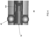
- a form fitting connection may be used, e.g. of the type disclosed in Figure 4 , that shows a spring loaded ball lock.
- a spring loaded ball lock 40 may secure the relative position of the central piece 12 relative to the motor case 11, e.g. by pushing spring loaded balls 41 into a corresponding depression 121 provided on the central core 12.
- the inlet structure Before launch, the inlet structure may be protected by a removable nose cap 31.
- the nose cape may be constructed to be removed by hand, but it may also be removed by the protruding force F that is exerted on the cap 31 when rod 12 slides forward, relative to the motor case 11, into flight position.
- the flight position of the slidable rod 12 demonstrated in Figure 3 may be assumed prior, during or after launch from cartridge 20, and may be aided by ignition of the gun propellants.
Landscapes
- Engineering & Computer Science (AREA)
- General Engineering & Computer Science (AREA)
- Chemical & Material Sciences (AREA)
- Combustion & Propulsion (AREA)
- Mechanical Engineering (AREA)
- Physics & Mathematics (AREA)
- Fluid Mechanics (AREA)
- Toys (AREA)
- Portable Nailing Machines And Staplers (AREA)
Priority Applications (5)
| Application Number | Priority Date | Filing Date | Title |
|---|---|---|---|
| EP22075015.2A EP4354077A1 (de) | 2022-10-14 | 2022-10-14 | Festbrennstoffgetriebenes geschoss |
| PCT/NL2023/050535 WO2024080873A1 (en) | 2022-10-14 | 2023-10-13 | A solid fuel propelled projectile |
| EP23790420.6A EP4602322A1 (de) | 2022-10-14 | 2023-10-13 | Festbrennstoffgetriebenes geschoss |
| AU2023358215A AU2023358215A1 (en) | 2022-10-14 | 2023-10-13 | A solid fuel propelled projectile |
| KR1020257015785A KR20250095640A (ko) | 2022-10-14 | 2023-10-13 | 고체 연료 추진 발사체 |
Applications Claiming Priority (1)
| Application Number | Priority Date | Filing Date | Title |
|---|---|---|---|
| EP22075015.2A EP4354077A1 (de) | 2022-10-14 | 2022-10-14 | Festbrennstoffgetriebenes geschoss |
Publications (1)
| Publication Number | Publication Date |
|---|---|
| EP4354077A1 true EP4354077A1 (de) | 2024-04-17 |
Family
ID=84887379
Family Applications (2)
| Application Number | Title | Priority Date | Filing Date |
|---|---|---|---|
| EP22075015.2A Withdrawn EP4354077A1 (de) | 2022-10-14 | 2022-10-14 | Festbrennstoffgetriebenes geschoss |
| EP23790420.6A Pending EP4602322A1 (de) | 2022-10-14 | 2023-10-13 | Festbrennstoffgetriebenes geschoss |
Family Applications After (1)
| Application Number | Title | Priority Date | Filing Date |
|---|---|---|---|
| EP23790420.6A Pending EP4602322A1 (de) | 2022-10-14 | 2023-10-13 | Festbrennstoffgetriebenes geschoss |
Country Status (4)
| Country | Link |
|---|---|
| EP (2) | EP4354077A1 (de) |
| KR (1) | KR20250095640A (de) |
| AU (1) | AU2023358215A1 (de) |
| WO (1) | WO2024080873A1 (de) |
Citations (3)
| Publication number | Priority date | Publication date | Assignee | Title |
|---|---|---|---|---|
| US4573412A (en) | 1984-04-27 | 1986-03-04 | The United States Of America As Represented By The Secretary Of The Army | Plug nozzle kinetic energy penetrator rocket |
| FR2821420A1 (fr) * | 2001-02-26 | 2002-08-30 | Francois Louis Desire Ragache | Ogive perforante autopropulsee pour tir tendu longue portee |
| KR102028673B1 (ko) * | 2019-04-17 | 2019-10-04 | 국방과학연구소 | 추진기관의 추력 조절 장치 |
-
2022
- 2022-10-14 EP EP22075015.2A patent/EP4354077A1/de not_active Withdrawn
-
2023
- 2023-10-13 KR KR1020257015785A patent/KR20250095640A/ko active Pending
- 2023-10-13 AU AU2023358215A patent/AU2023358215A1/en active Pending
- 2023-10-13 WO PCT/NL2023/050535 patent/WO2024080873A1/en not_active Ceased
- 2023-10-13 EP EP23790420.6A patent/EP4602322A1/de active Pending
Patent Citations (3)
| Publication number | Priority date | Publication date | Assignee | Title |
|---|---|---|---|---|
| US4573412A (en) | 1984-04-27 | 1986-03-04 | The United States Of America As Represented By The Secretary Of The Army | Plug nozzle kinetic energy penetrator rocket |
| FR2821420A1 (fr) * | 2001-02-26 | 2002-08-30 | Francois Louis Desire Ragache | Ogive perforante autopropulsee pour tir tendu longue portee |
| KR102028673B1 (ko) * | 2019-04-17 | 2019-10-04 | 국방과학연구소 | 추진기관의 추력 조절 장치 |
Non-Patent Citations (1)
| Title |
|---|
| VERAAR, R.G.: "Ramjet Applications of the Solid Fuel Combustion Chamber", TNO, SYMPOSIUM PROC. `HIGH SPEED AIRBREATHING PROPULSION, THE SOLID FUEL COMBUSTION CHAMBER AND BEYOND', RIJSWIJK, THE NETHERLANDS, 7 June 1991 (1991-06-07) |
Also Published As
| Publication number | Publication date |
|---|---|
| KR20250095640A (ko) | 2025-06-26 |
| WO2024080873A1 (en) | 2024-04-18 |
| EP4602322A1 (de) | 2025-08-20 |
| AU2023358215A1 (en) | 2025-05-01 |
Similar Documents
| Publication | Publication Date | Title |
|---|---|---|
| US4944226A (en) | Expandable telescoped missile airframe | |
| US6234082B1 (en) | Large-caliber long-range field artillery projectile | |
| US6405653B1 (en) | Supercavitating underwater projectile | |
| JP3065669B2 (ja) | 水中の目標に対して使用するための航学力学的に安定した弾丸システム | |
| US4539911A (en) | Projectile | |
| US9823053B1 (en) | Solid-fuel ramjet ammunition | |
| EP2422162B1 (de) | Täuschkörper mit gewichteter nase und geringer beschädigung durch fremdkörper | |
| EP0683376B1 (de) | Rohrabgeschossene Flugkörper die mit Luftatmenden Triebwerken unterstützt sind | |
| KR101494393B1 (ko) | 이중 추력 로켓 추진기관 | |
| WO2003016849A2 (en) | Method and apparatus for testing engines | |
| US2946261A (en) | Peripheral nozzle spinner rocket | |
| CN101113882A (zh) | 一种降低弹体激波阻力的弹体结构及方法 | |
| EP4354077A1 (de) | Festbrennstoffgetriebenes geschoss | |
| KR20210019189A (ko) | 램제트 기관을 구비하는 발사체 | |
| KR101609507B1 (ko) | 사거리 연장형 램제트 추진탄 | |
| RU2751311C1 (ru) | Способ увеличения дальности полета активно-реактивного снаряда и активно-реактивный снаряд с моноблочной комбинированной двигательной установкой (варианты) | |
| RU2538645C1 (ru) | Способ расширения зоны применимости бикалиберной ракеты и бикалиберная ракета, реализующая способ | |
| RU2686546C1 (ru) | Бронебойный активно-реактивный снаряд | |
| US9169806B2 (en) | Propulsion system for flying machine, particularly for a missile | |
| EP4232700B1 (de) | Integriertes antriebs- und gefechtskopfsystem für eine artillerierunde | |
| RU2754475C1 (ru) | Гиперзвуковой реактивный снаряд | |
| US4170875A (en) | Caseless rocket design | |
| Krishnan et al. | Design and control of solid-fuel ramjet for pseudovacuum trajectories | |
| US10690443B1 (en) | Rocket motor with combustion product deflector | |
| US6478250B1 (en) | Propulsive torque motor |
Legal Events
| Date | Code | Title | Description |
|---|---|---|---|
| STAA | Information on the status of an ep patent application or granted ep patent |
Free format text: STATUS: UNKNOWN |
|
| PUAI | Public reference made under article 153(3) epc to a published international application that has entered the european phase |
Free format text: ORIGINAL CODE: 0009012 |
|
| STAA | Information on the status of an ep patent application or granted ep patent |
Free format text: STATUS: THE APPLICATION HAS BEEN PUBLISHED |
|
| AK | Designated contracting states |
Kind code of ref document: A1 Designated state(s): AL AT BE BG CH CY CZ DE DK EE ES FI FR GB GR HR HU IE IS IT LI LT LU LV MC ME MK MT NL NO PL PT RO RS SE SI SK SM TR |
|
| STAA | Information on the status of an ep patent application or granted ep patent |
Free format text: STATUS: THE APPLICATION IS DEEMED TO BE WITHDRAWN |
|
| 18D | Application deemed to be withdrawn |
Effective date: 20241018 |