EP4354100A1 - Dispositif et procédé de mesure de vibrations - Google Patents
Dispositif et procédé de mesure de vibrations Download PDFInfo
- Publication number
- EP4354100A1 EP4354100A1 EP21945113.5A EP21945113A EP4354100A1 EP 4354100 A1 EP4354100 A1 EP 4354100A1 EP 21945113 A EP21945113 A EP 21945113A EP 4354100 A1 EP4354100 A1 EP 4354100A1
- Authority
- EP
- European Patent Office
- Prior art keywords
- light
- light pulses
- phase
- vibration
- frequency
- Prior art date
- Legal status (The legal status is an assumption and is not a legal conclusion. Google has not performed a legal analysis and makes no representation as to the accuracy of the status listed.)
- Pending
Links
Images


Classifications
-
- G—PHYSICS
- G01—MEASURING; TESTING
- G01H—MEASUREMENT OF MECHANICAL VIBRATIONS OR ULTRASONIC, SONIC OR INFRASONIC WAVES
- G01H9/00—Measuring mechanical vibrations or ultrasonic, sonic or infrasonic waves by using radiation-sensitive means, e.g. optical means
- G01H9/004—Measuring mechanical vibrations or ultrasonic, sonic or infrasonic waves by using radiation-sensitive means, e.g. optical means using fibre optic sensors
-
- G—PHYSICS
- G01—MEASURING; TESTING
- G01D—MEASURING NOT SPECIALLY ADAPTED FOR A SPECIFIC VARIABLE; ARRANGEMENTS FOR MEASURING TWO OR MORE VARIABLES NOT COVERED IN A SINGLE OTHER SUBCLASS; TARIFF METERING APPARATUS; MEASURING OR TESTING NOT OTHERWISE PROVIDED FOR
- G01D5/00—Mechanical means for transferring the output of a sensing member; Means for converting the output of a sensing member to another variable where the form or nature of the sensing member does not constrain the means for converting; Transducers not specially adapted for a specific variable
- G01D5/26—Mechanical means for transferring the output of a sensing member; Means for converting the output of a sensing member to another variable where the form or nature of the sensing member does not constrain the means for converting; Transducers not specially adapted for a specific variable characterised by optical transfer means, i.e. using infrared, visible, or ultraviolet light
- G01D5/32—Mechanical means for transferring the output of a sensing member; Means for converting the output of a sensing member to another variable where the form or nature of the sensing member does not constrain the means for converting; Transducers not specially adapted for a specific variable characterised by optical transfer means, i.e. using infrared, visible, or ultraviolet light with attenuation or whole or partial obturation of beams of light
- G01D5/34—Mechanical means for transferring the output of a sensing member; Means for converting the output of a sensing member to another variable where the form or nature of the sensing member does not constrain the means for converting; Transducers not specially adapted for a specific variable characterised by optical transfer means, i.e. using infrared, visible, or ultraviolet light with attenuation or whole or partial obturation of beams of light the beams of light being detected by photocells
- G01D5/353—Mechanical means for transferring the output of a sensing member; Means for converting the output of a sensing member to another variable where the form or nature of the sensing member does not constrain the means for converting; Transducers not specially adapted for a specific variable characterised by optical transfer means, i.e. using infrared, visible, or ultraviolet light with attenuation or whole or partial obturation of beams of light the beams of light being detected by photocells influencing the transmission properties of an optical fibre
- G01D5/35338—Mechanical means for transferring the output of a sensing member; Means for converting the output of a sensing member to another variable where the form or nature of the sensing member does not constrain the means for converting; Transducers not specially adapted for a specific variable characterised by optical transfer means, i.e. using infrared, visible, or ultraviolet light with attenuation or whole or partial obturation of beams of light the beams of light being detected by photocells influencing the transmission properties of an optical fibre using other arrangements than interferometer arrangements
- G01D5/35354—Sensor working in reflection
- G01D5/35358—Sensor working in reflection using backscattering to detect the measured quantity
Definitions
- the present disclosure relates to a vibration measuring instrument and a vibration measuring method for performing DAS-P.
- DAS distributed acoustic sensing
- vibration sensing is performed by capturing changes, in the optical path length of an optical fiber, resulting from physical vibration applied to the optical fiber. By detecting vibration, it is possible to detect movement or the like of an object around the measurement target optical fiber.
- DAS-intensity As a method for detecting backscattered light in DAS, there is a technique for measuring the intensity of light scattered from each point on the measurement target optical fiber, and observing temporal changes in the intensity of the scattered light. This technique is called DAS-intensity (DAS-I). Although DAS-I characteristically simplifies the device configuration, it is impossible to quantitatively calculate a change in the optical path length of a fiber, resulting from vibration, on the basis of the scattered light intensity, and therefore, DAS-I is a qualitative measurement method (Non Patent Literature 2).
- DAS-phase which is a technique for measuring the phase of light scattered from each point on the measurement target optical fiber and observing temporal changes in the phase
- DAS-P DAS-phase
- the device configuration and the signal processing in DAS-P are more complicated than those in DAS-I
- a phase changes linearly with respect to changes, in the optical path length of a fiber, resulting from vibration, and the rate of change is also uniform in the longitudinal direction of the optical fiber.
- vibration can be quantitatively measured, and the vibration applied to the measurement target optical fiber can be faithfully reproduced (Non Patent Literature 2, for example).
- pulsed light is injected into the measurement target optical fiber, and the phase of scattered light at a time t for injecting the pulsed light is measured, in a distributed manner, in the longitudinal direction of the optical fiber. That is, the phase ⁇ (l, t) of the scattered light is measured, with the distance from the incidence end of the optical fiber set to a distance l.
- the time for measuring at the point of the distance l is later than the time for injecting the pulse by the time during which the pulsed light propagates from the incidence end to the distance l. Further, it should be noted that the time at which a measuring instrument measures is delayed by the time required for the scattered light to return to the incidence end. It is known that the magnitude of physical vibration applied to the section from the distance l to a distance l+ ⁇ l at each time nT is proportional to the difference ⁇ (l, nT) between the phase ⁇ (l+ ⁇ l, nT) at the distance l+ ⁇ l and the phase ⁇ (l, nT) at the distance l. That is, the expression shown below is satisfied when time zero is the reference time. [Math.
- Non Patent Literature 1 As device configurations for detecting the phase of scattered light, there are a direct detection configuration that directly detects backscattered light from the measurement target optical fiber with a photodiode or the like, and a configuration that uses coherent detection to detect backscattered light multiplexed with separately prepared reference light (Non Patent Literature 1, for example).
- Mechanisms for performing coherent detection and calculating a phase are specifically classified into two kinds, which are a mechanism for software-based processing using Hilbert transform, and a mechanism for hardware-based processing using a 90-degree optical hybrid.
- an in-phase component I(l, nT) and a quadrature component Q(l, nT) of scattered light are acquired, and the phase is calculated according to the expression shown below.
- ⁇ cal l nT Arctan Q l nT I l nT
- an output value by the four-quadrant arctangent operator Arctan is within the range of (- ⁇ , ⁇ ] in radians, and 2m ⁇ + ⁇ (l, nT) all have the same vector direction in an x-y plane (m being an integer), and accordingly, the uncertainty of 2m ⁇ exists in ⁇ cal (l, nT) calculated as above. Therefore, as a more accurate evaluation method for ⁇ (l, nT), signal processing such as phase unwrapping is further performed.
- phase after unwrapping is represented by ⁇ cal unwrap in general phase unwrapping
- ⁇ cal unwrap is set to be the same as ⁇ cal at the start point of the phase unwrapping, and ⁇ cal unwrap (l, pT) to ⁇ cal unwrap (l, (p+1)T) are then sequentially calculated as shown below, with p representing an integer.
- noise of the measuring instrument such as thermal noise of a photodiode (PD) for detecting light, noise at the subsequent electrical stage, or shot noise caused by light. Therefore, the intensity and the phase of the scattered light to be measured are also affected by the noise of the measuring instrument.
- PD photodiode
- the large influence of noise of the measuring instrument increases not only the uncertainty of the phase, but also the probability of a measurement value being significantly different from the ideal phase value to be obtained in the absence of noise.
- the direction of the vector of no noise corresponds to the phase to be measured.
- the vector is directed in the opposite direction, which increases the probability that a difference between the phase value to be actually measured and the ideal phase value of no noise is about the ⁇ radian.
- the influence of noise of the measuring instrument is increased by decreasing the intensity of scattered light, as long as the noise of the measuring instrument can be regarded as the same level at each point and each time. Accordingly, increasing the intensity of scattered light at each point and each time can reduce the influence of noise of the measuring instrument.
- Patent Literature 1 a suggested phase measurement method and a suggested signal processing device capable of reducing the influence of noise of a measuring instrument without any increase in the peak intensity of the incident light pulse in measuring the phase of scattered light in DAS-P.
- pulsed light obtained by arraying and wavelength-multiplexing pulses with different optical frequency components at time intervals at which changes in the fiber state resulting from vibration are negligible
- scattered light vectors are created by plotting scattered light with the respective wavelengths from the measurement target optical fiber in a two-dimensional plane in which the in-phase components are represented by the abscissa axis and the quadrature components are represented by the ordinate axis
- directions of the created scattered light vectors are matched by rotating the created scattered light vectors for each wavelength at each point on the measurement target optical fiber
- a new vector is generated by averaging the vectors having the directions matched
- a phase is calculated from the values of the in-phase component and the quadrature component of the generated new vector.
- Non Patent Literature 4 has been suggested as a method for solving the above problem.
- pulsed light obtained by arraying pulses with different optical frequency components at equal intervals and performing wavelength-multiplexing thereon is injected into the measurement target optical fiber, and scattered light with the respective wavelengths from the measurement target optical fiber is plotted in a two-dimensional plane in which the in-phase components are represented by the abscissa axis and the quadrature components are represented by the ordinate axis, to create scattered light vectors.
- the phase is calculated from the obtained scattered light vectors.
- the sampling rate upper limit determined from the measurement distance on condition of a single optical frequency is represented by f s
- the sampling rate upper limit can be N ⁇ f s by N-wave multiplexing.
- the wavelength multiplexing number "N" is a natural number.
- Non Patent Literature 4 suggests a method for correctly estimating the frequency of a signal having a vibrational frequency exceeding the Nyquist frequency f v on condition of the single frequency, by first calculating the temporal phase difference of the respective optical frequencies and then combining the calculated phase differences of the respective optical frequencies. That is, it is possible to estimate frequencies up to the frequency N ⁇ f v without aliasing. By this suggested technique, however, the angular differences between the respective optical frequencies are not obtained, and therefore, any vibrational waveform cannot be measured.
- Non Patent Literature 5 suggests a measurement method capable of measuring a vibrational waveform under the condition that the sampling rate upper limit is increased to N ⁇ f s , by correcting the angular differences between the respective optical frequencies using a correction frequency.
- a compensation optical frequency is used separately from the main optical frequencies to improve the sampling rate, and a probe pulse train is used so that a component regarding a main optical frequency and a component regarding the compensation optical frequency regularly are injected into the measurement target fiber at timings allowed to be regarded as the same times.
- the angular difference between the component regarding the main optical frequency and the component regarding the compensation optical frequency is corrected, and the angular differences between the respective main optical frequencies are corrected.
- the upper limit of the absolute value of the magnitude of a phase change at adjacent sampling points is ⁇ . Even within the range of the Nyquist frequency or lower, as the vibrational frequency becomes higher, the phase change at adjacent sampling points becomes larger. Therefore, when the vibration amplitude becomes larger, a further requirement is added to the upper limit of the measurable vibrational frequencies.
- a vibrational waveform can be measured, and accordingly, this method is also effective in alleviating such constraints.
- Non Patent Literature 5 also suggests an optical frequency pulse forming method and a reception signal processing method for simultaneously implementing a frequency multiplexing method by which pulses with different optical frequencies are injected at different times so as to improve the sampling rate, and the frequency multiplexing method disclosed in Patent Literature 1 as a countermeasure against fading.
- n the effective refractive index of the fiber
- ⁇ p represents the Poisson's ratio
- p 11 and p 12 represent the strain-optic tensor components.
- ⁇ 1555 nm near a normal communication wavelength band
- n 1.47
- ⁇ p 0.17
- p 11 0.121
- p 12 0.271. Therefore, it is known that the following expression is satisfied (Non Patent Literature 8).
- ⁇ K ⁇ l
- K 4.6 ⁇ 10 6 m -1 .
- Non Patent Literature 5 pulses with different optical frequencies are injected at different times, to improve the sampling rate.
- the band occupied by scattered light of each optical frequency component is in the shape of a sinc function, and therefore, side lobes are present.
- the side lobes cause crosstalk in which the bands, occupied by scattered light with the respective optical frequency components, overlap with each other. Due to this crosstalk, a component regarding a band near an optical frequency fm of the side lobes of scattered light with another optical frequency component fn that is injected at another time is added to the signal of scattered light of the optical frequency component fm, and both components cannot be separated by a digital bandpass filter or the like.
- Patent Literature 1 JP 2020-169904 A
- the present disclosure aims to reduce crosstalk between different optical frequency components, and reduce erroneous detection of vibration and distortion of a vibrational waveform.
- the outer shape of light pulses to be injected the measurement target optical fiber is a waveform with small side lobes in the frequency domain.
- the degree of overlapping between the bands occupied by scattered light with the respective optical frequency components is lowered, and the problem of erroneous detection of vibration in a section withdrawn from the spot at which the vibration causing the crosstalk is actually generated is alleviated.
- a waveform such as a raised cosine wave, having a smaller spectral side lobe than that of a rectangular wave is used as a pulse outer shape of each optical frequency component.
- a vibration measuring instrument and a vibration measuring method involves a measuring instrument that repeatedly injects a plurality of light pulses with different optical frequencies into an optical fiber, and performs DAS-P.
- light pulses having a waveform with a spectral side lobe smaller than a side lobe of a rectangular wave are used as the plurality of light pulses.
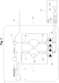
- Fig. 1 is a diagram for explaining a vibration detection system that performs vibration detection by DAS-P according to this embodiment.
- the vibration detection system includes: a light source that injects a frequency-multiplexed light pulse train into one end of the measurement target optical fiber; a light receiver that receives scattered light of each wavelength returned to the one end of the measurement target optical fiber; and a signal processing unit that observes vibration of the measurement target optical fiber as a temporal change in the phase component of the scattered light.
- a vibration measuring instrument 31 includes a CW light source 1, a coupler 2, an optical modulator 3, a 90-degree optical hybrid 7, and balance detectors (13 and 14).
- a CW light source 1, a coupler 2, and an optical modulator 3 correspond to the light source.
- a 90-degree optical hybrid 7 and balance detectors (13 and 14) correspond to the light receiver. The light receiver performs coherent detection, using the 90-degree optical hybrid 7.
- a signal processing device 17 corresponds to the signal processing unit. However, it is not always necessary to use a 90-degree optical hybrid for the reception system, and some other device or signal processing may be used, as long as an in-phase component and a quadrature component of scattered light can be measured.
- the signal processing device 17 of the present disclosure can also be implemented in a computer and a program, and the program can be recorded on a recording medium or be provided through a network.
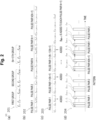
- a vibration measuring instrument 31 measures scattered light from a measurement target optical fiber 6 as follows. Continuous light with a single wavelength that is an optical frequency f 0 is emitted from the CW light source 1, and is split into reference light and probe light by the coupler 2. The probe light is shaped into a wavelength-multiplexed light pulse 4 by the optical modulator 3. As the light pulse 4, a multiple pulse using a compensation optical frequency as disclosed in Non Patent Literature 5 can be used. An example configuration of the light pulse 4 is illustrated in Fig. 2 .
- N ⁇ M optical frequency components f 1 to f NM are to be used for the main pulse, and N+1 groups of them arranged in order are prepared.
- the whole sequence is divided by M (M being a natural number) as illustrated by 202, and N(N+1) pulse pairs are generated.
- a compensation optical frequency f NM+1 is added to each of the N+1 pulse pairs in 202, to generate pulse pairs 203.
- the light pulse pair trains to be actually injected on the basis of the pulse pairs 203 are designed as illustrated in 204. As a result, a pulse pattern in which N(N+1) pulse pairs are arranged at constant time intervals is generated.
- a compensation optical frequency f 4 is added to the pulse pairs including the optical frequency f 1 .
- the optical frequency f 4 is added to the pulse pairs including the optical frequency f 2 .
- the optical frequency f 4 is added to the pulse pairs including the optical frequency f 3 .
- the limitation on the minimum value, as small as possible, of T N depending on the length of the measurement target optical fiber 6 is lowered to 1/N times of a limitation where a single optical frequency pulse is used. Also, in the configuration in Fig. 2 , fading noise can be reduced with M pulses present in each pulse pair.
- the kind of the optical modulator 3 is not specifically designated as long as the light pulse 4 can be generated, and may include a plurality of optical modulators.
- a single sideband (SSB) modulator, a frequency-variable acousto-optics (AO) modulator, or the like may be used, or intensity modulation may be further performed by a semiconductor optical amplifier (SOA) or the like to increase the extinction ratio in pulsing.
- SOA semiconductor optical amplifier
- the pulses with the respective optical frequency components illustrated in 204 each have a rectangular waveform shape, but waveforms that are not rectangular can also be used.
- the light pulse 4 is injected into the measurement target optical fiber 6 via a circulator 5.
- Light scattered at each point in the longitudinal direction of the measurement target optical fiber 6 returns to the circulator 5 as backscattered light, and is made to enter one input portion of the 90-degree optical hybrid 7.
- the reference light split by the coupler 2 is injected into the other input portion of the 90-degree optical hybrid 7.
- the internal configuration of the 90-degree optical hybrid 7 may be any configuration that has the functions of a 90-degree optical hybrid.
- An example configuration is illustrated in Fig. 1 .
- the backscattered light is injected into a coupler 8 having a branch ratio of 50 : 50, and the scattered light split into two light beams is injected into input portions of a coupler 12 having a branch ratio of 50 : 50 and a coupler 11 having a branch ratio of 50: 50.
- the reference light is injected into a coupler 9 having a branch ratio of 50 : 50, and one light beam of the reference light, split into two light beams, is injected into an input portion of the coupler 11, and the other is injected into an input portion of the coupler 12 via phase shift of ⁇ /2 using a phase shifter 10.
- the two outputs of the coupler 11 are detected by the balance detector 13, and an electrical signal 15 that is an analog in-phase component I analog is output.
- the two outputs of the coupler 12 are detected by the balance detector 14, and an electrical signal 16 that is an analog quadrature component Q analog is output.
- the electrical signal 15 and the electrical signal 16 are sent to the signal processing device 17 that includes an analog-to-digital (AD) conversion element 17a and an AD conversion element 17b capable of sampling the frequency bands of signals without aliasing.
- a calculation method for compensating for a phase delay by filtering I digital and Q digital through a bandpass filter whose center frequency is f 0 +f i can be used.
- the passband Given that the pulse width of each optical frequency component is represented by W, the passband can be set to 2/W.
- AD conversion may be performed by the AD conversion element 17a and the AD conversion element 17b.
- a signal processing unit 17d performs phase calculation, on the basis of I i measure and the Q i measure acquired by the signal processing unit 17c.
- a complex vector r i is created on an x-y plane in which the in-phase component is represented by the x-axis (real number axis) and the quadrature component is represented by the y-axis (imaginary number axis).
- r i I i measure , Q i measure
- the time at which the top of the pulse pair k is injected is expressed as k ⁇ T N +n ⁇ N ⁇ T N (n being an integer).
- the vectors, calculated in (1-1) in the bands of M different optical frequencies excluding the compensation optical frequencies constituting the pulse pairs are averaged by the method disclosed in Patent Literature 1, and thus, the phase at the position at a distance z from the incidence end is calculated.
- the state of the measurement target optical fiber 6 at the position at the distance z from the incidence end in the longitudinal direction of the measurement target optical fiber 6 is measured at time k ⁇ T N +n ⁇ N ⁇ T N +z/ ⁇ (n being an integer), with the propagation time of the light pulse being taken into consideration.
- ⁇ represents the speed of light in the measurement target optical fiber 6.
- the measurement time at the vibration measuring instrument 31 is expressed as k ⁇ T N +n ⁇ N ⁇ T N +2z/ ⁇ (n being an integer).
- the phase calculated at the point of the distance z is expressed as follows. [Math. 1-2] ⁇ k z , kT N + nNT N + 2 z v
- the measurement time at the vibration measuring instrument 31 is explicitly expressed.
- k kT N + 2z/v
- nNT N + 2z/ ⁇ kT N + 2z/ ⁇ .
- phase change caused by vibration applied to the section from a distance z 1 to a distance z 2 on the measurement target optical fiber 6, is then calculated as the difference between Expression (1-3a) and Expression (1-3b), or as Expression (1-3c).
- the time at the moment of measurement of the state of the measurement target optical fiber 6 does not include the time required for scattered light to return to the incidence end as described above, the time at the point of the distance z 1 is mT N +z 1 / ⁇ , the time at the point of the distance z 2 is time mT N +z 2 / ⁇ , and there is a time difference (z 1 -z 2 )/ ⁇ between these times.
- the difference between the distances z 1 and z 2 is about the same as the spatial resolution and is usually set to several meters to several tens of meters, the time difference (z 1 -z 2 )/ ⁇ is several tens to several hundreds of ns, which is very short with respect to the scale of temporal changes of the normal vibration to be measured. Accordingly, the difference in time at which the state of the measurement target optical fiber 6 is measured is negligible. Thus, the vibration applied to the corresponding section can be correctly measured.
- Non Patent Literature 5 suggests a method for correcting the angular difference, using a compensation optical frequency. To completely correct the angular difference between different optical frequencies, it is necessary to correct the angular difference between the optical frequencies at the tops of two appropriate pulse pairs.
- the optical frequency at the top of the pulse pair j is represented by f j pf
- the optical frequency of the pulse pair i is represented by f i pf
- the angular difference ⁇ (z, f j pf , f i pf ) can be developed with f NM+1 as shown below.
- ⁇ z f j pf f i pf ⁇ z , f j pf , f NM + 1 + ⁇ z , f NM + 1 , f i pf
- i and j are positive integers, and satisfy i ⁇ j.
- the first pulse pair includes the optical frequency f 1 and the optical frequency f 4
- the fifth pulse pair includes the optical frequency f 2 and the optical frequency f 4
- the ninth pulse pair includes the optical frequency f 3 and the optical frequency f 4 .
- Non Patent Literature 5 the problem in that a vibration position cannot be identified as described in Non Patent Literature 5 in an example where the pulse outer shape of each optical frequency component is a rectangular waveform as indicated by 204 in Fig. 2 is described.
- M the pulse outer shape of each optical frequency component
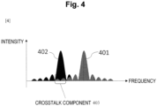
- the pulse train in the case where M is 1 is shown as 301 in Fig. 3 .
- scattered light only f 1 and f 3 are shown in 302, for ease of explanation.
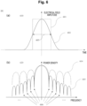
- the main signal components can be separated into 303 and 304 by signal processing. However, side lobes are present in the occupied band of a scattered light signal as illustrated in Fig. 4 .
- the side lobes of the scattered light generated by the light pulse of the optical frequency f 1 component cause crosstalk 403 into the main lobe of the scattered light generated by the light pulse of the optical frequency f 3 . Since the crosstalk 403 is present, the signal actually separated as the optical frequency component f 3 is formed with an overlap between the crosstalk component and the main signal component as shown in 305 in Fig. 3 , and these components cannot be separated from each other.
- a section in which a crosstalk component overlaps with a front portion of a main signal component is set as an overlap section 307, and a phase is calculated at a position 308 in the section 307.
- the distance from the incidence end of the position 308 is represented by l.
- the main signal component and the crosstalk component are combined in a vector state in a plane in which the abscissa axis represents the in-phase component and the ordinate axis represents the quadrature component, and form observation vectors.
- the value of the distance from the incidence end of the crosstalk component is represented by l', which differs from l. This is because the crosstalk component and the main signal component are received at different timings, and accordingly, with the vector corresponding to the position 308 of the main signal component, the vector corresponding to the different position 309 of the crosstalk component overlaps. As illustrated in a positional relationship 310 in the fiber in Fig. 3 , the position 308 is located before the vibration position 306, while the position 309 is located behind the vibration position 306. As illustrated in Fig.
- the vector of the main signal component does not change, since the position 308 is a point located before the vibration position 306. Meanwhile, since the position 309 is located behind the vibration position 306, a change is caused in the angle of the crosstalk component by vibration. As a result, the observation vector also changes in angle. Given that the angle of the observation vector r 3 (l, T) is represented by ⁇ 3 (l, T), for example, the amount of change in the angle is expressed by Expression (1-6). [Math. 1-6] ⁇ 3 l , T ′ ⁇ ⁇ 3 l T
- the amount of change expressed by Expression (1-6) depends not only on the magnitude of the vibration generated at the vibration position 306 but also on the lengths of the vector of the main signal component and the vector of the crosstalk component and on the angular difference between the two vectors. Since the length and the angle of a vector change from position to position due to a fading effect, the amount of change in the angle shown in Expression (1-6) changes in response to the distance l. For example, the same applies to the angle change at a position that is behind the position 308 by ⁇ l, as long as the position is within the overlap section 307.
- crosstalk of the optical frequency f 1 into the optical frequency f 3 is taken into consideration in the above example, crosstalk by some other optical frequency also exists. Also, the above example has clarified that vibration is observed at a spot other than the actual vibration spot with respect to the time of sampling at the optical frequency f 3 due to the influence of crosstalk of another optical frequency into the optical frequency f 3 . However, the same holds true for the time of sampling at another optical frequency. Further, although an example where M is 1 has been described, the same argument holds true in an example where M is another appropriate number.
- vibration is often observed at a spot that is not a vibration spot.
- the influence of this is conspicuous particularly in a situation where the use of pulses of short durations to increase the spatial resolution widen the band occupied by each optical frequency component in the frequency domain, a state where it is necessary to multiplex a very large number of optical frequency components in a limited frequency band, and the like.
- the problem of vibration, resulting from crosstalk, being observed at a spot that is not a vibration spot has been mentioned.
- the main signal component and the crosstalk component are combined in a vector state in a plane in which the abscissa axis represents the in-phase component and the ordinate axis represents the quadrature component, and form observation vectors.
- the abscissa axis represents the in-phase component
- the ordinate axis represents the quadrature component
- This embodiment suggests a method for solving the problem of the crosstalk by the pulse shape of each optical frequency component having an outer shape that changes smoothly.
- the temporal waveform of each optical frequency pulse that is used in this suggestion is illustrated in 610 in Fig. 6 .
- the outline of the envelope of an electrical field before multiplication by the carrier frequency is shown.
- a waveform 601 is a conventional rectangular wave shape that is also used in Non Patent Literature 5, and a waveform 602 indicates a waveform shape that is used in the present disclosure.
- Waveform shapes are not limited to a specific shape, as long as crosstalk can be prevented.
- a raised cosine waveform can be used.
- the waveform 602 is illustrated as a raised cosine waveform, for example.
- the full width at half maximum 603 of the pulse is made the same as that of a rectangular wave, so that the spatial resolution of the vibration measurement device can be kept constant, and degradation of the SN ratio of a signal can also be prevented.
- the power density in the frequency domain is shown in 620.
- the pulse train where the raised cosine waveform is used has an outer shape 701 illustrated in Fig. 7 . With the use of the pulse train illustrated in 701, the vector length with the crosstalk component can be shortened.
- a modulation signal 802 is given to an SSB modulator 801 to modulate continuous light and create a light pulse pair 803.
- the modulation signal 802 to be given is designed so that the envelope of each modulation frequency component has an outer shape of a raised cosine waveform, the magnitude of the electrical field of each optical frequency component can also have an outer shape that changes smoothly.
- the generated pulse pair 803 can be regarded approximately as a pulse pair in which optical frequencies are in a sequence of f 0 +f 1 , f 0 +f 2 , and f 0 +f 3 .
- the center frequencies of bandpass filters for extracting the respective optical frequency components in the signal processing unit 17c are only required to be set as f 1 , f 2 , and f 3 .
- the measurement resolution can also be set on the assumption that the full width at half maximum (FWHM) of the raised cosine waveform, which is the envelope of each modulation frequency component of the modulation signal 802, approximately matches the FWHM of each optical frequency component of the magnitude of the electrical field of the pulse pair 803.
- FWHM full width at half maximum
- the passband width of a bandpass filter in the signal processing unit 17c is determined by the FWHM of the raised cosine waveform.
- the resolution can also be determined through adjustment of the FWHM of the raised cosine waveform, with the characteristics of an SSB being taken into consideration.
- the selection is performed so that the center of the main lobe of the main optical frequency included in one of the pulse pairs is located at the position of the valley of the side lobe of each main optical frequency included in another illustrated in 606 in Fig. 6 .
- the influence of crosstalk resulting from the side lobes can be made smaller.
- light pulse pairs that can be used in the present disclosure are not limited to those having the configuration illustrated in Fig. 2 , but can be used for all techniques for improving a sampling rate through frequency multiplexing.
- a waveform having small spectral side lobes such as a raised cosine waveform instead of a conventional rectangular wave, is used as the pulse outer shape of each optical frequency component.
- crosstalk between different optical frequency components is reduced, erroneous detection of vibration at spots other than the vibration spot is prevented, the occurrence of a phenomenon in which the vibrational waveform at the vibration spot is distorted compared with the actual vibrational waveform is reduced, and the influence that hinders complete correction of the angular difference using a compensation optical frequency is made smaller.
- the present disclosure can be applied to information and communication industries.
Landscapes
- Physics & Mathematics (AREA)
- General Physics & Mathematics (AREA)
- Measurement Of Mechanical Vibrations Or Ultrasonic Waves (AREA)
- Photometry And Measurement Of Optical Pulse Characteristics (AREA)
Applications Claiming Priority (1)
| Application Number | Priority Date | Filing Date | Title |
|---|---|---|---|
| PCT/JP2021/021991 WO2022259437A1 (fr) | 2021-06-09 | 2021-06-09 | Dispositif et procédé de mesure de vibrations |
Publications (2)
| Publication Number | Publication Date |
|---|---|
| EP4354100A1 true EP4354100A1 (fr) | 2024-04-17 |
| EP4354100A4 EP4354100A4 (fr) | 2025-03-12 |
Family
ID=84425962
Family Applications (1)
| Application Number | Title | Priority Date | Filing Date |
|---|---|---|---|
| EP21945113.5A Pending EP4354100A4 (fr) | 2021-06-09 | 2021-06-09 | Dispositif et procédé de mesure de vibrations |
Country Status (5)
| Country | Link |
|---|---|
| US (1) | US20240280403A1 (fr) |
| EP (1) | EP4354100A4 (fr) |
| JP (1) | JP7639912B2 (fr) |
| CN (1) | CN117480364A (fr) |
| WO (1) | WO2022259437A1 (fr) |
Families Citing this family (3)
| Publication number | Priority date | Publication date | Assignee | Title |
|---|---|---|---|---|
| US20230283385A1 (en) * | 2022-02-18 | 2023-09-07 | Nec Laboratories America, Inc | Data transmission-tolerant distributed acoustic sensing using chirped-pulses with time-domain roll off |
| CN118155350A (zh) * | 2023-12-11 | 2024-06-07 | 云南保利天同水下装备科技有限公司 | 分区探测方法、分区探测系统及其防御探测组件 |
| CN120521644B (zh) * | 2025-07-28 | 2025-10-10 | 四川复津安科技有限责任公司 | 一种光纤多参量传感系统及其工作方法 |
Family Cites Families (5)
| Publication number | Priority date | Publication date | Assignee | Title |
|---|---|---|---|---|
| JP5849056B2 (ja) * | 2013-02-18 | 2016-01-27 | 日本電信電話株式会社 | 光パルス試験装置及び光パルス試験方法 |
| JP5753882B2 (ja) | 2013-10-04 | 2015-07-22 | 日本電信電話株式会社 | 光パルス試験装置とその試験光パルス送信ユニット及び光パルス試験方法 |
| JP7016013B2 (ja) | 2019-02-05 | 2022-02-04 | 日本電信電話株式会社 | 振動検出方法、信号処理装置及びプログラム |
| JP7111045B2 (ja) | 2019-04-03 | 2022-08-02 | 日本電信電話株式会社 | 位相測定方法及び信号処理装置 |
| WO2021075015A1 (fr) * | 2019-10-17 | 2021-04-22 | 日本電信電話株式会社 | Procédé et dispositif de test d'impulsion optique |
-
2021
- 2021-06-09 US US18/567,606 patent/US20240280403A1/en active Pending
- 2021-06-09 WO PCT/JP2021/021991 patent/WO2022259437A1/fr not_active Ceased
- 2021-06-09 EP EP21945113.5A patent/EP4354100A4/fr active Pending
- 2021-06-09 JP JP2023526737A patent/JP7639912B2/ja active Active
- 2021-06-09 CN CN202180098778.9A patent/CN117480364A/zh active Pending
Also Published As
| Publication number | Publication date |
|---|---|
| WO2022259437A1 (fr) | 2022-12-15 |
| CN117480364A (zh) | 2024-01-30 |
| JPWO2022259437A1 (fr) | 2022-12-15 |
| EP4354100A4 (fr) | 2025-03-12 |
| US20240280403A1 (en) | 2024-08-22 |
| JP7639912B2 (ja) | 2025-03-05 |
Similar Documents
| Publication | Publication Date | Title |
|---|---|---|
| EP3951334B1 (fr) | Procédé de mesure de phase et dispositif de traitement de signal | |
| CN114543973B (zh) | 一种分布式超高频振动信号测量方法及光纤传感器 | |
| EP4354100A1 (fr) | Dispositif et procédé de mesure de vibrations | |
| JP6893137B2 (ja) | 光ファイバ振動検知センサおよびその方法 | |
| EP4047333B1 (fr) | Procédé et dispositif de test d'impulsion optique | |
| JP7435160B2 (ja) | 光ファイバ振動検知装置及び振動検知方法 | |
| EP3922964B1 (fr) | Procédé de détection de vibration, dispositif de traitement de signal et programme | |
| US11522606B2 (en) | Phase measurement method, signal processing device, and program | |
| CN108873007A (zh) | 一种抑制振动效应的调频连续波激光测距装置 | |
| EP4354099B1 (fr) | Dispositif de traitement de signal, système de détection de vibration et procédé de traitement de signal | |
| JP7435772B2 (ja) | 歪変化計測装置及び歪変化計測方法 | |
| US20260104285A1 (en) | Signal processing method in phase otdr | |
| US20250003789A1 (en) | Optical pulse test method and optical pulse test equipment | |
| US12270688B2 (en) | Optical fiber sensor and Brillouin frequency shift measurement method | |
| EP4296624B1 (fr) | Procédé de traitement de signal et dispositif de traitement de signal |
Legal Events
| Date | Code | Title | Description |
|---|---|---|---|
| STAA | Information on the status of an ep patent application or granted ep patent |
Free format text: STATUS: THE INTERNATIONAL PUBLICATION HAS BEEN MADE |
|
| PUAI | Public reference made under article 153(3) epc to a published international application that has entered the european phase |
Free format text: ORIGINAL CODE: 0009012 |
|
| STAA | Information on the status of an ep patent application or granted ep patent |
Free format text: STATUS: REQUEST FOR EXAMINATION WAS MADE |
|
| 17P | Request for examination filed |
Effective date: 20231120 |
|
| AK | Designated contracting states |
Kind code of ref document: A1 Designated state(s): AL AT BE BG CH CY CZ DE DK EE ES FI FR GB GR HR HU IE IS IT LI LT LU LV MC MK MT NL NO PL PT RO RS SE SI SK SM TR |
|
| DAV | Request for validation of the european patent (deleted) | ||
| DAX | Request for extension of the european patent (deleted) | ||
| A4 | Supplementary search report drawn up and despatched |
Effective date: 20250205 |
|
| RIC1 | Information provided on ipc code assigned before grant |
Ipc: G01D 5/353 20060101ALI20250131BHEP Ipc: G01H 9/00 20060101AFI20250131BHEP |
|
| RAP3 | Party data changed (applicant data changed or rights of an application transferred) |
Owner name: NTT, INC. |
|
| STAA | Information on the status of an ep patent application or granted ep patent |
Free format text: STATUS: EXAMINATION IS IN PROGRESS |
|
| 17Q | First examination report despatched |
Effective date: 20251002 |
|
| GRAP | Despatch of communication of intention to grant a patent |
Free format text: ORIGINAL CODE: EPIDOSNIGR1 |
|
| STAA | Information on the status of an ep patent application or granted ep patent |
Free format text: STATUS: GRANT OF PATENT IS INTENDED |