EP4354111A1 - Appareil et procédé pour incorporer un échantillon histologique dans un matériau d'incorporation - Google Patents
Appareil et procédé pour incorporer un échantillon histologique dans un matériau d'incorporation Download PDFInfo
- Publication number
- EP4354111A1 EP4354111A1 EP23202089.1A EP23202089A EP4354111A1 EP 4354111 A1 EP4354111 A1 EP 4354111A1 EP 23202089 A EP23202089 A EP 23202089A EP 4354111 A1 EP4354111 A1 EP 4354111A1
- Authority
- EP
- European Patent Office
- Prior art keywords
- heated
- dispensing
- container
- embedding material
- hopper
- Prior art date
- Legal status (The legal status is an assumption and is not a legal conclusion. Google has not performed a legal analysis and makes no representation as to the accuracy of the status listed.)
- Pending
Links
Images


Classifications
-
- G—PHYSICS
- G01—MEASURING; TESTING
- G01N—INVESTIGATING OR ANALYSING MATERIALS BY DETERMINING THEIR CHEMICAL OR PHYSICAL PROPERTIES
- G01N1/00—Sampling; Preparing specimens for investigation
- G01N1/28—Preparing specimens for investigation including physical details of (bio-)chemical methods covered elsewhere, e.g. G01N33/50, C12Q
- G01N1/30—Staining; Impregnating ; Fixation; Dehydration; Multistep processes for preparing samples of tissue, cell or nucleic acid material and the like for analysis
- G01N1/31—Apparatus therefor
-
- G—PHYSICS
- G01—MEASURING; TESTING
- G01N—INVESTIGATING OR ANALYSING MATERIALS BY DETERMINING THEIR CHEMICAL OR PHYSICAL PROPERTIES
- G01N1/00—Sampling; Preparing specimens for investigation
- G01N1/28—Preparing specimens for investigation including physical details of (bio-)chemical methods covered elsewhere, e.g. G01N33/50, C12Q
- G01N1/36—Embedding or analogous mounting of samples
-
- G—PHYSICS
- G01—MEASURING; TESTING
- G01N—INVESTIGATING OR ANALYSING MATERIALS BY DETERMINING THEIR CHEMICAL OR PHYSICAL PROPERTIES
- G01N1/00—Sampling; Preparing specimens for investigation
- G01N1/28—Preparing specimens for investigation including physical details of (bio-)chemical methods covered elsewhere, e.g. G01N33/50, C12Q
- G01N1/44—Sample treatment involving radiation, e.g. heat
-
- G—PHYSICS
- G01—MEASURING; TESTING
- G01N—INVESTIGATING OR ANALYSING MATERIALS BY DETERMINING THEIR CHEMICAL OR PHYSICAL PROPERTIES
- G01N1/00—Sampling; Preparing specimens for investigation
- G01N1/28—Preparing specimens for investigation including physical details of (bio-)chemical methods covered elsewhere, e.g. G01N33/50, C12Q
- G01N1/36—Embedding or analogous mounting of samples
- G01N2001/366—Moulds; Demoulding
Definitions
- the present invention generally concerns an apparatus and process for processing a histological sample in the embedding step. More particularly, the present invention relates to a dispensing system of embedding material arranged to dispense different layers of embedding material in the liquid state.
- the embedding step of a histological tissue in an embedding material is performed after a surgical sample taken from a patient has undergone cutting ("grossing"), formalin fixation and a treatment ("processing") in which the tissue sample is dehydrated in alcohol and then clarified with xylene, so as to transform the tissue itself from hydrophilic to hydrophobic, in order to proceed with a first impregnation in paraffin.
- an embedding material typically paraffin
- Document JP6383625B2 describes a system to automatically perform the embedding operation of a histological sample in an embedding material.
- the biological tissue is inserted into a histology cassette, within which it is while it undergoes the aforementioned processing operation, to be then directed towards the subsequent embedding step.
- a histology cassette is illustrated in Figure 1A of the annexed drawings.
- the number 1 indicates the assembly of a cassette 2 and a lid 3.
- the body of the cassette 2 made of plastic material, is in the form of a relatively flat container, with a flat bottom wall 4 and two pairs of opposite walls defining a containment cavity for the histological sample, which can be closed with the lid 3.
- the bottom wall 4 of the cassette 2 is shaped like a grid, for reasons that will become clear in the following.
- an operator separates the lid 3 of the cassette 2, takes the histological sample from the cassette 2 with the aid of a clamp and places it on the bottom of a mould intended to receive the embedding material, and eventually already arranged with a first layer of embedding material (typically paraffin at a temperature sufficient to keep it in a fluid state).
- the mould can be constituted, for example, of plastic or metallic material and can have a bottom of dimensions which vary according to the sample to be received.
- FIG 1B of the annexed drawings illustrates some examples of moulds 5 of a conventional type.
- the moulds 5 are configured and sized to receive the body of a cassette 2 above them. Indeed, after the histological sample has been positioned on the bottom of a mould 5, the cassette 2 (separated from the lid 3) is applied on top of the mould 5, forming a containment group G as illustrated in Figure 1C . Still with reference to Figure 1B , it can be seen that, although the external dimensions of each mould 5 are chosen in such a way as to allow the application of the body of the cassette over the mould, each mould 5 has a bottom cavity 6, intended to receive the histological sample, which varies in size from mould to mould, depending on the histological sample to be received.
- the operator pours a first layer of embedding material on the bottom 6 of a mould 5 and then inserts the histological sample taken from a cassette on the bottom 6 of the mould 5.
- This step is extremely critical to ensure a high reliability of the examination that is subsequently performed on the sample.
- the operator must pay attention to place the histological sample on the bottom of the mould with the most appropriate orientation in order to guarantee the best results in the next microtomy step, in which the sample embedded in a block of embedding material is subjected to the cut.
- the operator places the mould 5 containing the histological sample, with the cassette 2 applied above it, under a dispensing tap of embedding material (typically paraffin) maintained at a temperature sufficient to leave it in a fluid state.
- embedding material typically paraffin
- the embedding material is poured by gravity into the mould 5, making it pass through openings of the bottom wall 4 of the cassette 2. Fluid is poured in sufficient quantity to fill the mould and the containment space of the cassette above the mould.
- the mould 5 Once the mould 5 has been filled with embedding material, it must be subjected to cooling to solidify the embedding material. At that point, the solidified body of the embedding material, with the histological sample embedded therein, is separated from the mould 5 for further manipulation. The body of the cassette 2 remains joined to the solidified body.
- a typically adopted solution involves a heated tank into which the solid embedding material is poured in grains, to be melted thanks to the heat generated in the tank.
- the heated tank has a considerable capacity, for example on the order of 2 liters, so that it can receive a considerable volume of embedding material which is then liquefied within the tank.
- the embedding material in the liquid state is then used in small doses through a dispensing tap, doses on the order of about 6 grams for each containment group G.
- the initialization time of the process is particularly long, as it is necessary to melt a large quantity of solid material before starting with dispensing.
- the object of the present invention is to solve the above-mentioned drawbacks.
- a further object of the invention is to achieve all of the above purposes with relatively simple and low-cost means.
- the invention relates to an apparatus for processing a histological sample to be embedded in an embedding material, comprising a dispensing system of embedding material arranged to dispense different layers of embedding material in the liquid state, wherein said dispensing system comprises:
- the present invention relates to an apparatus for embedding a histological sample in an embedding material, comprising a dispensing system 8 of embedding material, arranged to dispense different layers of embedding material in the liquid state.
- the different layers of liquid material can be dispensed in a containment group G (set of a mould 5 and cassette 2) according to respective steps of a process for embedding a histological sample in the embedding material. More specifically, a first layer of embedding material (typically paraffin) is dispensed at the bottom of a respective mould 5, after the histological sample has been placed at the bottom of the mould 5 (e.g. by means of an operator).
- a first layer of embedding material typically paraffin
- a cassette 2 is placed over the mould 5, in order to obtain a containment group G as shown in Figure 1C .
- a second layer of embedding material is dispensed on the containment group G (formed by mould 5 and cassette 2) as explained in more detail below.
- the apparatus is fully automated so that the histological sample and the embedding material can be processed without manual operations performed by an operator.
- Figure 2 shows the part of the apparatus related only to the dispensing system 8.
- the dispensing system 8 is intended to be integrated within an automation system that can work continuously to carry out various processing operations on embedding material, before and after the dispensing step of layers of embedding material.
- the apparatus may comprise a bench on which an input area is defined that is configured to receive from a transport system cassettes 2 containing histological samples.
- Automated transport systems are provided upstream and downstream of the apparatus.
- the transport system which is arranged upstream feeds cassettes 2 containing histological samples to be analyzed, while the transport system downstream of the apparatus feeds histological samples, each embedded in a body of embedding material, to the next station of an automated sample processing line.
- such systems are made according to what is described in the Italian patent application No. 102021000009788 by the same Applicant.
- transport systems are not described here, both as they can be made in any known way, and as they, taken alone, do not fall within the scope of the present invention. It should be noted that the upstream and downstream transport systems, in a less preferable and not illustrated embodiment, can also be manual.
- the apparatus includes an electronic controller E (shown only schematically in Figure 2 ).
- the electronic controller E is configured and programmed to control the automated devices of the apparatus, including the dispensing system 8, and to possibly assist an operator working in a working area.
- the apparatus further comprises a manipulator device of any known type, arranged to pick up the cassettes received in the input area and to lay them, if necessary, in an accumulation area provided with a system to maintain the cassettes in an illustrated temperature range.
- the manipulator device can be a robot of any known type preferably having a movable head along three mutually orthogonal axes X, Y, Z.
- the working area where there may be an operator, receives only one cassette at a time sequentially. Only when the cycle of operations to be performed in the working area on a particular cassette 2 is over, the system enables the feeding to the working area of a new cassette.
- the electronic controller E controls the manipulator device to pick up a given cassette from the accumulation area and feed it to the working area.
- the electronic controller E can be configured and programmed to perform a selection ("sorting") of the cassette to be picked up.
- an operator manually performs the necessary operations to arrange a histological sample within a respective mould 5, orienting it appropriately.
- the operator picks up the sample and lays it on the bottom of a respective mould 5 after having preliminarily poured on the bottom of the mould 5 a first layer of embedding material (typically paraffin) through a dispensing station.
- the operator applies the cassette 2 over the mould 5 and places the resulting group G on a transfer device to transport the group towards a further step in the process.
- Figure 1C of the attached drawings shows the result of the above operations.
- Each containment group G comprises a mould 5 on whose bottom 6 there is the first layer of embedding material dispensed by the dispensing station, in which the operator has placed and then oriented the histological sample.
- the body of the cassette 2 is applied over the mould 5 as a lid.
- the mould 5 and the body of the cassette 2 have dimensions suitable for this purpose.
- the body of the cassette 2 defines a cavity 2B intended to be filled with liquid embedding material, whose bottom wall 4 has through openings, in order to allow the passage of the embedding material that is poured through the cavity 2B within the mould 5 below.
- the inclined end surface 2A of the body of the cassette 2 remains in a position exposed to view.
- the cassette 2 comprises an information carrier C, which may be a code of any known type (such as a bar code) but in the example is a QR code. Even the mould may include its own information carrier F. Due to these features, it is achieved in the process and apparatus according to the invention the advantage of continuous traceability of each processed sample, which allows to associate the sample with identifying information related to it during the whole course of operations performed in the apparatus.
- an information carrier C which may be a code of any known type (such as a bar code) but in the example is a QR code.
- the mould may include its own information carrier F. Due to these features, it is achieved in the process and apparatus according to the invention the advantage of continuous traceability of each processed sample, which allows to associate the sample with identifying information related to it during the whole course of operations performed in the apparatus.
- the transfer device brings the mould 5 containing the histological sample with the body of the cassette 2 applied over it to near the dispensing system 8.
- the following description shows the peculiar features of the dispensing system 8 of embedding material, arranged to dispense the above-mentioned layers of embedding material in the liquid state.
- the liquid material is dispensed after a melting step of solid state material introduced at the beginning of the process.
- the dispensing system 8 comprises a containment tank 9 configured to receive solid grains of embedding material, later to be melted.
- the containment tank 9 is only arranged to contain and convey the solid grains of embedding material towards a lower portion of the system 8, downstream of the tank 9, which allows to melt and dispense the embedding material in an automated manner.
- the tank 9 comprises an upper opening 10 for inserting the grains.
- the grains are conveyed by gravity within the tank 9, towards the aforementioned lower portion of system 8.
- the tank 9 is not provided with heating means to heat its volume, as it is only arranged to convey the solid grains later to be melted.
- the dispensing system 8 comprises at least one hopper 11 operatively connected to the containment tank 9, at a lower end thereof opposite to the upper opening 10.
- the hopper 11 is configured to gradually convey the previously poured solid material into the containment tank 9.
- Each hopper 11 comprises a screw conveyor 12 arranged on a bottom portion of the hopper 11, and transversely extended with respect to the vertical spacing of the tank 9 and the hopper 11.
- the screw conveyor 12 is controlled in rotation by a respective motor 13, in order to convey the solid grains to a further step of the process.
- the dispensing system 8 comprises two hoppers 11 operating in parallel and both connected to the containment tank 9.
- the dispensing system 8 has a total capacity of a grain quantity of about 3.5 kg, while each hopper 11 can contain about 600 g of embedding material.
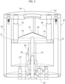
- FIG 3 illustrates a section view of a part of the system 8, specifically of hoppers 11.
- reference 14 shows a plurality of photocell sensors to verify the level of remaining grains in the hoppers 11.
- each hopper 11 has a photocell sensor 14 on each side, so that two pairs of sensors 14 are made.
- Each pair of sensors 14 is configured to verify the level of remaining grains in the respective hopper 11.
- the electronic controller E receives a signal to be transmitted to an operator, i.e. by means of a human-machine interface device, which communicates the need to refill the upper containment tank 9 with grains of embedding material (paraffin).
- the operating principle of the hopper 11 is to drop limited quantities of solid grains down to a heated lower portion of the system 8, so that the same quantity of liquid material available for dispensing is maintained at all times, with the minimum thermal shock.
- the hopper 11 does not provide any heating means to melt the material received from the tank 9.
- the dispensing system 8 comprises at least one heated container 15 operatively connected to the hopper 11 by means of at least one connection duct 16.
- the heated container 15 is configured to receive the material conveyed from the hopper 11 and to melt the gradually received embedding material.
- the containment tank 9, the hopper 11 and the heated container 15 are then cascaded together, so that limited quantities of embedding material are gradually melted in the heated container 15, with respect to the total quantity introduced in the containment tank 9.
- the heated container 15 comprises heating means to constantly maintain the container 15 at a temperature between about 65° C and 75° C, so as to prevent the embedding material from solidifying along the way to the final dispensing. It should be noted that the aforementioned upper temperature limit is due to the fact that the histological samples degrade at a temperature above 75° C.
- the heated container 15 has a smaller volume than that of the containment tank 9 and the hopper 11, and more specifically the volume of the container 15 is equal to or less than 5-10% of the sum of the volumes of the tank 9 and the hopper 11.
- the heated container 15 is a container of cylindrical shape defining a side wall 15', an upper wall 15" and a bottom wall 15′′′.
- the upper wall 15" has a central opening 16' connected to an end portion of the connection duct 16, to receive the solid grains from the hopper 11.
- the heated container 15 is a container operating as a boiler, arranged to melt the solid material coming from the hopper 11, making the liquid material available for final dispensing.
- the dispensing system 8 also comprises a dispensing device 17 connected to the heated container 15, to dispense the previously melted liquid material within the heated container 15. Details of the dispensing device 17 and the dispensing step are given later in this description.
- the dispensing system 8 comprises two parallel heated containers 15, each connected to a respective hopper 11 in communication with the containment tank 9.
- each heated container 15 comprises a respective dispensing device 17, so as to parallelize the dispensing of different layers of embedding material.
- the dispensing system 8 comprises a single heated container 15 to which two dispensing devices 17 are connected, still to parallelize the dispensing of different layers of embedding material.
- FIG 4 shows a section view of the heated container 15 and the dispensing device 17.
- the heated area 18 comprises a heated surface 19 arranged to receive by gravity the solid material from the upper opening 16', and to melt the material thus deposited on the surface 19.
- the heated area 18 is spaced within the container 15 at an intermediate height between the top wall 15" and the bottom wall 15"', with a base circumference of slightly smaller diameter than that of the container 15.
- the heated area 18 is supported at the aforementioned intermediate height by a support rod 20 vertically extended within the container 15 from the bottom wall 15′′′.
- the heated area 18 and the support rod 20 form an umbrella-like configuration, since the support rod 20 bears the heated area 18 which has an extension substantially covering the volume of container 15 below the heated area 18, preventing the direct fall of the material from the upper opening 16' towards the bottom wall 15'".
- the heated container 15 there is a peripheral free space 21 obtained between the inner surface of the side wall 15' of the heated container 15 and the perimeter of the heated area 18.
- a free space 21 is obtained with the function of letting flow the material melted by the heated area 18, towards the bottom wall 15′′′ of the heated container 15.
- the heated surface 19 has an inclined shape so as to direct the liquid material from a central area of the heated surface 19, towards the peripheral free space 21.
- the heated surface 19 has a conical shape with two sides sloping in opposite directions, joined at a central upper vertex 22.
- the heated surface 19 may have a shape of the spherical cap type.
- the free space 21 between the base circumference of the heated area 18 and the inner surface of the side wall 15' of the container 15 is in the order of 1 mm. This size allows liquid paraffin to flow, but also allows impurities to be retained, so that the umbrella structure also acts as a filter to retain impurities.
- the heated container 15 comprises heating means to reach the temperature necessary to melt the solid grains received through the upper opening 16'.
- Figure 5 illustrates further features of the container 15, also in this regard.
- Reference 23 indicates an axial housing included within the support rod 20 to include a first heating resistance able to heat the heated surface 19 on which the solid material settles.
- Reference 24 indicates a further housing extended below the bottom wall 15'", to include a second heating resistance able to heat the structure of the container 15.
- References 25, 26 indicate respective vertical channels obtained between the upper wall 15" of the heated container 15 and the heated surface 19, respectively arranged to house a temperature sensor (to measure the temperature reached within the container 15) and a vent duct for the passage of air. It should be noted that the aforementioned temperature sensor is useful for constantly monitoring the reached temperature, so as to ensure a correct process free from anomalies due to incorrect temperature ranges.
- the dispensing system 8 includes a dispensing device 17 to dispense the previously melted liquid material within the heated container 15.
- the dispensing device 17 is operatively connected to the heated container 15 by means of a dispensing duct 27.
- the dispensing duct 27 has a proximal portion 27' connected to a bottom opening 28 obtained on the bottom wall 15′′′ of the heated container 15. Consequently, the liquid material fallen by gravity on the bottom wall 15'", through the aforementioned peripheral free space 21, is made flow within the duct 27 through the bottom opening 28.
- the dispensing duct 27 also comprises a distal portion 27" connected to the dispensing device 17.
- Reference 29 indicates a level sensor for measuring the level of liquid material deposited on the bottom of the container 15. The sensor is operatively connected to the electronic controller E to transmit a signal related to the level of accumulated liquid material, so as to consequently control the operation of the hopper 11.
- the dispensing device 17 comprises an automatic adjustment device for automatically adjusting the outflow of liquid material.
- the adjustment device comprises a solenoid valve 30 and a dispensing tap 31.
- the tap 31 is controlled by the solenoid valve 30 which is controlled by the electronic controller E on the basis of a feedback signal sent by a sensor associated to the dispensing device 17.
- the sensor is able to detect the level of the embedding material, and can be an optical sensor of any known type, for example operating in reflection, able to measure the distance of the sensor itself with respect to the free surface of the fluid of embedding material poured into the group G or the mould 5.
- the signal emitted by the sensor can also be displayed on a monitor in the form of a numerical indication of the distance between the sensor and the free surface of the embedding material.
- the distance progressively decreases until a predetermined value is reached, corresponding to the correct quantity of embedding material, which is predetermined according to the size of the cassette 2 and the mould 5 arranged below the cassette 2.
- the electronic controller E is therefore able to close the solenoid valve 30 which controls the dispensing of embedding material and consequently stop the dispensing of the material upon reaching a correct quantity.
- the electronic controller E during this dispensing operation takes into account, through a specific algorithm, the information already previously possessed on the volume occupied by the histological sample within the mould 5, as well as on the size of the bottom of the mould 5 itself, in order to adequately calibrate the dispensing of the appropriate quantity of embedding material to reach the aforementioned predetermined level.
- Figure 6 shows a section view of the connection portion between the dispensing device 17 and the end part of the heated container 15.
- References 32, 33 respectively indicate a housing for a temperature sensor, to measure the temperature reached in the dispensing duct 27, and a housing for a further heating resistance, to heat the duct 27 so as to prevent the paraffin from solidifying along the way towards the dispensing tap 31.
- the dispensing of the embedding material is carried out in a controlled and precise manner, as the system 8 includes a sensor able to detect the level of embedding material within the mould 5 or the group G, assisted by an algorithm able to calibrate the dispensing on the basis of a series of parameters known to the electronic controller E.
- the moulds 5 are located in a position below the dispensing tap 31 ( Figure 2 ), to receive a flow of embedding material, which is therefore at a temperature useful to keep it in a fluid state.
- two dispensing devices 17 can be connected to a single heated container to parallelize the dispensing of different layers of embedding material.
- the present invention provides for the melting of limited quantities of embedding material necessary for the continuous production of a limited number of paraffin blocks, avoiding the melting at the same time of large quantities which are then used within a period of one or more days depending on laboratory requests. All this results in avoiding possible problems of paraffin denaturation, i.e. chemical alterations of paraffin due to the preservation of paraffin at high temperatures for an extended time.
- the apparatus can further comprise a cooling system arranged to cool the containment groups G each containing the histological sample and the embedding material in the liquid state, previously dispensed by means of the dispensing system 8.
- the apparatus can further comprise a device for the detachment of the solidified material from the respective cooled mould.
- a transport device can provide for feeding the solidified material including the histological sample to the output or to an accumulation area.
- the apparatus comprises an automatic output transport system to feed the moulds, from which the embedding material in the solid state has been detached, through a cleaning station to remove the residues of the embedding material and then convey them back to a feeding system of the moulds in the working area.
Landscapes
- Life Sciences & Earth Sciences (AREA)
- Health & Medical Sciences (AREA)
- General Health & Medical Sciences (AREA)
- Chemical & Material Sciences (AREA)
- Analytical Chemistry (AREA)
- Biochemistry (AREA)
- Physics & Mathematics (AREA)
- General Physics & Mathematics (AREA)
- Immunology (AREA)
- Pathology (AREA)
- Engineering & Computer Science (AREA)
- Biomedical Technology (AREA)
- Molecular Biology (AREA)
- Sampling And Sample Adjustment (AREA)
Applications Claiming Priority (1)
| Application Number | Priority Date | Filing Date | Title |
|---|---|---|---|
| IT202200021159 | 2022-10-13 |
Publications (1)
| Publication Number | Publication Date |
|---|---|
| EP4354111A1 true EP4354111A1 (fr) | 2024-04-17 |
Family
ID=84943598
Family Applications (1)
| Application Number | Title | Priority Date | Filing Date |
|---|---|---|---|
| EP23202089.1A Pending EP4354111A1 (fr) | 2022-10-13 | 2023-10-06 | Appareil et procédé pour incorporer un échantillon histologique dans un matériau d'incorporation |
Country Status (3)
| Country | Link |
|---|---|
| US (1) | US20240125679A1 (fr) |
| EP (1) | EP4354111A1 (fr) |
| CN (1) | CN117890188A (fr) |
Families Citing this family (1)
| Publication number | Priority date | Publication date | Assignee | Title |
|---|---|---|---|---|
| USD1065581S1 (en) * | 2022-09-19 | 2025-03-04 | Parhelia Biosciences Corporation | Support tile for histologic device for biological samples |
Citations (5)
| Publication number | Priority date | Publication date | Assignee | Title |
|---|---|---|---|---|
| CN205175773U (zh) * | 2015-11-19 | 2016-04-20 | 天津爱华医疗器械有限公司 | 一种生物组织包埋机 |
| US20170241712A1 (en) * | 2016-02-18 | 2017-08-24 | Leica Biosystems Nussloch Gmbh | Melting apparatus for metered melting of paraffin |
| EP3220125A1 (fr) * | 2016-03-15 | 2017-09-20 | Leica Microsystems Ltd. Shanghai | Distributeur de paraffine, dispositif d'insertion et procédé de commande et appareil de commande de distributeur de paraffine |
| JP6383625B2 (ja) | 2014-10-03 | 2018-08-29 | サクラ精機株式会社 | 包埋装置 |
| CN213792266U (zh) * | 2020-08-03 | 2021-07-27 | 河北鑫达钢铁集团有限公司 | 一种通用型h型钢静电喷蜡装置 |
Family Cites Families (4)
| Publication number | Priority date | Publication date | Assignee | Title |
|---|---|---|---|---|
| DE10006084B4 (de) * | 2000-02-11 | 2009-01-02 | Leica Biosystems Nussloch Gmbh | Färbeautomat mit einer Heizstation |
| US6441348B1 (en) * | 2001-01-10 | 2002-08-27 | Raymond Industrial Limited | Heat treatment apparatus and method of using same |
| US7871058B2 (en) * | 2007-07-25 | 2011-01-18 | Illinois Tool Works Inc. | Dual inline solenoid-actuated hot melt adhesive dispensing valve assembly |
| WO2019036760A1 (fr) * | 2017-08-22 | 2019-02-28 | Leica Biosystems Melbourne Pty Ltd | Améliorations dans le traitement des spécimens de tissus histologiques |
-
2023
- 2023-10-06 EP EP23202089.1A patent/EP4354111A1/fr active Pending
- 2023-10-12 US US18/485,611 patent/US20240125679A1/en active Pending
- 2023-10-13 CN CN202311326265.6A patent/CN117890188A/zh active Pending
Patent Citations (5)
| Publication number | Priority date | Publication date | Assignee | Title |
|---|---|---|---|---|
| JP6383625B2 (ja) | 2014-10-03 | 2018-08-29 | サクラ精機株式会社 | 包埋装置 |
| CN205175773U (zh) * | 2015-11-19 | 2016-04-20 | 天津爱华医疗器械有限公司 | 一种生物组织包埋机 |
| US20170241712A1 (en) * | 2016-02-18 | 2017-08-24 | Leica Biosystems Nussloch Gmbh | Melting apparatus for metered melting of paraffin |
| EP3220125A1 (fr) * | 2016-03-15 | 2017-09-20 | Leica Microsystems Ltd. Shanghai | Distributeur de paraffine, dispositif d'insertion et procédé de commande et appareil de commande de distributeur de paraffine |
| CN213792266U (zh) * | 2020-08-03 | 2021-07-27 | 河北鑫达钢铁集团有限公司 | 一种通用型h型钢静电喷蜡装置 |
Also Published As
| Publication number | Publication date |
|---|---|
| US20240125679A1 (en) | 2024-04-18 |
| CN117890188A (zh) | 2024-04-16 |
Similar Documents
| Publication | Publication Date | Title |
|---|---|---|
| EP2322938B1 (fr) | Appareil et procédés de gestion et intégration automatiques d'échantillons de tissus | |
| EP4354111A1 (fr) | Appareil et procédé pour incorporer un échantillon histologique dans un matériau d'incorporation | |
| US12545875B2 (en) | System for handling sensitive products, in particular packaging system | |
| CN103827649B (zh) | 用于确定容器产品的预定特性存在的方法和实施该方法的设备 | |
| CN110382399B (zh) | 用于储存和分配容器的单元和方法以及灌装设备 | |
| EP4348217B1 (fr) | Poste de travail automatisé, et procédé, pour la manipulation d'échantillons histologiques dans l'étape d'enrobage | |
| CN114111149A (zh) | 可运输容器、充装机系统、方法和套件 | |
| US8640557B2 (en) | Automatic analysis of finely divided solids | |
| EP1431436A2 (fr) | Machine de teinture des matières textiles | |
| WO2024047502A1 (fr) | Appareil et procédé de refroidissement de plusieurs groupes de confinement, renfermant chacun un échantillon histologique et un matériau d'enrobage à l'état liquide | |
| US12290016B2 (en) | System and method for automating propagation material sampling and propagation material sampling equipment | |
| CA2800136C (fr) | Cassette pour un appareil de traitement automatise et integration des echantillons de tissus | |
| BR102020022386A2 (pt) | Sistema e processo de automação de amostragem de material de propagação e equipamento de amostragem de material de propagação | |
| HK1194463A (en) | Method for establishing the presence of specified characteristics of a container product and device for performing said method | |
| HK1194463B (en) | Method for establishing the presence of specified characteristics of a container product and device for performing said method |
Legal Events
| Date | Code | Title | Description |
|---|---|---|---|
| PUAI | Public reference made under article 153(3) epc to a published international application that has entered the european phase |
Free format text: ORIGINAL CODE: 0009012 |
|
| STAA | Information on the status of an ep patent application or granted ep patent |
Free format text: STATUS: THE APPLICATION HAS BEEN PUBLISHED |
|
| AK | Designated contracting states |
Kind code of ref document: A1 Designated state(s): AL AT BE BG CH CY CZ DE DK EE ES FI FR GB GR HR HU IE IS IT LI LT LU LV MC ME MK MT NL NO PL PT RO RS SE SI SK SM TR |
|
| STAA | Information on the status of an ep patent application or granted ep patent |
Free format text: STATUS: REQUEST FOR EXAMINATION WAS MADE |
|
| 17P | Request for examination filed |
Effective date: 20241004 |
|
| RBV | Designated contracting states (corrected) |
Designated state(s): AL AT BE BG CH CY CZ DE DK EE ES FI FR GB GR HR HU IE IS IT LI LT LU LV MC ME MK MT NL NO PL PT RO RS SE SI SK SM TR |
|
| GRAP | Despatch of communication of intention to grant a patent |
Free format text: ORIGINAL CODE: EPIDOSNIGR1 |
|
| STAA | Information on the status of an ep patent application or granted ep patent |
Free format text: STATUS: GRANT OF PATENT IS INTENDED |