EP4354113A1 - Verfahren zur beurteilung der physikalischen eigenschaften von lebensmitteln - Google Patents
Verfahren zur beurteilung der physikalischen eigenschaften von lebensmitteln Download PDFInfo
- Publication number
- EP4354113A1 EP4354113A1 EP22811435.1A EP22811435A EP4354113A1 EP 4354113 A1 EP4354113 A1 EP 4354113A1 EP 22811435 A EP22811435 A EP 22811435A EP 4354113 A1 EP4354113 A1 EP 4354113A1
- Authority
- EP
- European Patent Office
- Prior art keywords
- plunger
- food
- physical property
- upper plunger
- property evaluation
- Prior art date
- Legal status (The legal status is an assumption and is not a legal conclusion. Google has not performed a legal analysis and makes no representation as to the accuracy of the status listed.)
- Granted
Links
Images


Classifications
-
- G—PHYSICS
- G01—MEASURING; TESTING
- G01N—INVESTIGATING OR ANALYSING MATERIALS BY DETERMINING THEIR CHEMICAL OR PHYSICAL PROPERTIES
- G01N33/00—Investigating or analysing materials by specific methods not covered by groups G01N1/00 - G01N31/00
- G01N33/02—Food
-
- G—PHYSICS
- G01—MEASURING; TESTING
- G01N—INVESTIGATING OR ANALYSING MATERIALS BY DETERMINING THEIR CHEMICAL OR PHYSICAL PROPERTIES
- G01N3/00—Investigating strength properties of solid materials by application of mechanical stress
- G01N3/32—Investigating strength properties of solid materials by application of mechanical stress by applying repeated or pulsating forces
- G01N3/34—Investigating strength properties of solid materials by application of mechanical stress by applying repeated or pulsating forces generated by mechanical means, e.g. hammer blows
-
- G—PHYSICS
- G01—MEASURING; TESTING
- G01N—INVESTIGATING OR ANALYSING MATERIALS BY DETERMINING THEIR CHEMICAL OR PHYSICAL PROPERTIES
- G01N11/00—Investigating flow properties of materials, e.g. viscosity, plasticity; Analysing materials by determining flow properties
- G01N11/10—Investigating flow properties of materials, e.g. viscosity, plasticity; Analysing materials by determining flow properties by moving a body within the material
- G01N11/14—Investigating flow properties of materials, e.g. viscosity, plasticity; Analysing materials by determining flow properties by moving a body within the material by using rotary bodies, e.g. vane
Definitions
- the present invention relates to a food physical property evaluation method.
- NPL 1 discloses a research report based on thermal analysis for "melt in mouth" of a chocolate.
- a melting behavior alone of oil or fat is measured, and a change in food properties due to an emulsifying effect with saliva which occurs in a mouth, or the like is not taken into consideration.
- PTL 1 discloses a mastication simulation device including a container and a pair of simulative mastication teeth facing each other in the container.
- PTL 2 discloses a bolus forming device including artificial teeth and an artificial tongue provided in an artificial oral cavity.
- NPL 1 Satoko Shiotsubo, "Application of Thermal Analysis to Food (Part 1)", Cookery Science, 1991, 24.1: 54-61 .
- an evaluation result of the food texture obtained by the measurement in the related art does not coincide with an evaluation result of the food texture (sensory evaluation) obtained by actual eating.
- One factor is that while the perception of food texture during eating involving a continuous change in food properties from the moment the food enters mouth until it is swallowed, the measurement in the related art are conducted using methods that do not take into consideration the changes in the food properties within the oral cavity.
- the chocolate melts at a body temperature, receives a vertical stress and a shear stress due to contact with a tongue and an oral mucous membrane, and is emulsified by being mixed with saliva at the same time. These events occur continuously from the vicinity of a chocolate surface, and finally the whole is swallowed in a melted and emulsified state. Therefore, in order to evaluate the food texture of the chocolate by measurement, it is considered necessary to take into account the changes in the food properties according to the above-described continuous events.
- an object of the invention is to provide a food physical property evaluation method in which a change in food properties in an oral cavity can be simulated and a physical quantity corresponding to perception in the oral cavity can be obtained.
- a food physical property evaluation method includes: placing a food to be evaluated on a lower occlusal part of a lower plunger which has a shape to occlude with an upper occlusal part of an upper plunger and is provided to face the upper occlusal part of the upper plunger; causing at least one of the upper plunger and the lower plunger to perform a reciprocating linear movement in a linear direction in which the upper plunger and the lower plunger are occluded and separated, causing at least one of the upper plunger and the lower plunger to perform a reciprocating rotation movement in a rotation direction with the linear direction as a rotation axis, and adjusting a pressure applied between the upper plunger and the lower plunger by a method other than pneumatics; and measuring a physical quantity including a force and a torque applied to the upper plunger or the lower plunger, and evaluating food physical properties based on the obtained physical quantity.
- a change in food properties in an oral cavity can be simulated, a physical quantity corresponding to perception in the oral cavity can be obtained, and food physical properties can be evaluated.
- FIG. 1 is a schematic view showing a configuration of a food physical property evaluation device 1 according to the embodiment.
- the food physical property evaluation device 1 includes an upper plunger 10, a lower plunger 20, a sensor 12, a drive unit 30, and a measurement control unit 40.
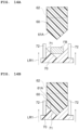
- FIG. 2 is a schematic view showing a configuration of the upper plunger 10 and the lower plunger 20 of the food physical property evaluation device 1 in FIG. 1 .
- the upper plunger 10 and the lower plunger 20 are intraoral models having shapes suitable for evaluation of physical properties of a chocolate, and the food physical property evaluation device 1 according to the embodiment can be suitably used particularly for the evaluation of the physical properties of the chocolate.
- the upper plunger 10 is provided with an upper occlusal part 11.
- the upper occlusal part 11 of the upper plunger 10 has, for example, a hemispherical convex portion at a tip end thereof.
- the lower plunger 20 is provided such that a lower occlusal part 21 having a shape to be occluded with the upper occlusal part 11 faces the upper occlusal part 11.
- the lower occlusal part 21 has a concave portion to be occluded with the upper occlusal part 11.
- the concave portion has a shape having a hemispherical surface as an inner wall surface.
- the upper plunger 10 and the lower plunger 20 are made of a resin having a hardness suitable for forming the intraoral model, for example, an acrylonitrile-butadienestyrene copolymer (ABS) resin, an acrylic resin, or a fluorine-containing resin such as polyvinylidene fluoride.
- ABS acrylonitrile-butadienestyrene copolymer
- acrylic resin acrylic resin
- fluorine-containing resin such as polyvinylidene fluoride
- a sensor 12 is incorporated in the upper plunger 10, and measures a physical quantity applied to the upper plunger 10.
- the sensor 12 may be embedded in the upper plunger 10.
- the sensor 12 is, for example, a six-axis sensor.
- the physical quantity measured by the six-axis sensor includes, for example, a force and a torque applied to the upper plunger 10.
- the drive unit 30 includes, for example, a motor.
- the drive unit 30 drives the lower plunger 20 such that the lower plunger 20 performs a reciprocating linear movement LR in a linear direction to occlude with and separated from the upper plunger 10.
- the drive unit 30 drives the upper plunger 10 such that the upper plunger 10 performs a reciprocating rotation movement RR in a rotation direction with the linear direction of the reciprocating linear movement LR of the lower plunger 20 as a rotation axis AX.
- the food physical property evaluation device 1 includes a pressure adjustment unit that adjusts a pressure applied between the upper plunger 10 and the lower plunger 20 by a method other than pneumatics when the upper occlusal part 11 of the upper plunger 10 and the lower occlusal part 21 of the lower plunger 20 come into contact with each other during occlusion.
- the pressure adjustment unit includes a solid elastic body such as a motor or a spring, and adjusts the pressure applied between the upper plunger 10 and the lower plunger 20 by power of the motor or an elastic force of the solid elastic body.
- the drive unit 30 may be driven by the motor. By using the motor, it is possible to adjust the pressure more easily and with higher accuracy than in the case of using the pneumatics in which hysteresis (a history effect) is large, and it is possible to model a mastication movement.
- the measurement control unit 40 controls the reciprocating linear movement LR of the lower plunger 20 and the reciprocating rotation movement RR of the upper plunger 10 by the drive unit 30.
- the measurement control unit 40 measures the physical quantity applied to the upper plunger 10 based on an output of the sensor 12.
- the measurement control unit 40 can obtain impulse data by integrating measured force data over time.
- the food physical property evaluation device 1 drives the lower plunger 20 to perform the reciprocating linear movement LR by placing a food FA to be evaluated on the lower occlusal part 21, and evaluates physical properties of the food FA based on a physical quantity (a measured value) obtained from the output of the sensor 12 when the upper plunger 10 is driven to perform the reciprocating rotation movement RR.
- the upper plunger 10 and the lower plunger 20 are disposed at positions where the upper plunger 10 and the lower plunger 20 are not in contact with each other even when the upper plunger 10 and the lower plunger 20 are closest to each other.
- a force corresponding to a set compression force is applied from the lower plunger 20 to the food FA, and is further applied to the upper plunger 10 via the food FA.
- a force exceeding the set compression force is not applied.
- a cylindrical protective part 22 is provided on an outer circumference of the lower plunger 20.
- the protective part 22 prevents the food FA from jumping out from a space between the upper plunger 10 and the lower plunger 20.
- the food physical property evaluation device 1 further includes, for example, an artificial saliva supply unit 50 that adds artificial saliva at a predetermined flow rate and causes the artificial saliva to flow between the upper plunger 10 and the lower plunger 20.
- An inflow tube 51 extends from the artificial saliva supply unit 50 to the space between the upper plunger 10 and the lower plunger 20 through the protective part 22. Only one inflow tube 51 is provided in FIG. 1 , and a plurality of inflow tubes 51 may be provided.
- the artificial saliva is added at the predetermined flow rate and flows between the upper plunger 10 and the lower plunger 20.
- As the artificial saliva for example, a 0.02% aqueous solution of xanthan gum whose flow characteristics are approximated to that of saliva can be used.
- an aqueous solution containing sodium hydrogen carbonate, potassium dihydrogen phosphate trihydrate, sodium chloride, potassium chloride, calcium chloride dihydrate and mucin and adjusted to pH 6.95 with hydrochloric acid can be used.
- an aqueous solution obtained by adding amylase to these substances may be used.
- a portion including at least the upper plunger 10 and the lower plunger 20 is adjustable to a predetermined temperature.
- the predetermined temperature is, for example, a temperature near the body temperature.
- the portion including the upper plunger 10 and the lower plunger 20 may be the whole food physical property evaluation device 1.
- the temperature can be adjusted using, for example, a warm air device.
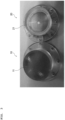
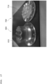
- FIG. 3 is a photograph showing an example of the upper plunger 10 and the lower plunger 20 of the food physical property evaluation device 1 in FIG. 1 .
- the upper plunger 10 is provided with the upper occlusal part 11 having a hemispherical convex portion at a tip end thereof.
- the lower plunger 20 is provided with the lower occlusal part 21 having a concave shape having a hemispherical surface as an inner wall surface to occlude with the upper occlusal part 11.
- the food physical property evaluation method according to the embodiment is performed by using the food physical property evaluation device 1 according to the embodiment.
- the food physical property evaluation device 1 includes the upper plunger 10 provided with the upper occlusal part 11, the lower plunger 20 provided such that the lower occlusal part 21 having a shape to be occluded with the upper occlusal part 11 faces the upper occlusal part 11, and the sensor 12 that is incorporated in the upper plunger 10 and that measures a physical quantity applied to the upper plunger 10.
- the food FA to be evaluated is placed on the lower occlusal part 21 having such a configuration.
- the drive unit 30 drives the lower plunger 20 to perform the reciprocating linear movement LR in a direction in which the lower plunger 20 is to be occluded with the upper plunger 10, and drives the upper plunger 10 such that the upper plunger 10 performs the reciprocating rotation movement RR with a direction of the reciprocating linear movement LR of the lower plunger 20 as the rotation axis AX.
- the drive unit 30 adjusts the pressure applied between the upper plunger 10 and the lower plunger 20.
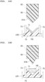
- FIG. 4A is a schematic view showing operations of the upper plunger 10 and the lower plunger 20 of the food physical property evaluation device 1 in FIG. 1 .
- the food FA to be evaluated such as a chocolate is placed on the lower occlusal part 21 of the lower plunger 20.
- the lower plunger 20 is elevated in a first linear movement direction LR1, and the lower occlusal part 21 of the lower plunger 20 occludes with the upper occlusal part 11 of the upper plunger 10.
- the lower plunger 20 is elevated in the first linear movement direction LR1, and the lower occlusal part 21 of the lower plunger 20 occludes with the upper occlusal part 11 of the upper plunger 10.
- the upper plunger 10 is rotated in a second rotation movement direction RR2 to cause the upper occlusal part 11 of the upper plunger 10 to slide while being in contact with the food FA.
- FIGS. 4A to 4D a step in which the lower plunger 20 is elevated from a lowermost position, occludes with the upper plunger 10, and then lowers again to return to the lowermost position is also referred to as one compression.
- the reciprocating linear movement LR of the lower plunger 20 and the reciprocating rotation movement RR of the upper plunger 10 are performed, and at the same time, the physical quantity is measured based on the output of the sensor 12.
- the physical properties of the food FA are evaluated based on the obtained physical quantity.
- items such as a compression force (a maximum force applied to the food), a compression frequency (a number of occlusion per unit time: an occlusion frequency), an artificial saliva addition flow rate, a number of compression (an number of occlusion), and a temperature can be set.
- an appearance of a bolus during compression and after a predetermined number of times of compression can be visually checked, and the bolus can also be subjected to another physical property measurement.
- a force acting on the upper plunger 10 during occlusion and a torque acting on the upper plunger 10 due to rotational sliding between the upper plunger 10 and the lower plunger 20 are measured.
- the measurement control unit 40 integrates the measured force data over time to obtain the impulse data.
- a temporal change in the physical quantity for example, a temporal change in a force (an impulse obtained when integrated), and a temporal change in a torque are obtained.
- the operations of the upper plunger 10 and the lower plunger 20 of the food physical property evaluation device 1 according to the embodiment described above simulate a sliding behavior of a tongue in an oral cavity.
- the food physical property evaluation device 1 in the embodiment it is possible to simulate the sliding behavior of the tongue to reproduce the change in the food properties in the oral cavity, and to obtain a physical quantity corresponding to perception in the oral cavity.
- a force an impulse obtained when integrated
- a torque are obtained for the food to be evaluated.
- a temporal change in the force (the impulse obtained when integrated) and a temporal change in the torque are obtained with respect to the food to be evaluated.
- the food physical properties can be evaluated based on these pieces of data.
- an intraoral model that simulates the sliding behavior of the tongue is not known.
- the food physical property evaluation device 1 by simulating the sliding behavior of the tongue, reproducibility of the change in the food properties in the oral cavity can be enhanced, and the physical quantity corresponding to the perception in the oral cavity can be obtained.
- the food physical property evaluation device 1 by measuring the torque applied to the upper plunger 10 or the lower plunger 20, it is possible to obtain the physical quantity corresponding to a feeling of the sliding behavior of the tongue.
- the reciprocating linear movement is performed in a vertical direction, an actual movement in the oral cavity can be more accurately modeled.
- the food physical property evaluation device 1 In the food physical property evaluation device 1 according to the first embodiment, about 2.5 g of a commercially available chocolate sample was used, and a test was conducted in which the upper plunger 10 and the lower plunger 20 were driven in the operations shown in FIGS. 4A to 4D .
- the treatment was performed for 120 seconds (the number of compression is 120 times) under conditions of a compression interval of 1 time/second, a compression force of 200 N, and an angular velocity of 180°/s (reversing the rotation direction at each compression interval).
- a temperature of a plunger surface in contact with the chocolate was adjusted to 36.5°C to 37.0°C.
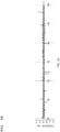
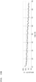
- FIG. 5A is a graph showing an example of the force data obtained by the food physical property evaluation device 1 in FIG. 1 .
- FIG. 5A is a graph in which one peak appears in one compression.
- an impulse value for each compression can be calculated.
- An impulse change profile during the test can be determined from a moving average of the impulses for every ten compressions.
- FIG. 5B is a graph showing an example of the torque data obtained by the food physical property evaluation device 1 in FIG. 1 . Since rotation in the first rotation movement direction RR1 and rotation in the second rotation movement direction RR2 are alternately performed for each compression, the torques form a graph in which positive peaks and negative peaks alternately appear.
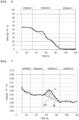
- FIG. 6 is a graph showing a temporal change in the impulse obtained by the food physical property evaluation device 1 in FIG. 1 .
- the impulse value is calculated, and a profile of the temporal change in the impulse during the test is further obtained from the moving average of the impulses for every ten compressions.
- a time domain can be divided into three parts, that is, a domain 1 in which the impulse is substantially constant (a slope is substantially zero); a domain 2 in which the impulse decreases (the slope is negative and is substantially constant); and a domain 3 in which the impulse is substantially unchanged (the slope is substantially zero).
- a regression line in which the slope is substantially zero or the slope is negative and constant is shown.
- the three domains of the profile of the temporal change in the impulse are estimated to correspond to stages of changes in properties of the chocolate, and can be described as follows.
- the domain 1 is a period when heat and a force are applied and surroundings are wet, but cutting, melting, and emulsification do not occur, or occur only locally.
- the domain 2 is a period when the cutting, the melting, and the emulsification begin to occur and overall "melting" occurs.
- the domain 3 is a period when the chocolate is completely melted and emulsified.
- the entire profile of the temporal change in the impulse and feature data on each domain can be used as indices for physical property evaluation.
- Examples of the feature data on the entire profile of the temporal change in the impulse that can be the indices for the physical property evaluation include a maximum value, a minimum value, an average value, and a standard deviation.
- Examples of the feature data on the domain 1, the domain 2, and the domain 3 that can be the indices for the physical property evaluation include a maximum value, a minimum value, an average value, a slope of the regression line, and a domain time.
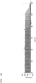
- FIG. 7 is a graph showing a temporal change in an absolute value of the torque obtained by the food physical property evaluation device 1 in FIG. 1 .
- a profile of the temporal change in the torque during the test is obtained from a moving average of the torques for every ten compressions.
- the time domain can be divided into four domains, that is, a domain 1 in which the torque decreases (the slope is substantially constant), a domain 2 in which the torque substantially does not change (the slope is substantially zero), a domain 3 in which the torque increases and reaches a peak and then decreases (the slope is positive and reaches a peak and then becomes negative), and a domain 4 in which the torque substantially does not change (the slope is substantially zero).
- the four domains of the profile of the temporal change in the torque are estimated to correspond to stages of changes in properties of the chocolate, and can be described as follows.
- the domain 1 is a period when heat and a force are applied and surroundings are wet, but cutting, melting, and emulsification do not occur, or occur only locally.
- the domain 2 is a period when the cutting, the melting, and the emulsification begin to occur but only to a limited extent, and an increase in a contact area between the upper plunger 10 and lower plunger 20 is small.
- the domain 3 is a period when the contact area between the upper plunger 10 and the lower plunger 20 increases due to the cutting and the melting and thickening occurs due to mixing of the melted chocolate and a moisture, and subsequently, a resistance starts to decrease due to a progress of the melting and the emulsification.
- the domain 4 is a period when the chocolate is completely melted and emulsified. The domain 4 may not appear depending on the conditions of the test.
- the entire profile of the temporal change in the torque and feature data on each domain can be used as indices for physical property evaluation.
- Examples of the feature data on the entire profile of the temporal change in the torque that can be the indices for the physical property evaluation include a maximum value, a minimum value, an average value, and a standard deviation.
- Examples of the feature data on the domain 1, the domain 2, and the domain 4 that can be the indices for the physical property evaluation include a maximum value, a minimum value, an average value, a slope of the regression line, and a domain time.
- Examples of the feature data on the domain 3 that can be the indices for the physical property evaluation include a maximum value, a minimum value, an average value, a slope of the regression line where the slope up to the peak is positive, a slope of the regression line where the slope is negative after the peak, a peak time, a height H of the peak from a baseline BL, and an integral value AP of the peak (an area of the domain between peak and the baseline BL).
- the baseline BL is a straight line connecting a start point and an end point of the peak.
- a test the same as that in the first example was performed on two types of commercially available chocolates (a chocolate CA and a chocolate CB, and each sample is about 2.5 g). During the test, a force and a torque applied to the upper plunger 10 by the sensor 12 were measured.
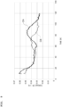
- FIG. 8 is a graph showing a temporal change in the impulse obtained for two types of chocolates (the chocolate CA and the chocolate CB).
- FIG. 9 is a graph showing a temporal change in an absolute value of the torque obtained for two types of chocolates (the chocolate CA and the chocolate CB). A profile of the temporal change in the torque during the test was obtained from a moving average of the torques for every ten compressions.
- FIG. 10 is a graph showing a food texture sensory evaluation result. Scores are shown for each item of the "melting speed”, the “sticky feeling”, the “ease of spread in mouth”, and the “state in mouth after swallowing” for two types of chocolates (the chocolate CA and the chocolate CB). According to the food texture sensory evaluation result, compared to the chocolate CA, the chocolate CB melts faster, has no sticky feeling, spreads easily in the mouth, and results in a dry state in mouth after swallowing.
- the above-described food texture sensory evaluation result can be estimated by associating the feature data on the profile of the temporal change in the impulse in FIG. 8 and the profile of the temporal change in the torque in FIG. 9 with each other as follows.
- FIG. 11 is a graph showing a physical property measurement result according to the second example.
- the "melting speed” has a negative correlation with the domain 1 of the impulse.
- the “sticky feeling” has a positive correlation with a peak height in the domain 3 of the torque, or a positive correlation with a peak time. It is considered that the chocolate changes from an oil continuous phase to a water continuous phase just before swallowing, and a consistency increases during the phase change and the chocolate becomes sticky.
- the "ease of spread in mouth” has a negative correlation with a peak height in the domain 3 of the torque or a negative correlation with a peak time.
- the “state in mouth after swallowing” has a negative correlation with an average value of the impulses in the domain 3.
- a food physical property evaluation device has a configuration the same as that of the food physical property evaluation device 1 according to the first embodiment except that an upper plunger 60 and a lower plunger 70 have the following configurations.
- the upper plunger 60 and the lower plunger 70 according to the embodiment are intraoral models having shapes suitable for evaluation of physical properties of a chocolate snack, and the food physical property evaluation device according to the embodiment can be suitably used particularly for evaluation of the physical properties of a chocolate snack.
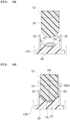
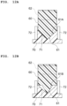
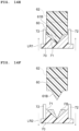
- FIG. 12A is a schematic view showing a configuration of the food physical property evaluation device according to the embodiment in a state in which the upper plunger 60 and the lower plunger 70 are occluded when viewed from one direction.
- An upper occlusal part 61 is provided at a tip end of the upper plunger 60.
- the upper occlusal part 61 has a shape in which convex portions and concave portions are alternately disposed in a circumferential direction, and for example, four convex portions and four concave portions therebetween are alternately disposed in the circumferential direction.
- FIG. 12A shows a shape of a first convex portion 61A, which is one of the four convex portions.
- the lower plunger 70 is provided such that a lower occlusal part 71 having a shape to be occluded with the upper occlusal part 61 faces the upper occlusal part 61.
- the lower occlusal part 71 has a shape provided with a convex-concave shape corresponding to a position to be occluded with a concave-convex shape of the upper occlusal part 61.
- FIG. 12B is a schematic view showing a configuration of the food physical property evaluation device in FIG. 12A in the state in which the upper plunger 60 and the lower plunger 70 are occluded when viewed from another direction orthogonal to the one direction.
- FIG. 12A shows a shape of a second convex portion 61B, which is one of the four convex portions.
- the second convex portion 61B is a convex portion whose tip end is sharper than the first convex portion 61A.
- the upper occlusal part 61 of the upper plunger 60 in the embodiment has a shape in which the first convex portion 61A and the second convex portion 61B are alternately disposed in the circumferential direction. That is, the first convex portion 61A extending in one direction and the second convex portion 61B extending in a direction orthogonal to the one direction intersect in a cross shape.
- the lower occlusal part 71 of the lower plunger 70 has a shape in which concave portions and convex portions are alternately disposed in the circumferential direction, which coincides with or is close to the shape of the first convex portion 61A that is more obtuse than the second convex portion 61B.
- a sensor 62 is incorporated in the upper plunger 60, and measures a physical quantity applied to the upper plunger 60.
- a cylindrical protective part 72 is provided on an outer circumference of the lower plunger 70.
- the lower plunger 70 having the above configuration is provided so as to be capable of reciprocating linear movement in the linear direction in which the lower plunger 70 is to be occluded with the upper plunger 60 as in the first embodiment, and the upper plunger 60 is provided so as to be capable of reciprocating rotation movement with a direction of the reciprocating linear movement of the lower plunger 70 as a rotation axis.
- the upper occlusal part 61 of the upper plunger 60 can be occluded most deeply at a position at which the upper occlusal part 61 can be occluded with the lower occlusal part 71, that is, in an arrangement in which positions of most protruding tip ends of the convex portions of the upper plunger 60 and positions of most concave portions of the concave portions of the lower plunger 70 coincide with each other.
- the lower plunger 70 may be occluded with the upper plunger 60 at a position shifted in the circumferential direction from the arrangement in which the positions of the most protruding tip ends of the convex portions of the upper plunger 60 and the positions of the most concave portion of the concave portions of the lower plunger 70 coincide with each other. Operations of the upper plunger 60 in this case will be described later.
- FIG. 13 is a photograph showing an example of the upper plunger 60 and the lower plunger 70 of the food physical property evaluation device according to the embodiment.
- the upper plunger 60 is provided with the upper occlusal part 61 including the first convex portions 61A and the second convex portions 61B.
- the lower plunger 70 is provided with the lower occlusal part 71 having a concave-convex shape to be occluded with the upper occlusal part 61.
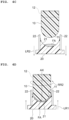
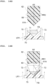
- FIG. 14A is a schematic view of an example of operations of the upper plunger 60 and the lower plunger 70 of the food physical property evaluation device in FIG. 12A when viewed from the one direction.
- a food FB to be evaluated is placed on the lower occlusal part 71.
- the lower plunger 70 is elevated in the first linear movement direction LR1, and the lower occlusal part 71 of the lower plunger 70 occludes with the upper occlusal part 61 of the upper plunger 60.
- the lower plunger 70 is lowered in the second linear movement direction LR2, and the occlusion between the lower occlusal part 71 of the lower plunger 70 and the upper occlusal part 61 of the upper plunger 60 is released. Since the surfaces of the first convex portions 61A and the concave-convex-shaped surface of the lower occlusal part 71 are occluded with no or almost no gap therebetween, the food FB is crushed to have a uniform thickness.
- FIG. 14D is a schematic view of an example of the operations of the upper plunger 60 and the lower plunger 70 of the food physical property evaluation device in FIG. 12A as viewed from the other direction orthogonal to the one direction.
- the food FB to be evaluated is placed on the lower occlusal part 71, the lower plunger 70 is elevated in the first linear movement direction LR1, and the lower occlusal part 71 of the lower plunger 70 occludes with the upper occlusal part 61 of the upper plunger 60.
- the lower plunger 70 is lowered in the second linear movement direction LR2, and the occlusion between the lower occlusal part 71 of the lower plunger 70 and the upper occlusal part 61 of the upper plunger 60 is released. Since the surfaces of the second convex portions 61B and the concave-convex-shaped surface of the lower occlusal part 71 are occluded with a gap therebetween, the food FB is cut at the center.
- FIG. 14G is a schematic view of an example of the operations of the upper plunger 60 and the lower plunger 70 of the food physical property evaluation device in FIG. 12A when viewed from the one direction.
- the food FB to be evaluated is placed on the lower occlusal part 71.
- the lower plunger 70 is elevated in the first linear movement direction LR1, and the lower occlusal part 71 of the lower plunger 70 occludes with the upper occlusal part 61 of the upper plunger 60.
- the upper plunger 60 rotates in the second rotation movement direction RR2 (or the first rotation movement direction RR1), and the lower plunger 70 is occluded with the upper plunger 60 at a position shifted in the circumferential direction from the arrangement in which the positions of the most protruding tip ends of the convex portions of the upper plunger 60 and the positions of the most concave portions of the concave portions of the lower plunger 70 coincide with each other.
- the tip ends of the convex portions (the first convex portion 61A or the second convex portion 61B) of the upper occlusal part 61 are in contact with inclined surfaces constituting the concave portions and the convex portions of the lower occlusal part 71.
- the tip ends of the convex portions of the upper occlusal part 61 are slid on the inclined surfaces while rotating the upper plunger 60 in the first rotation movement direction RR1, and the tip ends of the convex portions of the upper occlusal part 61 may be slid on the inclined surfaces while rotating in the second rotation movement direction RR2.
- a direction in which the tip ends of the convex portions of the upper occlusal part 61 slide on the inclined surfaces constituting the concave portions and the convex portions of the lower occlusal part 71 is a direction in which the positions of the most protruding tip ends of the convex portions of the upper occlusal part 61 and the positions of the most concave portions of the concave portions of the lower occlusal part 71 coincide with each other.
- a configuration may be adopted in which the sliding of the tip ends of the convex portions of the upper occlusal part 61 on the inclined surfaces is performed on at least a part of the inclined surfaces.
- the sliding may be performed until the positions of the most protruding tip ends of the convex portions of the upper occlusal part 61 and the positions of the most concave portions of the concave portions of the lower occlusal part 71 coincide with each other.
- the upper plunger 60 and the lower plunger 70 are disposed at positions where the upper plunger 60 and the lower plunger 70 are not in contact with each other even when the upper plunger 60 and the lower plunger 70 are closest to each other in an arrangement in which the positions of the tip ends of the convex portions of the upper occlusal part 61 and the positions of the most concave portions of the concave portions of the lower occlusal part 71 coincide with each other.
- a force corresponding to a set compression force is applied from the lower plunger 70 to the food FB, and is further applied to the upper plunger 60 via the food FB.
- a force exceeding the set compression force is not applied.
- the tip ends of the convex portions (the first convex portions 61A or the second convex portions 61B) of the upper occlusal part 61 can come into contact with the inclined surfaces constituting the concave portions and the convex portions of the lower occlusal part 71.
- FIGS. 14G to 14J are included. Only the operations of FIGS. 14G to 14J may be repeated. At this time, an angle of the upper plunger 60 under the arrangement in which the positions of the convex portions of the upper plunger 60 and the positions of the concave portions of the lower plunger 70 coincide with each other may be rotated by 90° each time one or more compression steps are completed.
- the upper plunger 60 is rotated by 90° each time one or more compression steps are completed, and an angle at which the upper occlusal part 61 is in contact with the food FB during the occlusion can be changed.
- the operations of FIGS. 14G to 14J may be performed for one or more compression steps.
- the operations of FIGS. 14A to 14C may be performed for one or more compression steps.
- one or more compression steps of the operations of FIGS. 14A to 14C may be alternately repeated.
- the operations of FIGS. 14A to 14C or FIGS. 14D to 14F as viewed from the orthogonal direction
- the operations of FIGS. 14G to 14J can be appropriately combined.
- a food suitable for evaluation of the food physical property evaluation device in the embodiment is a chocolate snack.
- the chocolate snack is, for example, a snack made of chocolate containing a puff.
- Various types of puffs can be used, and the puff is preferably a soybean puff, and more preferably a puff made by soybean protein.
- the soybean puff is obtained by puffing the soybean protein as a main ingredient, and the soybean protein is obtained by puffing a soybean protein concentrated ingredient.
- the operations of the upper plunger 60 and the lower plunger 70 of the food physical property evaluation device according to the embodiment shown in FIGS. 14G to 14J described above simulate a grinding behavior of teeth in an oral cavity.
- the food physical property evaluation device in the embodiment it is possible to simulate the grinding behavior of the teeth to simulate the change in the food properties in the oral cavity, and to obtain the physical quantity corresponding to perception in the oral cavity.
- a force an impulse obtained when integrated
- a torque are obtained for the food to be evaluated.
- a temporal change in the force (the impulse obtained when integrated) and a temporal change in the torque are obtained with respect to the food to be evaluated.
- the food physical properties can be evaluated based on these pieces of data.
- an intraoral model that continuously simulates a cutting behavior by the teeth and a grinding behavior of the teeth is not known.
- the food physical property evaluation device by continuously simulating the cutting behavior by the teeth and the grinding behavior of the teeth, reproducibility of the change in the food properties in the oral cavity can be enhanced, and the physical quantity corresponding to the perception in the oral cavity can be obtained.
- the food physical property evaluation device by measuring the torque applied to the upper plunger 60 or the lower plunger 70, it is possible to obtain the physical quantity corresponding to a feeling of the sliding behavior of the tongue.
- the reciprocating linear movement is performed in a vertical direction, an actual movement in the oral cavity can be more accurately modeled.
- FIG. 15A is a graph showing an example of force data obtained by the food physical property evaluation device in FIG. 12A .
- FIG. 15A is a graph in which one peak appears in one compression.
- an impulse value for each compression can be calculated.
- An impulse change profile during the test can be determined from a moving average of the impulses for every ten compressions.
- FIG. 15B is a graph showing an example of impulse data obtained by the food physical property evaluation device in FIG. 12A .
- a test the same as that in the third example was performed on two types of commercially available chocolate snacks (a chocolate snack CSA and a chocolate snack CSB, and each sample is about 8.0 g). During the test, a force applied to the upper plunger 60 by the sensor 62 was measured.
- the chocolate snack CSA and the chocolate snack CSB are both protein-rich chocolate snacks, and the chocolate snack CSA uses a flour ingredient as a main protein ingredient, and the chocolate snack CSB uses a soybean puff as the main protein ingredient.
- FIG. 16 is a graph showing a temporal change in the impulse obtained for two types of chocolate snacks (the chocolate snack CSA and the chocolate snack CSB).
- a soybean puff is a processed food containing a soybean protein as a main ingredient, and by using the soybean puff as a confectionery, it is possible to increase a protein content of a product and to impart a crispy and crunchy food texture. Since the chocolate snack CSB contains the soybean puff, it is considered that the impulse value at an early stage of mastication is large.
- the chocolate snack CSA is melted by mixing with saliva, whereas in the case of the chocolate snack CSB, it is considered that crispness and crunchiness is maintained to the end due to an effect of the soybean puff that is less likely to be melted even in the latter half of the mastication.
- FIG. 17 is a photograph showing an upper plunger 60X and a lower plunger 70X of a food physical property evaluation device according to a modification.
- a food suitable for evaluation executed by the food physical property evaluation device according to the modification is a gummy.
- the lower plunger 70X is provided with a lower occlusal part 71X having a shape in which a plurality of quadrangular pyramid-shaped convex portions are arranged side by side.
- the convex portions of the lower occlusal part 71X each have a quadrangular pyramid shape whose bottom surface is square with a side of 13 mm.
- the upper plunger 60X is provided with an upper occlusal part 61X having a concave-convex shape that is occluded with the plurality of convex portions of the lower occlusal part 71X.
- a food physical property evaluation method using the food physical property evaluation device according to the modification will be described.
- a gummy which is a food to be evaluated, is placed on the lower occlusal part 71X of the lower plunger 70X, and the lower plunger 70X is elevated to occlude the lower occlusal part 71X of the lower plunger 70X with the upper occlusal part 61X of the upper plunger 60X.
- the upper plunger 60X and the lower plunger 70X are occluded with each other at positions where the upper plunger 60X and the lower plunger 70X are not in contact with each other even when the upper plunger 60X and the lower plunger 70X are closest to each other.
- the gummy is pressed into a gap between the lower occlusal part 71X and the upper occlusal part 61X with a predetermined force.
- the lower plunger 70X is lowered, and the occlusion of the lower occlusal part 71X of the lower plunger 70X and the upper occlusal part 61X of the upper plunger 60X is released.
- the upper plunger 60X is rotated in a horizontal direction by 90 degrees until the upper plunger 60X and the lower plunger 70X reach positions where the upper plunger 60X and the lower plunger 70X are not in contact with each other even when the upper plunger 60X and the lower plunger 70X are closest to each other.
- the compression is performed a plurality of times.
- the 90-degree rotation in the horizontal direction of the upper plunger 60X performed for each compression is reversed, for example, every two times of the compression.
- a test the same as that in the third example was performed on one gummy of each of four types of commercially available gummy samples (a gummy GA, a gummy GB, a gummy GC, and a gummy GD).
- the treatment was performed with a compression frequency of 1 time/second, a compression force of 400 N, and a number of compression of 90 times.
- a temperature of a plunger surface in contact with the gummy was adjusted to 32.4°C ⁇ 1.5°C.
- 1 ml of artificial saliva was added in a device at the start, and was added at a flow rate of 4 ml/min during the test.
- a force applied to the upper plunger 60X by the sensor 62 was measured. From the start of the test until a two-point moving average of peak positions of the forces among outputs of the force was less than 320 N, impulses were calculated based on the outputs of the force, and a sum of the obtained impulses was calculated. The test was performed five times for each gummy, and an average value of values excluding a maximum value and a minimum value was obtained. An average value of the gummy GA was set to 5, and relative values with respect to the gummy GA were calculated for average values of the other gummies (the gummy GB, the gummy GC, and the gummy GD).
- Each of the four types of commercially available gummy samples described above was subjected to an intake test by ten subjects, and a total masseter muscle activity during intake of the gummy was determined. Ten subjects who were determined as being appropriate for the intake test in consideration of the oral environment and the like were selected from candidates who wished to perform the intake test.
- a physiological evaluation device described in a patent literature JP2012-139442A
- a muscle electrode was attached to the subject, and an electromyography of left and right masseter muscles from the start of mastication to swallowing of one gummy was acquired to determine the total masseter muscle activity.
- FIG. 18 is a graph showing the total masseter muscle activity (a relative value) with respect to the sum of the impulses (a relative value) obtained for the gummy GA, the gummy GB, the gummy GC, and the gummy GD. It was confirmed that the sum of the impulses (the relative value) and the total masseter muscle activity (the relative value) have a strong positive correlation with a correlation coefficient of 0.97.
- FIG. 19 is a graph showing the sum of impulses and the total masseter muscle activity (relative values) obtained for the gummy GA, the gummy GB, the gummy GC, and the gummy GD. It was confirmed that the relative value of the masseter muscle activity obtained from the intake test and the relative value of the sum of impulses obtained from the food physical property evaluation device according to the second embodiment are correlated regardless of hardness and type of the gummy, and that the food physical property evaluation device according to the modification of the second embodiment has validity as a device that simulates a mastication process.
- the lower plunger performs the reciprocating linear movement
- the upper plunger performs the reciprocating rotation movement
- the invention is not limited to the configuration. Configuration where at least one of the lower plunger and the upper plunger may perform the reciprocating linear movement, and at least one of the upper plunger and the lower plunger may perform the reciprocating rotation movement, may be applicable.
- the sensor may be incorporated in both the upper plunger and the lower plunger. The above embodiments can be applied to a device and a method of evaluating physical properties of a food other than a chocolate or a chocolate snack.
- a physical quantity measured by the sensor is not limited to a force (an impulse obtained by integrating from a force) and a torque, and can be applied to various physical quantities that can be detected by the upper plunger.
Landscapes
- Health & Medical Sciences (AREA)
- Life Sciences & Earth Sciences (AREA)
- Chemical & Material Sciences (AREA)
- Engineering & Computer Science (AREA)
- Food Science & Technology (AREA)
- General Health & Medical Sciences (AREA)
- Physics & Mathematics (AREA)
- General Physics & Mathematics (AREA)
- Immunology (AREA)
- Pathology (AREA)
- Biochemistry (AREA)
- Analytical Chemistry (AREA)
- Medicinal Chemistry (AREA)
- Investigating Strength Of Materials By Application Of Mechanical Stress (AREA)
- Dental Tools And Instruments Or Auxiliary Dental Instruments (AREA)
Applications Claiming Priority (2)
| Application Number | Priority Date | Filing Date | Title |
|---|---|---|---|
| JP2021090500 | 2021-05-28 | ||
| PCT/JP2022/021845 WO2022250167A1 (ja) | 2021-05-28 | 2022-05-27 | 食品物性の評価方法 |
Publications (4)
| Publication Number | Publication Date |
|---|---|
| EP4354113A1 true EP4354113A1 (de) | 2024-04-17 |
| EP4354113A4 EP4354113A4 (de) | 2025-06-18 |
| EP4354113C0 EP4354113C0 (de) | 2026-02-18 |
| EP4354113B1 EP4354113B1 (de) | 2026-02-18 |
Family
ID=84228977
Family Applications (1)
| Application Number | Title | Priority Date | Filing Date |
|---|---|---|---|
| EP22811435.1A Active EP4354113B1 (de) | 2021-05-28 | 2022-05-27 | Verfahren zur beurteilung der physikalischen eigenschaften von lebensmitteln |
Country Status (5)
| Country | Link |
|---|---|
| US (1) | US20240255484A1 (de) |
| EP (1) | EP4354113B1 (de) |
| JP (2) | JP2022183140A (de) |
| CN (1) | CN117242346A (de) |
| WO (1) | WO2022250167A1 (de) |
Families Citing this family (1)
| Publication number | Priority date | Publication date | Assignee | Title |
|---|---|---|---|---|
| WO2024204669A1 (ja) | 2023-03-31 | 2024-10-03 | 株式会社明治 | 咀嚼対象物評価方法、咀嚼対象物、咀嚼対象物の製造方法、咀嚼対象物評価システム、プログラム及び記録媒体 |
Family Cites Families (5)
| Publication number | Priority date | Publication date | Assignee | Title |
|---|---|---|---|---|
| GB9606337D0 (en) * | 1996-03-26 | 1996-05-29 | Freeman Reginald E | Rheometer |
| JP4815590B2 (ja) * | 2006-02-28 | 2011-11-16 | 国立大学法人長岡技術科学大学 | 平面伸張粘度測定方法及び平面伸張粘度測定装置 |
| CA2689685C (en) * | 2007-06-05 | 2016-05-17 | Cargill, Incorporated | Methods for assessing mouthfeel attributes of foods using a tribology device |
| JP5780583B2 (ja) | 2011-01-04 | 2015-09-16 | 株式会社明治 | 食感の生理学的評価装置 |
| JP2018146311A (ja) * | 2017-03-02 | 2018-09-20 | 株式会社豊田中央研究所 | 粉体用動的粘弾性測定装置、及び粉体用動的粘弾性測定方法 |
-
2022
- 2022-05-27 EP EP22811435.1A patent/EP4354113B1/de active Active
- 2022-05-27 CN CN202280029467.1A patent/CN117242346A/zh active Pending
- 2022-05-27 WO PCT/JP2022/021845 patent/WO2022250167A1/ja not_active Ceased
- 2022-05-27 JP JP2022087273A patent/JP2022183140A/ja active Pending
- 2022-05-27 US US18/564,320 patent/US20240255484A1/en active Pending
- 2022-05-27 JP JP2023524261A patent/JP7665023B2/ja active Active
Also Published As
| Publication number | Publication date |
|---|---|
| EP4354113C0 (de) | 2026-02-18 |
| JPWO2022250167A1 (de) | 2022-12-01 |
| EP4354113B1 (de) | 2026-02-18 |
| JP7665023B2 (ja) | 2025-04-18 |
| JP2022183140A (ja) | 2022-12-08 |
| EP4354113A4 (de) | 2025-06-18 |
| WO2022250167A1 (ja) | 2022-12-01 |
| US20240255484A1 (en) | 2024-08-01 |
| CN117242346A (zh) | 2023-12-15 |
Similar Documents
| Publication | Publication Date | Title |
|---|---|---|
| Loret et al. | Physical and related sensory properties of a swallowable bolus | |
| Morell et al. | Understanding the relevance of in-mouth food processing. A review of in vitro techniques | |
| Peyron et al. | Effects of increased hardness on jaw movement and muscle activity during chewing of visco-elastic model foods | |
| Christensen | Food texture perception | |
| Pedroni-Pereira et al. | Lack of agreement between objective and subjective measures in the evaluation of masticatory function: A preliminary study | |
| Iguchi et al. | Changes in jaw muscle activity and the physical properties of foods with different textures during chewing behaviors | |
| BROWN et al. | Use of combined electromyography and kinesthesiology during mastication to chart the oral breakdown of foodstuffs: Relevance to measurement of food texture | |
| Dusek et al. | Masticatory function in patients with xerostomia | |
| González et al. | The use of electromyography on food texture assessment | |
| Lorieau et al. | Bolus quality and food comfortability of model cheeses for the elderly as influenced by their texture | |
| EP4354113B1 (de) | Verfahren zur beurteilung der physikalischen eigenschaften von lebensmitteln | |
| Truong et al. | Vane rheometry for textural characterization of cheddar cheeses: Correlation with other instrumental and sensory measurements | |
| KOHYAMA et al. | Patterns observed in the first chew of foods with various textures | |
| Avila-Sierra et al. | Effect of salivary fluid characteristics on the physical features of in vitro bread bolus: From the absence of saliva to artificially simulated hypersalivation | |
| Jack et al. | Perceived texture: direct and indirect methods for use in product development | |
| Xu | On the oral health and chewing enjoyment of the elderly: A review from the point of mechanics | |
| US20030021880A1 (en) | Methods of increasing hardness of food products | |
| Grau et al. | Data from chewing and swallowing processes as a fingerprint for characterizing textural food product properties | |
| JP3845199B2 (ja) | 咀嚼強化焼き菓子 | |
| Stewart et al. | Food texture and viscosity: Concept and measurement | |
| Smith | Texture and mastication | |
| JP2026002813A (ja) | 咀嚼対象物評価方法、咀嚼対象物評価システム、プログラム及び記録媒体 | |
| JP2026002812A (ja) | 咀嚼対象物を評価する方法、咀嚼対象物を評価するシステム、プログラム及び記録媒体 | |
| WO2021132269A1 (ja) | 咀嚼支援システム | |
| WO2024204669A1 (ja) | 咀嚼対象物評価方法、咀嚼対象物、咀嚼対象物の製造方法、咀嚼対象物評価システム、プログラム及び記録媒体 |
Legal Events
| Date | Code | Title | Description |
|---|---|---|---|
| STAA | Information on the status of an ep patent application or granted ep patent |
Free format text: STATUS: THE INTERNATIONAL PUBLICATION HAS BEEN MADE |
|
| PUAI | Public reference made under article 153(3) epc to a published international application that has entered the european phase |
Free format text: ORIGINAL CODE: 0009012 |
|
| STAA | Information on the status of an ep patent application or granted ep patent |
Free format text: STATUS: REQUEST FOR EXAMINATION WAS MADE |
|
| 17P | Request for examination filed |
Effective date: 20231211 |
|
| AK | Designated contracting states |
Kind code of ref document: A1 Designated state(s): AL AT BE BG CH CY CZ DE DK EE ES FI FR GB GR HR HU IE IS IT LI LT LU LV MC MK MT NL NO PL PT RO RS SE SI SK SM TR |
|
| DAV | Request for validation of the european patent (deleted) | ||
| DAX | Request for extension of the european patent (deleted) | ||
| REG | Reference to a national code |
Ref legal event code: R079 Ipc: G01N0033020000 Ref country code: DE Ref legal event code: R079 Ref document number: 602022030773 Country of ref document: DE Free format text: PREVIOUS MAIN CLASS: G01N0003340000 Ipc: G01N0033020000 |
|
| A4 | Supplementary search report drawn up and despatched |
Effective date: 20250519 |
|
| RIC1 | Information provided on ipc code assigned before grant |
Ipc: G01N 11/00 20060101ALI20250513BHEP Ipc: G01N 33/02 20060101AFI20250513BHEP |
|
| GRAP | Despatch of communication of intention to grant a patent |
Free format text: ORIGINAL CODE: EPIDOSNIGR1 |
|
| STAA | Information on the status of an ep patent application or granted ep patent |
Free format text: STATUS: GRANT OF PATENT IS INTENDED |
|
| INTG | Intention to grant announced |
Effective date: 20250915 |
|
| GRAS | Grant fee paid |
Free format text: ORIGINAL CODE: EPIDOSNIGR3 |
|
| GRAA | (expected) grant |
Free format text: ORIGINAL CODE: 0009210 |
|
| STAA | Information on the status of an ep patent application or granted ep patent |
Free format text: STATUS: THE PATENT HAS BEEN GRANTED |
|
| AK | Designated contracting states |
Kind code of ref document: B1 Designated state(s): AL AT BE BG CH CY CZ DE DK EE ES FI FR GB GR HR HU IE IS IT LI LT LU LV MC MK MT NL NO PL PT RO RS SE SI SK SM TR |
|
| REG | Reference to a national code |
Ref country code: CH Ref legal event code: F10 Free format text: ST27 STATUS EVENT CODE: U-0-0-F10-F00 (AS PROVIDED BY THE NATIONAL OFFICE) Effective date: 20260218 Ref country code: GB Ref legal event code: FG4D |
|
| REG | Reference to a national code |
Ref country code: IE Ref legal event code: FG4D |
|
| U01 | Request for unitary effect filed |
Effective date: 20260223 |
|
| U07 | Unitary effect registered |
Designated state(s): AT BE BG DE DK EE FI FR IT LT LU LV MT NL PT RO SE SI Effective date: 20260226 |