EP4354123A1 - Vorrichtung zur prüfung der seitlichen oberfläche einer zylindrischen batterie - Google Patents
Vorrichtung zur prüfung der seitlichen oberfläche einer zylindrischen batterie Download PDFInfo
- Publication number
- EP4354123A1 EP4354123A1 EP22881191.5A EP22881191A EP4354123A1 EP 4354123 A1 EP4354123 A1 EP 4354123A1 EP 22881191 A EP22881191 A EP 22881191A EP 4354123 A1 EP4354123 A1 EP 4354123A1
- Authority
- EP
- European Patent Office
- Prior art keywords
- cylindrical battery
- region
- mirror
- light
- inspection device
- Prior art date
- Legal status (The legal status is an assumption and is not a legal conclusion. Google has not performed a legal analysis and makes no representation as to the accuracy of the status listed.)
- Granted
Links
Images


Classifications
-
- G—PHYSICS
- G01—MEASURING; TESTING
- G01N—INVESTIGATING OR ANALYSING MATERIALS BY DETERMINING THEIR CHEMICAL OR PHYSICAL PROPERTIES
- G01N21/00—Investigating or analysing materials by the use of optical means, i.e. using sub-millimetre waves, infrared, visible or ultraviolet light
- G01N21/84—Systems specially adapted for particular applications
- G01N21/88—Investigating the presence of flaws or contamination
- G01N21/95—Investigating the presence of flaws or contamination characterised by the material or shape of the object to be examined
- G01N21/952—Inspecting the exterior surface of cylindrical bodies or wires
-
- G—PHYSICS
- G01—MEASURING; TESTING
- G01N—INVESTIGATING OR ANALYSING MATERIALS BY DETERMINING THEIR CHEMICAL OR PHYSICAL PROPERTIES
- G01N21/00—Investigating or analysing materials by the use of optical means, i.e. using sub-millimetre waves, infrared, visible or ultraviolet light
- G01N21/84—Systems specially adapted for particular applications
- G01N21/88—Investigating the presence of flaws or contamination
- G01N21/8806—Specially adapted optical and illumination features
-
- H—ELECTRICITY
- H01—ELECTRIC ELEMENTS
- H01M—PROCESSES OR MEANS, e.g. BATTERIES, FOR THE DIRECT CONVERSION OF CHEMICAL ENERGY INTO ELECTRICAL ENERGY
- H01M50/00—Constructional details or processes of manufacture of the non-active parts of electrochemical cells other than fuel cells, e.g. hybrid cells
- H01M50/10—Primary casings; Jackets or wrappings
- H01M50/102—Primary casings; Jackets or wrappings characterised by their shape or physical structure
- H01M50/107—Primary casings; Jackets or wrappings characterised by their shape or physical structure having curved cross-section, e.g. round or elliptic
-
- G—PHYSICS
- G01—MEASURING; TESTING
- G01N—INVESTIGATING OR ANALYSING MATERIALS BY DETERMINING THEIR CHEMICAL OR PHYSICAL PROPERTIES
- G01N21/00—Investigating or analysing materials by the use of optical means, i.e. using sub-millimetre waves, infrared, visible or ultraviolet light
- G01N21/84—Systems specially adapted for particular applications
- G01N21/88—Investigating the presence of flaws or contamination
- G01N21/8806—Specially adapted optical and illumination features
- G01N2021/8812—Diffuse illumination, e.g. "sky"
- G01N2021/8816—Diffuse illumination, e.g. "sky" by using multiple sources, e.g. LEDs
-
- G—PHYSICS
- G01—MEASURING; TESTING
- G01N—INVESTIGATING OR ANALYSING MATERIALS BY DETERMINING THEIR CHEMICAL OR PHYSICAL PROPERTIES
- G01N2201/00—Features of devices classified in G01N21/00
- G01N2201/10—Scanning
- G01N2201/104—Mechano-optical scan, i.e. object and beam moving
-
- G—PHYSICS
- G01—MEASURING; TESTING
- G01N—INVESTIGATING OR ANALYSING MATERIALS BY DETERMINING THEIR CHEMICAL OR PHYSICAL PROPERTIES
- G01N2201/00—Features of devices classified in G01N21/00
- G01N2201/10—Scanning
- G01N2201/105—Purely optical scan
- G01N2201/1053—System of scan mirrors for composite motion of beam
-
- Y—GENERAL TAGGING OF NEW TECHNOLOGICAL DEVELOPMENTS; GENERAL TAGGING OF CROSS-SECTIONAL TECHNOLOGIES SPANNING OVER SEVERAL SECTIONS OF THE IPC; TECHNICAL SUBJECTS COVERED BY FORMER USPC CROSS-REFERENCE ART COLLECTIONS [XRACs] AND DIGESTS
- Y02—TECHNOLOGIES OR APPLICATIONS FOR MITIGATION OR ADAPTATION AGAINST CLIMATE CHANGE
- Y02E—REDUCTION OF GREENHOUSE GAS [GHG] EMISSIONS, RELATED TO ENERGY GENERATION, TRANSMISSION OR DISTRIBUTION
- Y02E60/00—Enabling technologies; Technologies with a potential or indirect contribution to GHG emissions mitigation
- Y02E60/10—Energy storage using batteries
Definitions
- the present disclosure relates to a side surface inspection device for a cylindrical battery. More specifically, the present disclosure relates to a side surface inspection device for a cylindrical battery capable of performing a side surface exterior test without rotating and rolling the cylindrical battery.
- a rechargeable secondary battery is widely used as energy sources for various mobile devices.
- the secondary battery is attracting attention as an energy source for an electric vehicle, a hybrid vehicle and the like, which are proposed as a solution to air pollution caused by existing gasoline and diesel vehicles.
- the secondary battery is classified into a coin-shaped battery, a cylindrical battery, a prismatic battery, and a pouch-shaped battery depending on the shape of the battery case.
- the battery when testing the side surface exterior of the cylindrical battery, the battery needs to be rotated or rolled 360 degrees to acquire an image, and there is a problem that a noise is generated in the image when the battery is rotated or rolled, resulting in deterioration of image quality and detectability of the test device.
- Patent Document 1 Korean Laid-open Patent Publication No. 10-2021-0103180 (August 23, 2021 )
- An object of the present disclosure is to provide a side surface inspection device for a cylindrical battery capable of performing a side surface exterior test without rotating and rolling the cylindrical battery.
- Another object of the present disclosure is to provide a side surface inspection device for a cylindrical battery that can prevent image noise and improve image quality and detectability of the test device.
- the present invention provides a side surface inspection device for a cylindrical battery which has a first region as a part of a side surface and a second region as a remaining part of the side surface, the first region and the second region being sequentially disposed along a circumference.
- the side surface inspection device for a cylindrical battery includes a housing which is disposed on the side surface of the cylindrical battery and surrounds at least the first region of the cylindrical battery; a first light disposed on an inner surface of the housing to emit light to the side surface of the cylindrical battery; a first mirror and a second mirror each disposed on both side parts of the cylindrical battery to each reflect a region of the first region of the cylindrical battery adjacent to the second region; and a camera that captures at least a part of the first region of the cylindrical battery, image reflected on the first mirror, and image reflected on the second mirror, wherein the first region of the cylindrical battery is more than half of the side surface of the cylindrical battery, and the image captured by the camera includes an image of the full region of the first region of the cylindrical battery.
- One of the effects of the present disclosure is that it is possible to provide a side surface inspection device for a cylindrical battery capable of performing a side surface exterior test without rotating or rolling the cylindrical battery.
- the other one of the effects of the present disclosure is to provide a side surface inspection device for a cylindrical battery that can prevent image noise and improve image quality and detectability of the test device.
- FIG. 1 is a schematic view of a cylindrical battery.
- a cylindrical battery 200 has a generally cylindrical shape.
- the cylindrical battery 200 has an upper surface 200U, a lower surface 200B, and a curved side surface 2005 that connects the upper surface 200U and the lower surface 200B.
- the cylindrical battery 200 is described herein as having a first region A1 that is a part of side surface 2005 and a second region A2 that is a remaining part of side surface 2005.
- the first region A1 and the second region A2 are sequentially disposed along the circumference of the cylindrical battery 200.
- the first region A1 and the second region A2 are configured to distinguish each region of the side surface 2005 of the cylindrical battery 200 from each other, and the first region A1 and the second region (A2) do not have a boundary identified visibly from each other.
- the first region A1 means a region to be tested when testing by the side surface inspection device for a cylindrical battery 100 according to an embodiment of the present invention.
- the first region A1 means a region included in an image captured by a camera 140, which will be described later.
- the first region A1 does not mean an absolute specific region of the side surface 2005 of the cylindrical battery 200, and the positions of each of the first region A1 and the second region A2 may vary in the cylindrical battery 200 depending on to the arrangement form of the cylindrical battery 200 at the time of the side surface test.
- the first region A1 is more than half of the side surface 2005 of the cylindrical battery 200. That is, an angle (a) formed by the first region A1 and an axis of the cylindrical battery 200 on the cross section is 180° or more. In other words, the first region A1 is a side surface region 2005 that is obtained by dividing the cylindrical battery 200 at an angle of 180° or more on the basis of the axis.
- the cross section means a plane parallel to each of the upper surface 200U and the lower surface 200B of the cylindrical battery 200, and means a Y-Z plane defined by the Y direction Y and the Z direction Z on the drawing.
- an angle (b) formed by the second region A2 and the axis of the cylindrical battery 200 on the cross section is 180° or less.
- the angle (a) formed by the first region A1 with the axis of the cylindrical battery 200 may be 210°
- the angle (b) formed by the second region A2 with the axis of the cylindrical battery 200 may be 150°.
- the angles (a) and (b) are not limited thereto.
- the present disclosure is intended to acquire the exterior image of the entire region of the first region A1, which is more than half of the side surface 2005 of the cylindrical battery 200, at once, and to test the side surface 2005 without rotating and rolling the cylindrical battery 200.
- FIG. 2 is a perspective view of a side surface inspection device for a cylindrical battery according to an embodiment of the present invention.
- FIG. 3 is a cross-sectional view of a side surface inspection device for a cylindrical battery according to an embodiment of the present invention.
- a side surface inspection device for a cylindrical battery 100 includes at least one of a housing 110, a first light 120, a first mirror 131, a second mirror 132, a camera 140, a third mirror 150, a second light 160, a conveyer 170, and an inverter 180.
- the housing 110 is disposed on the side surface 2005 of the cylindrical battery 200 and surrounds at least the first region A1 of the cylindrical battery 200.
- the housing 110 surrounds the first region A1 of the cylindrical battery 200 and can further surround at least a part of the second region A2.
- the cylindrical battery 200 may be disposed in a lying form with side surface 2005 facing upward, and the housing 110 may be placed on the top of the cylindrical battery 200, as shown in the drawings.
- the shape of the housing 110 is not particularly limited, but the inner surface of the housing 110 may have a dome shape.
- the first light 120 is disposed on the inner surface of the housing 110 to emit light to the cylindrical battery 200.
- the first light 120 may be embedded in the inner surface of the housing 110 so that at least a part thereof is exposed.
- the first light 120 emits light to the side surface 2005 of the cylindrical battery 200.
- the first light 120 can emit light to the entire first region A1 of the cylindrical battery 200.
- the first light 120 can further emit light to at least a part of the second region A2 of the cylindrical battery 200, for example, can further emit light to a region of the second region A2 adjacent to the first region A1.
- the inner surface of the housing 110 can have a dome shape, and the first light 120 disposed on the inner surface of the housing 110 is disposed in a generally rounded form, and can emit light to the side surface 2005 of the cylindrical battery 200.
- the first mirror 131 and the second mirror 132 are disposed on each of both side parts of the cylindrical battery 200 to each reflect the region of the first region A1 of the cylindrical battery 200 adjacent to the second region A2.
- a first mirror 131 is disposed on a left side of the cylindrical battery 200 and a second mirror 132 is disposed on a right side of the cylindrical battery 200.
- the first mirror 131 and the second mirror 132 are each disposed obliquely on the side parts of the cylindrical battery 200 to reflect the region of the first region A1 of the cylindrical battery 200 adjacent to the second region A2.
- the first mirror 131 and the second mirror 132 may be disposed such that angles (c, d) formed with a straight line v passing through the center of the first region A1 and the center of the second region A2 on the cross section is approximately 45°, but the angles (c, d) are not limited thereto.
- the angle (c) formed by the first mirror 131 with the straight line v passing through the center of the first region A1 and the center of the second region A2 on the cross section is preferably the same as the angle (d) formed by the second mirror 132 with the straight line v passing through the center of the first region A1 and the center of the second region A2 on the cross section, the angles (c, d) may be different from each other.
- the cross section here also means a plane parallel to each of the upper surface 200U and the lower surface 200B of the cylindrical battery 200, and means the Y-Z plane formed by the Y direction Y and the Z direction Z on the drawing.
- the camera 140 captures at least a part of the first region A1 of the cylindrical battery 200, the image reflected on the first mirror 131, and the image reflected on the second mirror 132. That is, the camera 140 captures at least a part of the first region A1 of the cylindrical battery 200, the region adjacent to the second region A2 in the first region A1 reflected on the first mirror 131, and the region adjacent to the second region A2 in the first region A1 second region reflected on the second mirror 132.
- the partial region of the first region A1 reflected on the first mirror 131 or the second mirror 132 includes all regions in the first region A1 that cannot be captured by the camera 140 when the first mirror 131 or the second mirror 132 does not exist.
- the image captured by the camera 140 can include the image of the entire region of the first region A1 of the cylindrical battery 200.
- the side surface inspection device for a cylindrical battery 100 according to the present invention acquires the exterior image of the entire first region A1, which is more than half of the side surface 2005 of the cylindrical battery 200, at once, thereby testing the side surface 2005 without rolling and rolling the cylindrical battery 200.
- the side surface inspection device for a cylindrical battery 100 may further include a third mirror 150.
- the camera 140 captures the image reflected on the third mirror 150 to indirectly capture at least a part of the 1 region A1, the image reflected on the first mirror 131, and the image reflected on the second mirror 132. That is, the camera 140 captures an image including at least a part of the first region A1 of the cylindrical battery 200 reflected on the third mirror 150, the image reflected on the first mirror 131, and the image reflected on the second mirror 132.
- the third mirror 150 is obliquely disposed on the side surface 2005 of the cylindrical battery 200, and reflects at least a part of the first region A1 of the cylindrical battery 200, the image reflected on the first mirror 131, and the image reflected on the second mirror 132.
- the third mirror 150 may be obliquely disposed to face between the Y-direction and the Z-direction.
- the third mirror 150 may be disposed so that at least a part of the first region A1 of the cylindrical battery 200, the image reflected on the first mirror 131 and the image reflected on the second mirror 132 are incident and reflected at an angle of about 45.
- the camera 140 may be disposed to face the light reflected by the third mirror 150.
- the side surface inspection device for a cylindrical battery 100 may further include a second light 160.
- the second light 160 is disposed on the third mirror 150 to emit light to the cylindrical battery 200.
- the second light 160 can be coaxial light.
- the second light 160 is an additional configuration, and can be introduced to improve the visibility of defects of the cylindrical battery 200.
- the conveyer 170 conveys the cylindrical battery 200 in the axial direction X of the cylindrical battery 200 so that the cylindrical battery 200 passes through the housing 110.
- the cylindrical battery 200 is conveyed through the conveyer 170, stops for a certain period of time after reaching the test region of the housing 110, and is captured by the camera 140, thereby performing side surface test of the cylindrical battery 200.
- the cylindrical battery 200 that has been tested is conveyed to the subsequent process through the conveyer 170 again.
- the inverter 180 inverts the cylindrical battery 200 captured by the camera 140. That is, the inverter 180 redisposes the cylindrical battery 200 in a state of being rotated by 180°. Referring to the drawings, the inverter 180 inverts the cylindrical battery 200 upside down in the Z direction Z. Therefore, the opposite side surface of the cylindrical battery 200 on which the side surface test is not performed can also be subjected to the side surface test by the same device as the side surface inspection device for a cylindrical battery 200 described above. Since the first region A1 to be tested is half or more of the side surface 2005 of the cylindrical battery 200, a part of the test region can overlap each other at the time of the first side surface test and the second side surface test.
- the side surface test of the opposite side of the cylindrical battery 200 on which the side surface test is not performed can be performed by a separate side surface inspection device for a cylindrical battery 200 for smooth process flow. That is, the side surface inspection device for a cylindrical battery 200 can include a pair of side surface inspection device for a cylindrical batterys 200 for testing each of both side surfaces of the cylindrical battery 200. However, in order to reduce costs, one side surface inspection device for a cylindrical battery 200 may test each of both side surfaces of the cylindrical battery 200.
- the battery when testing the side surface of the cylindrical battery, the battery needs to be rotated or rolled by 360 degrees to acquire an image, and when the battery rotates or rolls, noise occurs in the image, and there is a problem of deterioration of image quality and detectability of the test device.
- the battery there is a problem that it is difficult to ensure the visibility of the defect due to shadows caused by the curved surface, as it goes away the image-capturing center.
- the side surface inspection device for a cylindrical battery 100 includes the first mirror 131 and the second mirror 132, an entire image of the first region A1, which is more than half of the side surface 2005 of the cylindrical battery 200, can be acquired through one image-capturing. That is, it is possible to test the entire region of the side surface 2005 of the cylindrical battery 200 by testing one side surface and the other side surface of the cylindrical battery 200 twice. Furthermore, it is possible to sufficiently ensure the visibility of defects even in a region adjacent to the second region A1 far from the central part in the first region A1 to be tested. As a result, it is possible to provide a side surface inspection device for a cylindrical battery capable of performing a side surface exterior test without rotating or rolling the cylindrical battery. Further, it is possible to provide a side surface inspection device for a cylindrical battery that can prevent image noise and improve image quality and detectability of the test device.
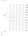
- FIG. 4 is a plan view of the first light of the side surface inspection device for a cylindrical battery according to one embodiment of the present invention.
- the first light 120 may include a plurality of first lighting units 120A to 120K disposed along the axial direction X of the cylindrical battery 200.
- eleven first lighting units 120A to 120K are formed, this is an example, and the number of first lighting units 120A to 120K is not particularly limited.
- Each of the plurality of first lighting units 120A to 120K may include a plurality of light emitters 121. However, each of the plurality of first lighting units 120A to 120K may include a singular light emitter 121.
- the light emitter 121 may be an LED. For the sake of convenience, only some of the plurality of light emitters 121 are denoted by reference numerals in the drawing.
- the camera 140 may capture at least a part of the first region A1 of the cylindrical battery 200, the image reflected on the first mirror 131, and the image reflected on the second mirror 132 multiple times.
- the first light 120 includes a plurality of first lighting units 120A to 120K
- the plurality of first lighting units 120A to 120K may emit light to the cylindrical battery 200 with different combinations in each of the multiple images capturing. Accordingly, by changing the emission angle of light, the visibility of defects of the cylindrical battery 200 can be improved.
- FIG. 5 is a plan view of the second light of the side surface inspection device for a cylindrical battery according to an embodiment of the present invention.
- the second light 160 may include a plurality of second lighting units 160A to 160E disposed along the direction of the cylindrical battery 200. Although five second lighting units 160A to 160E are shown in the drawing, this is an example, and the number of second lighting units 160A to 160E is not particularly limited.
- Each of the plurality of second lighting units 160A to 160E can include a plurality of light emitters 161. However, each of the plurality of second lighting units 160A to 160E can include a singular light emitter 161.
- the light emitter 161 may be an LED. For convenience of illustration, only some of the plurality of light emitters 161 are denoted by reference numerals in the drawings.
- the camera 140 can capture at least a part of the first region A1 of the cylindrical battery 200, the image reflected on the first mirror 131, and the image reflected on the second mirror 132 multiple times.
- the second light 160 includes a plurality of second lighting units 160A to 160E
- the plurality of second lighting units 160A to 160E can emit light to the cylindrical battery 200 with different combinations in each of the multiple images capturing. Accordingly, by changing the emission angle of light, the visibility of defects of the cylindrical battery 200 can be further improved.
- Table 1 shows exemplary combinations of the plurality of first lighting units 120A to 120K and the plurality of second lighting units 160A to 160E that emit light to the cylindrical battery 200 in each of the multiple images capturing.
- this is only an exemplary combination, and needless to say, the combination of the plurality of first lighting units 120A to 120K and the plurality of second lighting units 160A to 160E that emit light to the cylindrical battery 200 for each of the multiple image capturing is not limited to the combination shown in Table 1.
- the plurality of first lighting units 120A to 120K and the plurality of second lighting units 160A to 160E emit light to the cylindrical battery 200 by different combinations, the visibility of defects of the cylindrical battery 200 can be further improved.
- first and second are to distinguish components from each other and does not imply a priority between components or an absolute order.
- first component may be referred to as the second component in other parts of the specification.
Landscapes
- Chemical & Material Sciences (AREA)
- General Health & Medical Sciences (AREA)
- Life Sciences & Earth Sciences (AREA)
- Health & Medical Sciences (AREA)
- Analytical Chemistry (AREA)
- Biochemistry (AREA)
- Physics & Mathematics (AREA)
- General Physics & Mathematics (AREA)
- Immunology (AREA)
- Pathology (AREA)
- Chemical Kinetics & Catalysis (AREA)
- Electrochemistry (AREA)
- General Chemical & Material Sciences (AREA)
- Investigating Materials By The Use Of Optical Means Adapted For Particular Applications (AREA)
Applications Claiming Priority (2)
| Application Number | Priority Date | Filing Date | Title |
|---|---|---|---|
| KR1020210137099A KR102864164B1 (ko) | 2021-10-15 | 2021-10-15 | 원통형 전지 측면 검사 장치 |
| PCT/KR2022/012506 WO2023063561A1 (ko) | 2021-10-15 | 2022-08-22 | 원통형 전지 측면 검사 장치 |
Publications (3)
| Publication Number | Publication Date |
|---|---|
| EP4354123A1 true EP4354123A1 (de) | 2024-04-17 |
| EP4354123A4 EP4354123A4 (de) | 2024-10-30 |
| EP4354123B1 EP4354123B1 (de) | 2026-04-01 |
Family
ID=85987871
Family Applications (1)
| Application Number | Title | Priority Date | Filing Date |
|---|---|---|---|
| EP22881191.5A Active EP4354123B1 (de) | 2021-10-15 | 2022-08-22 | Vorrichtung zur prüfung der seitlichen oberfläche einer zylindrischen batterie |
Country Status (7)
| Country | Link |
|---|---|
| US (1) | US20240361252A1 (de) |
| EP (1) | EP4354123B1 (de) |
| JP (1) | JP7678214B2 (de) |
| KR (1) | KR102864164B1 (de) |
| CN (1) | CN117730250A (de) |
| CA (1) | CA3233838A1 (de) |
| WO (1) | WO2023063561A1 (de) |
Families Citing this family (2)
| Publication number | Priority date | Publication date | Assignee | Title |
|---|---|---|---|---|
| EP4672421A1 (de) * | 2023-12-27 | 2025-12-31 | LG Energy Solution, Ltd. | Zylindrische batteriezelleninspektionsvorrichtung und damit hergestellte zylindrische batteriezelle sowie batteriepack und fahrzeug mit zylindrischer batteriezelle |
| KR102810413B1 (ko) * | 2024-09-30 | 2025-05-22 | (주)인스케이프 | 원통형 물체 표면의 멀티 필드 레이어 검사 방법 |
Family Cites Families (14)
| Publication number | Priority date | Publication date | Assignee | Title |
|---|---|---|---|---|
| US5448365A (en) * | 1992-05-15 | 1995-09-05 | Philip Morris Incorporated | Systems for optical inspection |
| US5936725A (en) * | 1997-10-28 | 1999-08-10 | Materials Technologies Corp. | Apparatus and method for viewing and inspecting a circumferential surface area of a test object |
| IT1299859B1 (it) * | 1998-02-23 | 2000-04-04 | Gd Spa | Unita' elettro-ottica di rilevamento dell'intera superficie lateale di articoli di forma sostanzialmente cilindrica. |
| JP4619880B2 (ja) * | 2005-07-05 | 2011-01-26 | 株式会社日鉄エレックス | 円筒状物体の外観検査装置 |
| KR101030449B1 (ko) * | 2009-08-17 | 2011-04-25 | 홍익대학교 산학협력단 | 원통형 이차 전지 외관 검사 장치 |
| US8570504B2 (en) * | 2011-05-17 | 2013-10-29 | Gii Acquisition, Llc | Method and system for optically inspecting parts |
| KR101366188B1 (ko) * | 2012-02-03 | 2014-02-25 | 주식회사 서울금속 | 측면 및 표면 검사기능을 갖는 비전 검사 장치 |
| JP5946705B2 (ja) * | 2012-07-03 | 2016-07-06 | リコーエレメックス株式会社 | 検査装置および検査方法 |
| JP2016050864A (ja) * | 2014-09-01 | 2016-04-11 | 三菱電機株式会社 | 半田付外観検査装置 |
| JP6610367B2 (ja) * | 2016-03-22 | 2019-11-27 | 富士通株式会社 | 被検査対象物の検査装置及び検査方法 |
| KR102137539B1 (ko) * | 2018-07-12 | 2020-07-24 | (주) 인텍플러스 | 배터리 외관 검사장치 |
| DK201970154A1 (en) | 2019-03-06 | 2020-09-08 | Imbox Shoecare As | After treatment system |
| KR102274922B1 (ko) * | 2019-12-27 | 2021-07-08 | (주) 인텍플러스 | 슬릿빔을 이용한 배터리 외관 검사장치 |
| KR102890287B1 (ko) | 2020-02-13 | 2025-11-21 | 주식회사 엘지에너지솔루션 | 원통형 전지 및 원통형 전지 제조 방법 |
-
2021
- 2021-10-15 KR KR1020210137099A patent/KR102864164B1/ko active Active
-
2022
- 2022-08-22 EP EP22881191.5A patent/EP4354123B1/de active Active
- 2022-08-22 CN CN202280051028.0A patent/CN117730250A/zh active Pending
- 2022-08-22 WO PCT/KR2022/012506 patent/WO2023063561A1/ko not_active Ceased
- 2022-08-22 US US18/291,088 patent/US20240361252A1/en active Pending
- 2022-08-22 CA CA3233838A patent/CA3233838A1/en active Pending
- 2022-08-22 JP JP2024502170A patent/JP7678214B2/ja active Active
Also Published As
| Publication number | Publication date |
|---|---|
| EP4354123B1 (de) | 2026-04-01 |
| US20240361252A1 (en) | 2024-10-31 |
| KR102864164B1 (ko) | 2025-09-24 |
| JP2024524712A (ja) | 2024-07-05 |
| WO2023063561A1 (ko) | 2023-04-20 |
| EP4354123A4 (de) | 2024-10-30 |
| JP7678214B2 (ja) | 2025-05-15 |
| KR20230053841A (ko) | 2023-04-24 |
| CA3233838A1 (en) | 2023-04-20 |
| CN117730250A (zh) | 2024-03-19 |
Similar Documents
| Publication | Publication Date | Title |
|---|---|---|
| EP4354123A1 (de) | Vorrichtung zur prüfung der seitlichen oberfläche einer zylindrischen batterie | |
| US7924418B2 (en) | Inspection apparatus and method | |
| US6034766A (en) | Optical member inspection apparatus | |
| KR102713111B1 (ko) | 이차전지 결함 검사장치 및 방법 | |
| CN101071107A (zh) | 图像检查装置以及采用该图像检查装置的图像检查方法 | |
| CN105556292A (zh) | 用于轮胎内表面的肉眼检查的图像采集装置与相关方法 | |
| JP2010016048A (ja) | ウエハ用検査装置 | |
| JP7741292B2 (ja) | 円筒形電池の側面検査装置 | |
| KR102524888B1 (ko) | 연료전지 분리판 외관 검사 시스템 | |
| US11499921B2 (en) | Inspection method and inspection system for pillar-shaped honeycomb structure | |
| KR102917430B1 (ko) | 전극 표면 검사 장치 | |
| CN116359236A (zh) | 检测装置 | |
| JP2003156453A (ja) | 側面検査方法 | |
| CN206363036U (zh) | 液晶屏外观图像采集装置及通用检测设备 | |
| JP2011133288A (ja) | 筒状物品の画像検査用照明方法およびその照明装置 | |
| KR102773202B1 (ko) | 연료전지 분리판 외관 검사 시스템 | |
| KR20240091521A (ko) | 원통형 셀의 외관불량 검사장치 | |
| JP2001168010A (ja) | 基板の検査方法及び検査装置 | |
| JP2010261724A (ja) | タイヤ内面検査装置 | |
| JP4481094B2 (ja) | 金属リングの側縁検査装置 | |
| KR102903248B1 (ko) | 배터리 외관 검사 시스템 | |
| CN111361953A (zh) | 一种手机智能检测设备 | |
| JP2005083959A (ja) | 搬送基板不良検出装置及びこの搬送基板不良検出装置を備えたレーザトリミングマシン | |
| KR20260058115A (ko) | 배터리 검사 장치 및 배터리 검사 방법 | |
| JP2007292684A (ja) | 外観形状検査方法およびその装置 |
Legal Events
| Date | Code | Title | Description |
|---|---|---|---|
| STAA | Information on the status of an ep patent application or granted ep patent |
Free format text: STATUS: THE INTERNATIONAL PUBLICATION HAS BEEN MADE |
|
| PUAI | Public reference made under article 153(3) epc to a published international application that has entered the european phase |
Free format text: ORIGINAL CODE: 0009012 |
|
| STAA | Information on the status of an ep patent application or granted ep patent |
Free format text: STATUS: REQUEST FOR EXAMINATION WAS MADE |
|
| 17P | Request for examination filed |
Effective date: 20240109 |
|
| AK | Designated contracting states |
Kind code of ref document: A1 Designated state(s): AL AT BE BG CH CY CZ DE DK EE ES FI FR GB GR HR HU IE IS IT LI LT LU LV MC MK MT NL NO PL PT RO RS SE SI SK SM TR |
|
| A4 | Supplementary search report drawn up and despatched |
Effective date: 20241002 |
|
| RIC1 | Information provided on ipc code assigned before grant |
Ipc: H01M 50/107 20210101ALI20240926BHEP Ipc: G01N 21/88 20060101ALI20240926BHEP Ipc: G01N 21/952 20060101AFI20240926BHEP |
|
| DAV | Request for validation of the european patent (deleted) | ||
| DAX | Request for extension of the european patent (deleted) | ||
| STAA | Information on the status of an ep patent application or granted ep patent |
Free format text: STATUS: EXAMINATION IS IN PROGRESS |
|
| 17Q | First examination report despatched |
Effective date: 20250506 |
|
| GRAP | Despatch of communication of intention to grant a patent |
Free format text: ORIGINAL CODE: EPIDOSNIGR1 |
|
| STAA | Information on the status of an ep patent application or granted ep patent |
Free format text: STATUS: GRANT OF PATENT IS INTENDED |
|
| INTG | Intention to grant announced |
Effective date: 20251113 |
|
| GRAS | Grant fee paid |
Free format text: ORIGINAL CODE: EPIDOSNIGR3 |
|
| GRAA | (expected) grant |
Free format text: ORIGINAL CODE: 0009210 |
|
| STAA | Information on the status of an ep patent application or granted ep patent |
Free format text: STATUS: THE PATENT HAS BEEN GRANTED |
|
| AK | Designated contracting states |
Kind code of ref document: B1 Designated state(s): AL AT BE BG CH CY CZ DE DK EE ES FI FR GB GR HR HU IE IS IT LI LT LU LV MC MK MT NL NO PL PT RO RS SE SI SK SM TR |
|
| REG | Reference to a national code |
Ref country code: CH Ref legal event code: F10 Free format text: ST27 STATUS EVENT CODE: U-0-0-F10-F00 (AS PROVIDED BY THE NATIONAL OFFICE) Effective date: 20260401 Ref country code: GB Ref legal event code: FG4D |
|
| REG | Reference to a national code |
Ref country code: IE Ref legal event code: FG4D |
|
| REG | Reference to a national code |
Ref country code: DE Ref legal event code: R096 Ref document number: 602022033727 Country of ref document: DE |