EP4354128A2 - Dispositif et procédé de calcul d'une trajectoire d'enregistrement - Google Patents
Dispositif et procédé de calcul d'une trajectoire d'enregistrement Download PDFInfo
- Publication number
- EP4354128A2 EP4354128A2 EP24161020.3A EP24161020A EP4354128A2 EP 4354128 A2 EP4354128 A2 EP 4354128A2 EP 24161020 A EP24161020 A EP 24161020A EP 4354128 A2 EP4354128 A2 EP 4354128A2
- Authority
- EP
- European Patent Office
- Prior art keywords
- recording
- trajectory
- calculation unit
- recorded
- measurement
- Prior art date
- Legal status (The legal status is an assumption and is not a legal conclusion. Google has not performed a legal analysis and makes no representation as to the accuracy of the status listed.)
- Granted
Links
Images

Classifications
-
- G—PHYSICS
- G01—MEASURING; TESTING
- G01N—INVESTIGATING OR ANALYSING MATERIALS BY DETERMINING THEIR CHEMICAL OR PHYSICAL PROPERTIES
- G01N23/00—Investigating or analysing materials by the use of wave or particle radiation, e.g. X-rays or neutrons, not covered by groups G01N3/00 – G01N17/00, G01N21/00 or G01N22/00
- G01N23/02—Investigating or analysing materials by the use of wave or particle radiation, e.g. X-rays or neutrons, not covered by groups G01N3/00 – G01N17/00, G01N21/00 or G01N22/00 by transmitting the radiation through the material
- G01N23/04—Investigating or analysing materials by the use of wave or particle radiation, e.g. X-rays or neutrons, not covered by groups G01N3/00 – G01N17/00, G01N21/00 or G01N22/00 by transmitting the radiation through the material and forming images of the material
- G01N23/046—Investigating or analysing materials by the use of wave or particle radiation, e.g. X-rays or neutrons, not covered by groups G01N3/00 – G01N17/00, G01N21/00 or G01N22/00 by transmitting the radiation through the material and forming images of the material using tomography, e.g. computed tomography [CT]
-
- G—PHYSICS
- G01—MEASURING; TESTING
- G01N—INVESTIGATING OR ANALYSING MATERIALS BY DETERMINING THEIR CHEMICAL OR PHYSICAL PROPERTIES
- G01N23/00—Investigating or analysing materials by the use of wave or particle radiation, e.g. X-rays or neutrons, not covered by groups G01N3/00 – G01N17/00, G01N21/00 or G01N22/00
- G01N23/02—Investigating or analysing materials by the use of wave or particle radiation, e.g. X-rays or neutrons, not covered by groups G01N3/00 – G01N17/00, G01N21/00 or G01N22/00 by transmitting the radiation through the material
- G01N23/06—Investigating or analysing materials by the use of wave or particle radiation, e.g. X-rays or neutrons, not covered by groups G01N3/00 – G01N17/00, G01N21/00 or G01N22/00 by transmitting the radiation through the material and measuring the absorption
- G01N23/18—Investigating the presence of flaws defects or foreign matter
-
- G—PHYSICS
- G01—MEASURING; TESTING
- G01N—INVESTIGATING OR ANALYSING MATERIALS BY DETERMINING THEIR CHEMICAL OR PHYSICAL PROPERTIES
- G01N2223/00—Investigating materials by wave or particle radiation
- G01N2223/10—Different kinds of radiation or particles
- G01N2223/101—Different kinds of radiation or particles electromagnetic radiation
- G01N2223/1016—X-ray
-
- G—PHYSICS
- G01—MEASURING; TESTING
- G01N—INVESTIGATING OR ANALYSING MATERIALS BY DETERMINING THEIR CHEMICAL OR PHYSICAL PROPERTIES
- G01N2223/00—Investigating materials by wave or particle radiation
- G01N2223/30—Accessories, mechanical or electrical features
- G01N2223/306—Accessories, mechanical or electrical features computer control
-
- G—PHYSICS
- G01—MEASURING; TESTING
- G01N—INVESTIGATING OR ANALYSING MATERIALS BY DETERMINING THEIR CHEMICAL OR PHYSICAL PROPERTIES
- G01N2223/00—Investigating materials by wave or particle radiation
- G01N2223/30—Accessories, mechanical or electrical features
- G01N2223/33—Accessories, mechanical or electrical features scanning, i.e. relative motion for measurement of successive object-parts
-
- G—PHYSICS
- G01—MEASURING; TESTING
- G01N—INVESTIGATING OR ANALYSING MATERIALS BY DETERMINING THEIR CHEMICAL OR PHYSICAL PROPERTIES
- G01N2223/00—Investigating materials by wave or particle radiation
- G01N2223/40—Imaging
- G01N2223/405—Imaging mapping of a material property
-
- G—PHYSICS
- G01—MEASURING; TESTING
- G01N—INVESTIGATING OR ANALYSING MATERIALS BY DETERMINING THEIR CHEMICAL OR PHYSICAL PROPERTIES
- G01N2223/00—Investigating materials by wave or particle radiation
- G01N2223/40—Imaging
- G01N2223/41—Imaging imaging specifically internal structure
-
- G—PHYSICS
- G01—MEASURING; TESTING
- G01N—INVESTIGATING OR ANALYSING MATERIALS BY DETERMINING THEIR CHEMICAL OR PHYSICAL PROPERTIES
- G01N2223/00—Investigating materials by wave or particle radiation
- G01N2223/40—Imaging
- G01N2223/419—Imaging computed tomograph
-
- G—PHYSICS
- G01—MEASURING; TESTING
- G01N—INVESTIGATING OR ANALYSING MATERIALS BY DETERMINING THEIR CHEMICAL OR PHYSICAL PROPERTIES
- G01N2223/00—Investigating materials by wave or particle radiation
- G01N2223/40—Imaging
- G01N2223/427—Imaging stepped imaging (selected area of sample is changed)
-
- G—PHYSICS
- G01—MEASURING; TESTING
- G01N—INVESTIGATING OR ANALYSING MATERIALS BY DETERMINING THEIR CHEMICAL OR PHYSICAL PROPERTIES
- G01N2223/00—Investigating materials by wave or particle radiation
- G01N2223/60—Specific applications or type of materials
- G01N2223/606—Specific applications or type of materials texture
-
- G—PHYSICS
- G01—MEASURING; TESTING
- G01N—INVESTIGATING OR ANALYSING MATERIALS BY DETERMINING THEIR CHEMICAL OR PHYSICAL PROPERTIES
- G01N2223/00—Investigating materials by wave or particle radiation
- G01N2223/60—Specific applications or type of materials
- G01N2223/648—Specific applications or type of materials voids
-
- G—PHYSICS
- G01—MEASURING; TESTING
- G01N—INVESTIGATING OR ANALYSING MATERIALS BY DETERMINING THEIR CHEMICAL OR PHYSICAL PROPERTIES
- G01N2223/00—Investigating materials by wave or particle radiation
- G01N2223/60—Specific applications or type of materials
- G01N2223/66—Specific applications or type of materials multiple steps inspection, e.g. coarse/fine
-
- G—PHYSICS
- G01—MEASURING; TESTING
- G01N—INVESTIGATING OR ANALYSING MATERIALS BY DETERMINING THEIR CHEMICAL OR PHYSICAL PROPERTIES
- G01N23/00—Investigating or analysing materials by the use of wave or particle radiation, e.g. X-rays or neutrons, not covered by groups G01N3/00 – G01N17/00, G01N21/00 or G01N22/00
- G01N23/02—Investigating or analysing materials by the use of wave or particle radiation, e.g. X-rays or neutrons, not covered by groups G01N3/00 – G01N17/00, G01N21/00 or G01N22/00 by transmitting the radiation through the material
- G01N23/06—Investigating or analysing materials by the use of wave or particle radiation, e.g. X-rays or neutrons, not covered by groups G01N3/00 – G01N17/00, G01N21/00 or G01N22/00 by transmitting the radiation through the material and measuring the absorption
- G01N23/083—Investigating or analysing materials by the use of wave or particle radiation, e.g. X-rays or neutrons, not covered by groups G01N3/00 – G01N17/00, G01N21/00 or G01N22/00 by transmitting the radiation through the material and measuring the absorption the radiation being X-rays
Definitions
- Embodiments of the present invention relate to a device and a corresponding method for calculating an acquisition trajectory of a CT system.
- a further embodiment relates to a corresponding computer program.
- X-ray computer tomography requires a data set of radiographic images that is as complete as possible. Such a data set is as complete as possible when the image data processing that follows the recording of individual X-ray radiographic images, e.g. reconstruction, can answer a question from a test task with sufficient accuracy.
- a specific sequence of source, object and detector positions and orientations is called a trajectory.
- Classical CT systems address this task by manipulating the object or source and detector with the aim of generating a trajectory that scans as large a part of a circle as possible and as finely as possible.
- the object of the present invention is to create a concept that optimizes the recording trajectory of a CT system in such a way that the number of recordings is reduced and yet the data set determined by means of the recordings is sufficient to fulfill the inspection task.
- Embodiments of the present invention provide a calculation unit for calculating a recording trajectory of a CT system.
- the calculation unit comprises a receiving interface, an optimizer and a control unit.
- the receiving interface is used to receive measurement data, such as intermediate images or already calculated object data, or simulation data relating to the object to be recorded, i.e. for example from an X-ray simulation (which is based on CAD data of the object to be recorded, for example).
- the optimizer is designed to determine the recording trajectory to be followed based on the known degrees of freedom of the CT system (rotational CT system or helical CT system or CT system with a large number of degrees of freedom), based on the measurement and/or simulation data explained above and based on a test task.
- the test task comes from a group comprising a plurality of test tasks, such as creating a volume model, creating a surface model or detecting defects.
- data is now output that is used to control a manipulation unit (e.g. with one or more actuators/robots) of the computer tomography system.
- This can either be control data or general data that describes the position and is then approached by the control system.
- the invention is therefore based on the knowledge that in X-ray imaging systems or CT systems that are able to capture 2D, 3D or 4D (3D + time) information of an object, the trajectory or generally the positions to be traveled can be optimized with knowledge of the specific inspection task and with knowledge of the inspection object in such a way that the number of individual images and thus also the positions to be traveled to is reduced.
- Every task such as the detection of surface geometry compared to the detection of a volume model, predetermines the boundary conditions for the trajectory but also for the recording parameters, such as X-ray voltage or exposure time.
- the object itself has or can have a further influence.
- the simpler the object and the simpler the inspection task surface determination
- the angles approached in space should be sufficiently distributed along the movement path (trajectory). If the inspection task (e.g. detection of cavities) and the geometry of the inspection object are very complex, the number of angles approached in space should generally be increased so that a sufficiently high resolution can be achieved in the volume model.
- the optimizer defines the trajectory (i.e. the sequence of position and orientation of the manipulators) so that - under certain circumstances - an image with optimal quality or sufficient quality for a task is created with as few individual images as possible.
- This has the advantage that optimal image quality can be achieved with a minimum number of X-ray projections and thus with a very short measurement time. This speeds up each measurement sufficiently for the respective test task.
- interim data generated during the measurement that is sufficiently good to identify the boundary conditions of the object (e.g. undercuts or strongly varying surfaces, such as in the case of a heat sink) or a geometry or volume model that is derived from the CAD data, for example, serve as measurement and/or simulation data.
- the intermediate images or the interim data output by the image processing e.g. voxel model that has not yet been fully reconstructed or for which the database is not yet final, or intermediate images, i.e. 2D data
- the partially constructed data set can serve as input variables before calculating the trajectory.
- the calculation unit has a user interface via which the respective test task can be defined.
- a first test task relates to the averaging of a geometric structure and/or a geometric surface structure.
- the recording trajectory or the Settings of the CT system are selected so that high-frequency features of the object to be recorded can be easily scanned and in particular large gradients, such as those resulting from edges, can be detected when recording the object to be recorded.
- a second test task according to a further embodiment relates to the detection of attenuation coefficients across the volume of the object to be recorded.
- the requirements for the recording and thus also for the recording trajectory are higher.
- the attenuation coefficient can be seen as a material property which, in combination with additional knowledge (e.g. material density), allows conclusions to be drawn about the material. In this respect, longer recording or exposure times and also a higher number of angles in space are usually required.
- a further test task according to an embodiment relates to the determination of deviations, such as errors or voids, in the volume of the object to be recorded.
- deviations such as errors or voids
- the recording trajectory can then be selected in such a way that individual areas that indicate a local density variation are zoomed in. According to embodiments, it would also be conceivable that a gradual improvement is sought in such areas. It would also be possible to traverse a Fibonacci grid on a spherical surface. It would also be possible to traverse a trajectory with variable magnification.
- the recording trajectory could also be selected in such a way that collisions, such as with the object or with the test environment, are avoided. This is possible because, once the object is known, the free space is sufficiently well known based on the previously determined measurement or simulation data.
- the optimizer can also be designed to specify the recording parameters for each position on the recording trajectory or, to be more precise, to vary them. If, for example, the object has a different, e.g. thinner, length in one spatial direction than in the other spatial direction, a short exposure time can be selected or be sufficient, while for the longer length the exposure time for this angle in space must be increased accordingly.
- the recording parameters are adjusted not only for the exposure time, but also for the X-ray voltage, the X-ray current or an X-ray filter.
- the correction data can also vary for each angle in space and can therefore advantageously be stored in addition to the respective positions on the recording trajectory.
- the correction data are essentially the so-called bright images, on the basis of which calibration takes place. If such a bright image is not available for every position on the recording trajectory, it can be determined or simulated based on the neighboring positions.
- Another embodiment relates to a CT system with an optimizer as characterized above.
- a further embodiment provides a corresponding method with the steps of receiving measurement and simulation data, determining the recording trajectory and outputting the data for controlling the manipulation unit.
- a computer program can be used to carry out the method.
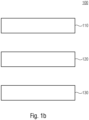
- Fig.1 shows a calculation unit 10 for calculating an acquisition trajectory of a CT system.
- the calculation unit comprises the peripheral interface 12, the optimizer 20 and a control unit 14. Furthermore, the calculation unit in this embodiment has an interface 16 for receiving a current acquisition situation (eg position/orientation of the object).
- Measurement and/or simulation data relating to the object to be recorded are obtained via the interface 12.
- these are the simulation data from an X-ray simulation of the object 30 to be recorded, whereby the X-ray simulation can be based, for example, on CAD data relating to the object 30 to be recorded.
- this receiving of the measurement and/or simulation data corresponds to step 110.
- This data is then analyzed by the optimizer and processed in combination with the corresponding case (see reference symbols F1 to F3), which is obtained via the user interface 16, such that the recording trajectory 32 is determined.
- This step corresponds to step 120 in the method 100.
- the number and positions on the recording trajectory 32 can be reduced in such a way that, for example, only four or slightly more recordings need to be taken along the side surfaces of the square cube 30 in order to then determine good gradient images that indicate the edges.
- the recording trajectory 32' could also be determined in such a way that a large number of positions along the recording trajectory 32' are recorded in order to be able to determine a sufficiently detailed voxel model for the cube-shaped object 30 in which irregularities in the density distribution can be recognized.
- the alternative or additive test task F2 "Determining a volume data set" (with the aim of material recognition) specified according to a further embodiment would, based on the cube-shaped test body 30, not require such a detailed database as, for example, in the test task F3, but would nevertheless require a higher level of detail than in the test task F1.
- Image is understood here to mean a quantity (or part thereof) of spatially resolved information that exists about the test object (CT volume, defect list, edge image, surface mesh, ).
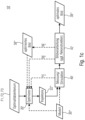
- FIG. 1c A further embodiment of a device 10' with an optimizer 20' is explained.
- a measurement and simulation unit 40' and an image processing unit 42' are provided, which are usually part of the CT system.
- the measurement and simulation unit 40' receives the recording trajectory 32* and controls the CT system on the basis of this.
- the block 42 downstream of the measurement and simulation receives the corresponding intermediate images 37* from the measurement and simulation for reconstruction. From this, either a raw data set (voxel model, see reference number 37*) or an optimized image 38* can be output.
- the optimized image can be understood not only as the surface geometry, the volume model, but also as a list of positions of defects or other information.
- the optimized image 38* is output in particular to the output interface of the CT system, but can also be output to the optimizer 20', which calculates its trajectory 32* on this basis.
- test task F1 includes the trajectory 32*1
- test task F2 includes the trajectory 32*2
- test task F3 includes the trajectory 32*3.
- the optimizer 20' may, under certain circumstances, refer to a given or during the measurement generated, optimal or non-optimal model 30' (prior knowledge, CAD, surface model) of the test object and/or the structure and manipulators of the test system in order to optimize the recording trajectory 32* with regard to information such as object geometry, accessibility, material and structure.
- Trajectory 32*1 - 32*3 refers to the sequence of positions and orientations of one or more X-ray tubes, one or more X-ray detectors and one or more objects via a common or several independent positioning systems
- the trajectory can contain the parameters of the X-ray source and the detector (voltage, filtering, current, exposure time).
- the optimizer 20' optimizes and defines the trajectory 32*1 - 32*3 with regard to the optimality criterion 1), 2) or 3), if necessary iteratively.
- the optimizer uses one or more pieces of information, namely the optimal or non-optimal model 30', the result or intermediate result of the iterative optimization ("optimized image 38*"), the result or intermediate result of a single X-ray image (see 37*) and the result or intermediate result of image processing (see 39*).
- the result or intermediate result of an X-ray image can also be created by an X-ray simulation instead of by measurement.
- the relationships are shown in Fig. 1c clarified.
- test tasks F1 to F3 Although the above example only ever addressed test tasks F1 to F3, it should be noted at this point that there may also be further test tasks or variations of test tasks F1 to F3.
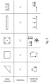
- the table from Fig.2 shows a total of four columns with four test objects and four associated test tasks.
- a triangular test object is to be recognized in accordance with test task F1 "Surface structure detection”.
- a rectangular object is to be examined once with test task F1 "Surface structure detection” (column 2) and once with test task F3 "Detection of defects” (column 3).
- a flat element such as a pane, is to be examined based on test task F2 "Detection of a volume model”.
- a body with undercuts e.g. a heat sink, is shown, the surface of which is to be scanned (F1).
- the trajectory is selected in such a way that angles in space offset by about 90° or 92° (general angles in the range between 85° and 100°, preferably greater than 90°) are approached on the trajectory in order to enable surface detection.
- angles in space offset by about 90° or 92° generally angles in the range between 85° and 100°, preferably greater than 90°
- the other two angles in space shown in dashed lines can also be approached in order to enable verification here.
- the intermediate images are taken into account when determining the trajectory.
- the first radiation is obliquely transmitted (see dotted line), so that variations (starting from this first radiation angle, e.g. by 90° each time) would result in an incorrect measurement.
- variations starting from this first radiation angle, e.g. by 90° each time
- no sharp gradient can be seen in this oblique radiation, so that a corresponding angle in space is then sought for the second angle in space that offers a sufficiently high gradient, so that the two or four optimal angles in space are then reached.
- the example in the third column is the same object as in the second column, but for a different test task.
- a large number of parallel images and a further large number of parallel images offset by 90° are taken, or the cube is irradiated at a large number of different angles in space around the 360° axis.
- the example in column 4 is a surface where the density is to be determined over the entire object volume.
- the radiation path parallel to the surface makes it clear that a very large volume has to be irradiated, which requires considerably long exposure times in order to achieve sufficient accuracy.
- transverse radiation through the thin plane
- it is not necessary to work with such long exposure times so that the exposure time can be reduced accordingly.
- the beam path between the radiation source and the X-ray detector may not allow the entire surface to be irradiated. This is indicated by the additional dotted line.
- Arrow in the line "possible angles in space".
- the orientation of the object in space also plays a decisive role, since, for example, the heat sink can be scanned easily from the side (ie transversely to the cooling fins), but difficultly from above or below.
- unusual trajectories can also be approached, e.g. when zooming in in the example from column 3.
- the claimed classes of X-ray recording trajectories include, for example, successively improving recording trajectories (for example Fibonacci grids on the surface of a sphere), scanning with constant magnification with trajectories on spherical surfaces, trajectories in which the X-ray source, detector and object are not on a straight line or the X-ray source is not on the normal of the X-ray detector in the center of its image and in particular trajectories for scanning the object with variable magnification, i.e. with variable distances from the X-ray source and detector to the object.
- variable magnification i.e. with variable distances from the X-ray source and detector to the object.
- the trajectories can be optimized with regard to different boundary conditions of the actually implemented recording or manipulation system. This can include, for example: Avoiding collisions with the object, with the manipulation system itself, with the room or with people in the workspace, taking into account accessible, inaccessible or partially accessible positions in the workspace of the manipulation system, different precision achievable by the manipulation system at different points in the workspace, at different travel speeds, different directions of movement or different changes in the direction of movement or speed. This means in particular that trajectories are created which minimize the total time required for a measurement.
- the parameter exposure time, current, voltage and filtering can also be optimized in parallel to the trajectories as part of a trajectory optimization. This optimally determines the tuple of these parameters for the entire measurement or for each X-ray image individually.
- Bright images are the detector images required to correct inhomogeneous detector properties and illumination without any object in the beam path. If the relative position and orientation of the X-ray source to the detector or the X-ray parameters such as exposure time, current, voltage, filtering are not constant over a measurement, these correction images are also not constant and can only be determined by measurement with corresponding effort.
- the variable part of these bright images is either calculated from the previously recorded radiation field of the X-ray tube or estimated using X-ray simulation of the recording geometry and parameters.
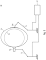
- Fig.3 a computed tomography system 80 based on robots 72 and 74 is explained.
- Fig. 3a shows a possible computer tomography system 80 in which the X-ray source 70s is arranged on a first robot 72, while the radiation detector 70d is provided on a second robot 74.
- the X-ray source 70s and the radiation detector 70d can be varied as desired in space.
- the two elements 70s and 70d can be moved on the trajectory 76, here a circular path, so that the corresponding Angles in space.
- the radius of the circular path can be reduced, as shown here using the dashed line 76', for example to achieve a higher spatial resolution.
- the different positions do not have to lie on one and the same circular path, ie not in a common plane, but can be distributed anywhere in space around the object (which is advantageously made possible by the CT system 80 with its two robots 72 and 74).
- this means that the trajectories are defined by any positions that can be approached by the robots 72 and 74.
- the computed tomography system 80 is provided with the calculation unit 10", the robots 72 and 74 and the modules of the X-ray unit 70s and 70d.
- the object to be examined can be held by another robot, whose freedom of movement can be used to realize a trajectory.
- the CT system comprises more than 2 robots.
- Further embodiments enable automatic path planning for complex recording systems, so that in addition to optimal image quality, limitations of the recording system such as accessibility, precision or speed are also taken into account.
- the method according to the above embodiments is particularly relevant for the computer tomography of large and/or complexly shaped components, for example from automotive engineering, aerospace, with new recording systems with a high number of degrees of freedom in a large workspace, such as robot-based computer tomography.
- the method can help accelerate rapid production-integrated inline computed tomography and thus increase the rate and efficiency of testing.
- the procedure can also generally contribute to an improvement in image quality in computed tomography and thus lead to more reliable representation of finer structures.
- the procedure can be transferred to medical applications in order to contribute to improved image quality and reduced dose exposure for the patient.
- a calculation unit 10, 10', 10" for calculating a recording trajectory of a CT system has the following features: a receiving interface 12 for receiving measurement and/or simulation data relating to the object to be recorded; an optimizer 20, 20', which is designed to determine the recording trajectory based on known degrees of freedom of the CT system, based on the measurement and/or simulation data and based on a test task from a group comprising a plurality of test tasks; and a control unit 14, which is designed to output data corresponding to the calculated recording trajectory for controlling a manipulation unit of the CT system.
- the measurement and/or simulation data comprise an optimal model generated during a measurement or a non-optimal model generated during a measurement, comprising a geometry model and/or volume model.
- the measurement and/or simulation data are taken when the object to be recorded is recorded with the CT system.
- the measurement and/or simulation data comprise intermediate images and/or interim data n output by the image processing 42'.
- the measurement and/or simulation data comprise a data object calculated by the image processing 42' according to the test task.
- the calculation unit has a user interface 16 via which the test task is selected.
- the group comprising a plurality of testing tasks includes the testing task of determining a geometric structure and/or geometric surface structure.
- the positions on the recording trajectory are selected such that high-frequency features of the object to be recorded and/or gradients can be detected when recording the object to be recorded.
- the group of inspection tasks comprises the detection of properties of the materials over the volume of the object to be recorded.
- the positions of the recording trajectories are selected such that attenuation coefficients and/or the density of the materials in the volume of the object to be recorded can be detected in the recordings.
- the group of inspection tasks comprises determining deviations in the volume of the object to be recorded.
- the positions on the recording trajectory are selected such that local variations in attenuation coefficients are detectable in the recordings.
- each further position on the recording trajectory is selected such that a successive improvement of the image to be recorded is achieved; and/or the positions on the recording trajectory are selected with variable magnification and/or with decreasing distance between the object to be recorded and image capture means.
- the optimizer 20, 20' is designed to select the positions on the recording trajectory such that a collision between the recording means and the object to be recorded is prevented.
- the positions of the recording trajectory are selected such that a collision between the recording means and the environment of the object to be recorded is prevented.
- the optimizer 20, 20' is designed to predetermine the recording parameters for each position on the recording trajectory, and wherein the recording parameters vary between two positions on the recording trajectory; and/or wherein the recording parameters include exposure time, X-ray voltage, X-ray current and/or filtering.
- the optimizer 20, 20' determines correction data for each position on the recording trajectory from a set of stored correction data or calculates the same corrected correction data based on the stored correction data for neighboring positions; and/or wherein the optimizer 20, 20' determines correction data from a memory for the selected recording parameters or calculates corrected correction data based on the stored correction data for similar parameters.
- An eighteenth aspect relates to a calculation unit 10, 10', 10" for calculating a recording trajectory of a CT system, having the following features: a receiving interface 12 for receiving measurement and/or simulation data relating to the object to be recorded; an optimizer 20, 20', which is designed to determine the recording trajectory based on known degrees of freedom of the CT system, based on the measurement and/or simulation data and based on a test task from a group comprising a plurality of test tasks; and a control unit 14, which is designed to output data corresponding to the calculated recording trajectory for controlling a manipulation unit of the CT system; wherein the group comprising a plurality of test tasks includes the test task of determining a geometric structure and/or geometric surface structure; wherein the group of test tasks includes the detection of properties of the materials over the volume of the object to be recorded; wherein the group of test tasks includes the determination of deviations in the volume of the object to be recorded; wherein the optimizer 20, 20' is designed to specify the recording parameters for each position on the recording trajectory and wherein the recording
- a nineteenth aspect relates to a computed tomography system 80 with a calculation unit 10, 10', 10" according to one of the previous aspects.
- a method 100 for calculating a recording trajectory of a computed tomography system comprises the following steps: receiving 110 measurement and/or simulation data relating to the object to be recorded; determining 120 the recording trajectory based on known degrees of freedom of the CT system, based on the measurement and/or simulation data and based on a test task from a group comprising a plurality of test tasks, and outputting 130 data corresponding to the calculated recording trajectory for controlling a manipulation unit of the computed tomography system.
- a twenty-first aspect relates to a computer program for carrying out the method according to aspect 20 when the program runs on a computer.
- aspects have been described in connection with a device, it is to be understood that these aspects also represent a description of the corresponding method, so that a block or component of a device can also be understood as a corresponding method step or as a feature of a method step. Analogously, aspects described in connection with or as a method step also represent a description of a corresponding block or detail or feature of a corresponding device.
- Some or all of the method steps can be carried out by a hardware device (or using a hardware device), such as a microprocessor, a programmable computer or an electronic circuit. In some According to embodiments, some or more of the most important method steps can be carried out by such an apparatus.
- embodiments of the invention may be implemented in hardware or in software.
- the implementation may be performed using a digital storage medium, for example a floppy disk, a DVD, a Blu-ray Disc, a CD, a ROM, a PROM, an EPROM, an EEPROM or a FLASH memory, a hard disk or other magnetic or optical storage on which electronically readable control signals are stored that can or do interact with a programmable computer system in such a way that the respective method is carried out. Therefore, the digital storage medium may be computer readable.
- Some embodiments according to the invention thus comprise a data carrier having electronically readable control signals capable of interacting with a programmable computer system such that one of the methods described herein is carried out.
- embodiments of the present invention may be implemented as a computer program product having a program code, wherein the program code is operable to perform one of the methods when the computer program product is run on a computer.
- the program code can, for example, also be stored on a machine-readable medium.
- inventions include the computer program for performing one of the methods described herein, wherein the computer program is stored on a machine-readable medium.
- an embodiment of the method according to the invention is thus a computer program which has a program code for carrying out one of the methods described herein when the computer program runs on a computer.
- a further embodiment of the methods according to the invention is thus a data carrier (or a digital storage medium or a computer-readable medium) on which the computer program for carrying out one of the methods described herein is recorded.
- a further embodiment of the method according to the invention is thus a data stream or a sequence of signals which represents the computer program for carrying out one of the methods described herein.
- the data stream or the sequence of signals can be configured, for example, to be transferred via a data communication connection, for example via the Internet.
- a further embodiment comprises a processing device, for example a computer or a programmable logic device, which is configured or adapted to carry out one of the methods described herein.
- a processing device for example a computer or a programmable logic device, which is configured or adapted to carry out one of the methods described herein.
- a further embodiment comprises a computer on which the computer program for carrying out one of the methods described herein is installed.
- a further embodiment according to the invention comprises a device or a system which is designed to transmit a computer program for carrying out at least one of the methods described herein to a recipient.
- the transmission can be carried out electronically or optically, for example.
- the recipient can be, for example, a computer, a mobile device, a storage device or a similar device.
- the device or system can, for example, comprise a file server for transmitting the computer program to the recipient.
- a programmable logic device e.g., a field programmable gate array, an FPGA
- a field programmable gate array may interact with a microprocessor to perform any of the methods described herein.
- the methods are performed by any hardware device. This may be general-purpose hardware such as a computer processor (CPU) or hardware specific to the method such as an ASIC.
Landscapes
- Health & Medical Sciences (AREA)
- Immunology (AREA)
- Pathology (AREA)
- Chemical & Material Sciences (AREA)
- Analytical Chemistry (AREA)
- Biochemistry (AREA)
- General Health & Medical Sciences (AREA)
- General Physics & Mathematics (AREA)
- Physics & Mathematics (AREA)
- Life Sciences & Earth Sciences (AREA)
- Engineering & Computer Science (AREA)
- Nuclear Medicine, Radiotherapy & Molecular Imaging (AREA)
- Pulmonology (AREA)
- Radiology & Medical Imaging (AREA)
- Theoretical Computer Science (AREA)
- Analysing Materials By The Use Of Radiation (AREA)
- Apparatus For Radiation Diagnosis (AREA)
- Magnetic Resonance Imaging Apparatus (AREA)
Applications Claiming Priority (3)
| Application Number | Priority Date | Filing Date | Title |
|---|---|---|---|
| DE102016213403.5A DE102016213403A1 (de) | 2016-07-21 | 2016-07-21 | Vorrichtung und Verfahren zur Berechnung einer Aufnahmetrajektorie |
| EP17755067.0A EP3488232B1 (fr) | 2016-07-21 | 2017-07-18 | Dispositif et procédé pour calculer une trajectoire d'enregistrement pour la tomodensitométrie |
| PCT/EP2017/068098 WO2018015373A1 (fr) | 2016-07-21 | 2017-07-18 | Dispositif et procédé pour calculer une trajectoire d'enregistrement pour la tomodensitométrie |
Related Parent Applications (1)
| Application Number | Title | Priority Date | Filing Date |
|---|---|---|---|
| EP17755067.0A Division EP3488232B1 (fr) | 2016-07-21 | 2017-07-18 | Dispositif et procédé pour calculer une trajectoire d'enregistrement pour la tomodensitométrie |
Publications (3)
| Publication Number | Publication Date |
|---|---|
| EP4354128A2 true EP4354128A2 (fr) | 2024-04-17 |
| EP4354128A3 EP4354128A3 (fr) | 2024-07-17 |
| EP4354128B1 EP4354128B1 (fr) | 2026-08-12 |
Family
ID=59683496
Family Applications (3)
| Application Number | Title | Priority Date | Filing Date |
|---|---|---|---|
| EP24161019.5A Pending EP4354127A3 (fr) | 2016-07-21 | 2017-07-18 | Dispositif et procédé de calcul d'une trajectoire d'enregistrement |
| EP24161020.3A Active EP4354128B1 (fr) | 2016-07-21 | 2017-07-18 | Dispositif et procédé de calcul d'une trajectoire d'enregistrement |
| EP17755067.0A Active EP3488232B1 (fr) | 2016-07-21 | 2017-07-18 | Dispositif et procédé pour calculer une trajectoire d'enregistrement pour la tomodensitométrie |
Family Applications Before (1)
| Application Number | Title | Priority Date | Filing Date |
|---|---|---|---|
| EP24161019.5A Pending EP4354127A3 (fr) | 2016-07-21 | 2017-07-18 | Dispositif et procédé de calcul d'une trajectoire d'enregistrement |
Family Applications After (1)
| Application Number | Title | Priority Date | Filing Date |
|---|---|---|---|
| EP17755067.0A Active EP3488232B1 (fr) | 2016-07-21 | 2017-07-18 | Dispositif et procédé pour calculer une trajectoire d'enregistrement pour la tomodensitométrie |
Country Status (4)
| Country | Link |
|---|---|
| US (1) | US11016041B2 (fr) |
| EP (3) | EP4354127A3 (fr) |
| DE (1) | DE102016213403A1 (fr) |
| WO (1) | WO2018015373A1 (fr) |
Families Citing this family (6)
| Publication number | Priority date | Publication date | Assignee | Title |
|---|---|---|---|---|
| DE102019213983A1 (de) | 2019-09-13 | 2021-03-18 | Fraunhofer-Gesellschaft zur Förderung der angewandten Forschung e.V. | Vorrichtung und verfahren zum bestimmen eines aufnahmeparameters und/oder zum bereitstellen einer wartungsempfehlung für eine computertomographieanlage |
| DE202019105077U1 (de) | 2019-09-13 | 2019-11-18 | Fraunhofer-Gesellschaft zur Förderung der angewandten Forschung e.V. | Vorrichtung zum Bestimmen eines Aufnahmeparameters und/oder zum Bereitstellen einer Wartungsempfehlung für eine Computertomographieanlage |
| CN110702706B (zh) * | 2019-09-20 | 2022-05-20 | 天津大学 | 一种能谱ct系统输出数据的模拟方法 |
| US12092591B2 (en) | 2021-06-30 | 2024-09-17 | Illinois Tool Works Inc. | Scan procedure generation systems and methods to generate scan procedures |
| DE102024132169B3 (de) * | 2024-11-05 | 2025-12-24 | Dr. Ing. H.C. F. Porsche Aktiengesellschaft | Verfahren zur Ermittlung von optimierten Projektionsansichten für eine scharfe Objektkantenabbildung für ein mittels Roboter-Computertomographie zu überprüfendes Objekt |
| CN121040947B (zh) * | 2024-12-26 | 2026-06-30 | 北京歌锐科技有限公司 | 一种数据显示方法、装置、介质及设备 |
Family Cites Families (12)
| Publication number | Priority date | Publication date | Assignee | Title |
|---|---|---|---|---|
| US5073910A (en) * | 1990-08-27 | 1991-12-17 | General Electric Company | Square wave cone beam scanning trajectory for data completeness in three-dimensional computerized tomography |
| DE4335301C1 (de) * | 1993-10-15 | 1994-12-08 | Siemens Ag | Medizinische Anlage |
| WO2004080309A2 (fr) * | 2003-03-10 | 2004-09-23 | Philips Intellectual Property & Standards Gmbh | Dispositif et procede d'adaptation des parametres d'enregistrement d'un radiogramme |
| WO2006042211A2 (fr) * | 2004-10-07 | 2006-04-20 | University Of Florida Research Foundation, Inc. | Systeme d'imagerie medicale radiographique utilisant une source et un detecteur montes sur robot pour capture d'image et tomographie dynamiques |
| WO2007032462A1 (fr) * | 2005-09-15 | 2007-03-22 | Hitachi Medical Corporation | Dispositif ct à rayons x |
| WO2011011684A2 (fr) * | 2009-07-24 | 2011-01-27 | The Research Foundation Of State University Of New York | Sélection de vues optimales pour reconstruction par tomodensitométrie |
| US20120183121A1 (en) * | 2009-09-30 | 2012-07-19 | Spectroscan Sarl | Method of radio-synthetic examination of specimens |
| DE102011083703B4 (de) * | 2011-09-29 | 2021-12-30 | Siemens Healthcare Gmbh | Aufnahme von Bildern für einen Bilddatensatz der digitalen Subtraktionsangiographie und einen Perfusionsdatensatz |
| US11013480B2 (en) * | 2012-06-28 | 2021-05-25 | Koninklijke Philips N.V. | C-arm trajectory planning for optimal image acquisition in endoscopic surgery |
| WO2014160766A1 (fr) * | 2013-03-26 | 2014-10-02 | The Johns Hopkins University | Trajectoires source-détecteur basées sur la tâche pour imagerie tomographique |
| DE102013214211A1 (de) * | 2013-07-19 | 2015-01-22 | Fraunhofer-Gesellschaft zur Förderung der angewandten Forschung e.V. | Verfahren und Vorrichtung zum Aufnehmen eines zu untersuchenden Objekts |
| DE102014203971A1 (de) * | 2014-03-05 | 2015-09-10 | Friedrich-Alexander-Universität Erlangen-Nürnberg | Verfahren zur Aufnahme und Rekonstruktion eines Bilddatensatzes und Röntgeneinrichtung |
-
2016
- 2016-07-21 DE DE102016213403.5A patent/DE102016213403A1/de active Pending
-
2017
- 2017-07-18 WO PCT/EP2017/068098 patent/WO2018015373A1/fr not_active Ceased
- 2017-07-18 EP EP24161019.5A patent/EP4354127A3/fr active Pending
- 2017-07-18 EP EP24161020.3A patent/EP4354128B1/fr active Active
- 2017-07-18 EP EP17755067.0A patent/EP3488232B1/fr active Active
-
2019
- 2019-01-18 US US16/252,130 patent/US11016041B2/en active Active
Also Published As
| Publication number | Publication date |
|---|---|
| EP4354127A2 (fr) | 2024-04-17 |
| US11016041B2 (en) | 2021-05-25 |
| DE102016213403A1 (de) | 2018-01-25 |
| EP4354128A3 (fr) | 2024-07-17 |
| US20190170667A1 (en) | 2019-06-06 |
| WO2018015373A1 (fr) | 2018-01-25 |
| EP4354128B1 (fr) | 2026-08-12 |
| EP4354127A3 (fr) | 2024-07-17 |
| EP3488232A1 (fr) | 2019-05-29 |
| EP3488232B1 (fr) | 2024-03-06 |
Similar Documents
| Publication | Publication Date | Title |
|---|---|---|
| EP3488232B1 (fr) | Dispositif et procédé pour calculer une trajectoire d'enregistrement pour la tomodensitométrie | |
| EP2268204B1 (fr) | Dispositif et procédé mis en oeuvre par ordinateur pour réaliser une tomodensitométrie sans rotation | |
| EP3120765A1 (fr) | Procede mpi | |
| EP3407299B1 (fr) | Procédé et dispositif de définition d'un positionnement et de fusion de données | |
| DE202019105838U1 (de) | Anordnung mit einem Koordinatenmessgerät oder Mikroskop | |
| DE112012002145T5 (de) | Ladungsteilchenstrahlvorrichtung und Probenherstellungsverfahren | |
| EP4227636A1 (fr) | Détermination de valeurs de profondeur d'une zone de surface d'une pièce | |
| EP3751261B1 (fr) | Procédé et dispositif d'étalonnage d'un système à rayons x | |
| EP2494522B1 (fr) | Procédé permettant de déterminer un ensemble de fonctions de reproduction optiques pour la mesure de flux en 3d | |
| DE102021200515B4 (de) | Verbesserung einer Bildqualität bei der Transmissions-Röntgenbildgebung | |
| DE102021206401A1 (de) | Computertomographieanordnung und Verfahren zum Betreiben einer Computertomographieanordnung | |
| DE102012217940A1 (de) | Rekonstruktion von Bilddaten | |
| WO2020057849A1 (fr) | Procédé mis en œuvre par ordinateur pour la compression de données de mesure provenant d'une mesure d'un volume de mesure | |
| EP3494391B1 (fr) | Procédé de commande d'un système de radiographie | |
| DE102011076338A1 (de) | Verfahren und Vorrichtung zur Kalibrierung eines Röntgensystems mit einem verfahrbaren Bildaufnahmesystem | |
| EP4113108B1 (fr) | Procédé et dispositif de détermination des au moins deux positions d'irradiation | |
| EP3796067A1 (fr) | Dispositif d'enregistrement permettant de générer une image à haute résolution d'un objet se déplaçant à travers une zone d'enregistrement ainsi que procédé | |
| EP2011082B1 (fr) | Dispositif et procédé d'obtention d'une représentation bidimensionnelle d'une section d'objet disposée de manière quelconque à l'intérieur d'un objet | |
| EP4125040A1 (fr) | Détermination de positions optimisées de mesure dans la tomographie assistée par ordinateur | |
| DE102021201600A1 (de) | Verbesserung eines Satzes Abbildungsparameter bei der Transmissions-Röntgenbildgebung | |
| EP3086126B1 (fr) | Procédé de détermination des positions de mesure dans un système de mesure | |
| DE102020112647A1 (de) | Computerimplementiertes Verfahren zur Messung eines Objekts | |
| DE102013214482B4 (de) | Prüfkörper für ein 3d-röntgensystem und verfahren zur bestimmung der ortsauflösung eines 3d-röntgensystems mittels des prüfkörpers | |
| DE102024126875B3 (de) | Verfahren zur Auswahl einer Dosiervorrichtung und Ermittlung von Betriebsparametern für das Dosieren eines Schüttguts mit unbekannten Fließeigenschaften | |
| DE102012100150A1 (de) | Verfahren zur Bestimmung von Dimensionen eines Bauteils mit Computertomografie durch Kombination von mehreren Einzelmessungen unterschiedlicher Strahlspektren |
Legal Events
| Date | Code | Title | Description |
|---|---|---|---|
| PUAI | Public reference made under article 153(3) epc to a published international application that has entered the european phase |
Free format text: ORIGINAL CODE: 0009012 |
|
| STAA | Information on the status of an ep patent application or granted ep patent |
Free format text: STATUS: THE APPLICATION HAS BEEN PUBLISHED |
|
| AC | Divisional application: reference to earlier application |
Ref document number: 3488232 Country of ref document: EP Kind code of ref document: P |
|
| AK | Designated contracting states |
Kind code of ref document: A2 Designated state(s): AL AT BE BG CH CY CZ DE DK EE ES FI FR GB GR HR HU IE IS IT LI LT LU LV MC MK MT NL NO PL PT RO RS SE SI SK SM TR |
|
| PUAL | Search report despatched |
Free format text: ORIGINAL CODE: 0009013 |
|
| AK | Designated contracting states |
Kind code of ref document: A3 Designated state(s): AL AT BE BG CH CY CZ DE DK EE ES FI FR GB GR HR HU IE IS IT LI LT LU LV MC MK MT NL NO PL PT RO RS SE SI SK SM TR |
|
| RIC1 | Information provided on ipc code assigned before grant |
Ipc: G01N 23/04 20180101AFI20240612BHEP |
|
| STAA | Information on the status of an ep patent application or granted ep patent |
Free format text: STATUS: REQUEST FOR EXAMINATION WAS MADE |
|
| 17P | Request for examination filed |
Effective date: 20250117 |
|
| GRAP | Despatch of communication of intention to grant a patent |
Free format text: ORIGINAL CODE: EPIDOSNIGR1 |
|
| STAA | Information on the status of an ep patent application or granted ep patent |
Free format text: STATUS: GRANT OF PATENT IS INTENDED |
|
| INTG | Intention to grant announced |
Effective date: 20260311 |
|
| GRAS | Grant fee paid |
Free format text: ORIGINAL CODE: EPIDOSNIGR3 |
|
| GRAA | (expected) grant |
Free format text: ORIGINAL CODE: 0009210 |
|
| STAA | Information on the status of an ep patent application or granted ep patent |
Free format text: STATUS: THE PATENT HAS BEEN GRANTED |
|
| AC | Divisional application: reference to earlier application |
Ref document number: 3488232 Country of ref document: EP Kind code of ref document: P |
|
| AK | Designated contracting states |
Kind code of ref document: B1 Designated state(s): AL AT BE BG CH CY CZ DE DK EE ES FI FR GB GR HR HU IE IS IT LI LT LU LV MC MK MT NL NO PL PT RO RS SE SI SK SM TR |
|
| REG | Reference to a national code |
Ref country code: CH Ref legal event code: F10 Free format text: ST27 STATUS EVENT CODE: U-0-0-F10-F00 (AS PROVIDED BY THE NATIONAL OFFICE) Effective date: 20260812 Ref country code: GB Ref legal event code: FG4D Free format text: NOT ENGLISH |