EP4354166A1 - Method and apparatus for calculating remaining discharge time, and computer device - Google Patents
Method and apparatus for calculating remaining discharge time, and computer device Download PDFInfo
- Publication number
- EP4354166A1 EP4354166A1 EP22836612.6A EP22836612A EP4354166A1 EP 4354166 A1 EP4354166 A1 EP 4354166A1 EP 22836612 A EP22836612 A EP 22836612A EP 4354166 A1 EP4354166 A1 EP 4354166A1
- Authority
- EP
- European Patent Office
- Prior art keywords
- current
- discharge
- discharge current
- energy storage
- storage device
- Prior art date
- Legal status (The legal status is an assumption and is not a legal conclusion. Google has not performed a legal analysis and makes no representation as to the accuracy of the status listed.)
- Pending
Links
Images

Classifications
-
- G—PHYSICS
- G01—MEASURING; TESTING
- G01R—MEASURING ELECTRIC VARIABLES; MEASURING MAGNETIC VARIABLES
- G01R31/00—Arrangements for testing electric properties; Arrangements for locating electric faults; Arrangements for electrical testing characterised by what is being tested not provided for elsewhere
- G01R31/36—Arrangements for testing, measuring or monitoring the electrical condition of accumulators or electric batteries, e.g. capacity or state of charge [SoC]
- G01R31/385—Arrangements for measuring battery or accumulator variables
- G01R31/387—Determining ampere-hour charge capacity or SoC
-
- G—PHYSICS
- G01—MEASURING; TESTING
- G01R—MEASURING ELECTRIC VARIABLES; MEASURING MAGNETIC VARIABLES
- G01R31/00—Arrangements for testing electric properties; Arrangements for locating electric faults; Arrangements for electrical testing characterised by what is being tested not provided for elsewhere
- G01R31/36—Arrangements for testing, measuring or monitoring the electrical condition of accumulators or electric batteries, e.g. capacity or state of charge [SoC]
- G01R31/396—Acquisition or processing of data for testing or for monitoring individual cells or groups of cells within a battery
-
- G—PHYSICS
- G01—MEASURING; TESTING
- G01R—MEASURING ELECTRIC VARIABLES; MEASURING MAGNETIC VARIABLES
- G01R31/00—Arrangements for testing electric properties; Arrangements for locating electric faults; Arrangements for electrical testing characterised by what is being tested not provided for elsewhere
- G01R31/36—Arrangements for testing, measuring or monitoring the electrical condition of accumulators or electric batteries, e.g. capacity or state of charge [SoC]
- G01R31/382—Arrangements for monitoring battery or accumulator variables, e.g. SoC
-
- G—PHYSICS
- G01—MEASURING; TESTING
- G01R—MEASURING ELECTRIC VARIABLES; MEASURING MAGNETIC VARIABLES
- G01R19/00—Arrangements for measuring currents or voltages or for indicating presence or sign thereof
- G01R19/10—Measuring sum, difference or ratio
-
- G—PHYSICS
- G01—MEASURING; TESTING
- G01R—MEASURING ELECTRIC VARIABLES; MEASURING MAGNETIC VARIABLES
- G01R19/00—Arrangements for measuring currents or voltages or for indicating presence or sign thereof
- G01R19/165—Indicating that current or voltage is either above or below a predetermined value or within or outside a predetermined range of values
- G01R19/16566—Circuits and arrangements for comparing voltage or current with one or several thresholds and for indicating the result not covered by subgroups G01R19/16504, G01R19/16528, G01R19/16533
- G01R19/16571—Circuits and arrangements for comparing voltage or current with one or several thresholds and for indicating the result not covered by subgroups G01R19/16504, G01R19/16528, G01R19/16533 comparing AC or DC current with one threshold, e.g. load current, over-current, surge current or fault current
-
- G—PHYSICS
- G01—MEASURING; TESTING
- G01R—MEASURING ELECTRIC VARIABLES; MEASURING MAGNETIC VARIABLES
- G01R31/00—Arrangements for testing electric properties; Arrangements for locating electric faults; Arrangements for electrical testing characterised by what is being tested not provided for elsewhere
- G01R31/36—Arrangements for testing, measuring or monitoring the electrical condition of accumulators or electric batteries, e.g. capacity or state of charge [SoC]
- G01R31/3644—Constructional arrangements
- G01R31/3646—Constructional arrangements for indicating electrical conditions or variables, e.g. visual or audible indicators
-
- G—PHYSICS
- G01—MEASURING; TESTING
- G01R—MEASURING ELECTRIC VARIABLES; MEASURING MAGNETIC VARIABLES
- G01R31/00—Arrangements for testing electric properties; Arrangements for locating electric faults; Arrangements for electrical testing characterised by what is being tested not provided for elsewhere
- G01R31/36—Arrangements for testing, measuring or monitoring the electrical condition of accumulators or electric batteries, e.g. capacity or state of charge [SoC]
- G01R31/3644—Constructional arrangements
- G01R31/3648—Constructional arrangements comprising digital calculation means, e.g. for performing an algorithm
-
- G—PHYSICS
- G01—MEASURING; TESTING
- G01R—MEASURING ELECTRIC VARIABLES; MEASURING MAGNETIC VARIABLES
- G01R31/00—Arrangements for testing electric properties; Arrangements for locating electric faults; Arrangements for electrical testing characterised by what is being tested not provided for elsewhere
- G01R31/36—Arrangements for testing, measuring or monitoring the electrical condition of accumulators or electric batteries, e.g. capacity or state of charge [SoC]
- G01R31/367—Software therefor, e.g. for battery testing using modelling or look-up tables
-
- G—PHYSICS
- G01—MEASURING; TESTING
- G01R—MEASURING ELECTRIC VARIABLES; MEASURING MAGNETIC VARIABLES
- G01R31/00—Arrangements for testing electric properties; Arrangements for locating electric faults; Arrangements for electrical testing characterised by what is being tested not provided for elsewhere
- G01R31/36—Arrangements for testing, measuring or monitoring the electrical condition of accumulators or electric batteries, e.g. capacity or state of charge [SoC]
- G01R31/382—Arrangements for monitoring battery or accumulator variables, e.g. SoC
- G01R31/3828—Arrangements for monitoring battery or accumulator variables, e.g. SoC using current integration
- G01R31/3832—Arrangements for monitoring battery or accumulator variables, e.g. SoC using current integration without measurement of battery voltage
-
- G—PHYSICS
- G01—MEASURING; TESTING
- G01R—MEASURING ELECTRIC VARIABLES; MEASURING MAGNETIC VARIABLES
- G01R31/00—Arrangements for testing electric properties; Arrangements for locating electric faults; Arrangements for electrical testing characterised by what is being tested not provided for elsewhere
- G01R31/36—Arrangements for testing, measuring or monitoring the electrical condition of accumulators or electric batteries, e.g. capacity or state of charge [SoC]
- G01R31/385—Arrangements for measuring battery or accumulator variables
-
- H—ELECTRICITY
- H02—GENERATION; CONVERSION OR DISTRIBUTION OF ELECTRIC POWER
- H02J—ELECTRIC POWER NETWORKS; CIRCUIT ARRANGEMENTS OR SYSTEMS FOR SUPPLYING OR DISTRIBUTING ELECTRIC POWER; SYSTEMS FOR STORING ELECTRIC ENERGY
- H02J7/00—Circuit arrangements for charging or discharging batteries or for supplying loads from batteries
- H02J7/80—Circuit arrangements for charging or discharging batteries or for supplying loads from batteries including monitoring or indicating arrangements
- H02J7/82—Control of state of charge [SOC]
-
- Y—GENERAL TAGGING OF NEW TECHNOLOGICAL DEVELOPMENTS; GENERAL TAGGING OF CROSS-SECTIONAL TECHNOLOGIES SPANNING OVER SEVERAL SECTIONS OF THE IPC; TECHNICAL SUBJECTS COVERED BY FORMER USPC CROSS-REFERENCE ART COLLECTIONS [XRACs] AND DIGESTS
- Y02—TECHNOLOGIES OR APPLICATIONS FOR MITIGATION OR ADAPTATION AGAINST CLIMATE CHANGE
- Y02E—REDUCTION OF GREENHOUSE GAS [GHG] EMISSIONS, RELATED TO ENERGY GENERATION, TRANSMISSION OR DISTRIBUTION
- Y02E60/00—Enabling technologies; Technologies with a potential or indirect contribution to GHG emissions mitigation
- Y02E60/10—Energy storage using batteries
Definitions
- This application relates to the field of energy storage device management, and in particular, to a method and apparatus for calculating a discharge remaining time, and a computer device.
- an energy storage device such as a battery
- it is generally calculated based on a current remaining power and discharge current of the energy storage device to obtain a discharge remaining time.
- discharge current is sampled, current sampling jitter is likely to occur, which leads to an inaccurate discharge remaining time obtained in subsequent calculations.
- a method and apparatus for calculating a discharge remaining time, and a computer device are provided.
- This application provides a method for calculating a discharge remaining time, applied to an energy storage device, including:
- This application further provides an apparatus for calculating a discharge remaining time, applied to an energy storage device, including:
- This application further provides a computer device, including a memory and a processor.
- the memory stores a computer program, and when executing the computer program, the processor implements the steps of any one of the methods described above.
- This application further provides a computer-readable storage medium.
- a computer program is stored on the computer-readable storage medium.
- the computer program is executed by a processor, the steps of any one of the methods described above is implemented.
- An embodiment of this application provides a method for calculating a discharge remaining time, applied to an energy storage device, including the following steps.
- a management system of the energy storage device samples the discharge current of the battery module of the energy storage device based on the preset frequency, and after collecting a new discharge current each time, calculates the discharge remaining time based on the discharge current and the remaining power of the energy storage device.
- a discharge remaining time at a certain moment is taken as an example to describe in detail.
- the management system calls a discharge current at an adjacent previous moment. Then, calculate a current difference between the discharge current at the current moment and the discharge current at the previous moment (where the current difference represents an amplitude of change between discharge currents collected at two adjacent moments), and determine whether the current difference is greater than a current threshold.
- a specific value of the current threshold is set based on standby power consumption of the energy storage device and a sampling error range of the current during standby, and is not specified here. If the current difference between the discharge current at the current moment and the discharge current at the previous moment is not greater than the current threshold, it is considered that the discharge current sampled at the two adjacent moments has not changed, and there is no need to re-perform a first-order filtering calculation of the discharge current.
- the management system obtains the target discharge current at the previous moment, and calculates the target discharge current at the previous moment based on the remaining power of the energy storage device at the current moment and the target discharge current at the previous moment, to obtain a discharge remaining time.
- the target discharge current represents the discharge current obtained by filtering the discharge current that is output by the battery module of the energy storage device. Specifically, the target discharge current of the discharge current can be obtained by bringing the discharge current of the battery module into a filter formula.
- a first-order, second-order or high-order filtering algorithm can be used for filtering processing on the discharge current.
- the first-order filtering and second-order filtering will not have too much lag in data processing.
- the first-order filtering algorithm is used to filter the discharge current.
- the second-order filtering algorithm or a higher-order filtering algorithm can be used.
- the management system calls the first-order filtering algorithm after modifying a filter coefficient, and calculates the target discharge current at the current moment based on the discharge current at the current moment.
- a corresponding type of sampling value and filter coefficient can be set based on an actual requirement, and no specific limitation is made thereto.
- the management system calculates the remaining discharge time based on the target discharge current at the current moment and the remaining power of the energy storage device.
- the management system performs amplitude limiting jitter processing on the sampled discharge current.
- the target discharge current at the previous moment is directly used to calculate the discharge remaining time, which is convenient and efficient.
- a new target discharge current that is, the target discharge current at the current moment
- the filtered current close to the actual current as soon as possible, thus improving an update speed and accuracy of the discharge remaining time.
- the energy storage device includes a display module
- the display module includes a display screen that can display relevant data based on a preset display mode.
- the management system After calculating the discharge remaining time of the energy storage device, the management system sends the discharge remaining time to the display module, and the display module will display the discharge remaining time based on the preset display mode.
- the management system collects a discharge current of a power module of the energy storage device and calculates a discharge remaining time every 250 milliseconds, and then updates a display value of the display module of the energy storage device every 1 second.
- a current sampling frequency and a time calculation frequency can be modified.
- the step of filtering the discharge current at the current moment to obtain a target discharge current includes the following steps.
- the management system calls the first filter coefficient, and the first filter coefficient is preferably 0.95.
- the management system substitutes the discharge current at the current moment, the discharge current at the previous moment and the first filter coefficient into the preset filter formula for calculation, to obtain the required target discharge current at the current moment.
- 0.95 is preferred as the first filter coefficient with high sensitivity, and the calculated target discharge current at the current moment is less affected by the sampled discharge current at the previous moment, which can be closer to an actual discharge current of the energy storage device to the greatest extent, thus improving the update speed and accuracy of the discharge remaining time.
- the method further includes the following steps.
- the step of obtaining a target discharge current at the previous moment includes the following steps.
- the management system after calculating the target discharge current at the current moment, stores the target discharge current at the current moment in a preconstructed target current database. That is, after the target discharge current is calculated each time, the target discharge current is put into the target current database and stored to form a historical record, which is convenient for technicians to retrieve and view when needed.
- the management system reads a discharge current corresponding to a previous moment adjacent to a current moment from the target current database based on the current moment, and takes the discharge current as the target discharge current at the previous moment, and adds the subsequent discharge remaining time to the calculation.
- the method includes the following steps.
- the management system determines whether it is the first time to collect the discharge current of the battery module of the energy storage device. If the discharge current of the battery module is collected for the first time, there is no comparison between the discharge current at the previous moment and the discharge current at the current moment. At this time, the management system calls a default second filter system to filter and calculate the discharge current, where the second filter coefficient is smaller than the first filter coefficient, and the second filter coefficient is preferably 0.05, which is less sensitive than the first filter coefficient, but a filtering result is more stable. The management system calculates the target discharge current that is collected for the first time based on the discharge current of the battery module, the second filter coefficient and the preset filter algorithm.
- the management system obtains a current remaining power of the energy storage device, divides the current remaining power by the target discharge current that is collected for the first time, and a resulting value is the discharge remaining time of the energy storage device at the current moment.
- the preset filter algorithm is a first-order filter algorithm.
- the step of calculating the discharge remaining time based on the target discharge current of the discharge current at the current moment includes the following steps.
- the management system obtains the current remaining power of the energy storage device, and substitutes the current remaining power and the target discharge current of the discharge current at the current moment into a calculation formula, to obtain a discharge remaining time.
- a unit of RC is mAh
- a unit of I is mA
- a numerical value obtained by RC/I is a number of remaining hours. In this application, the number of remaining hours is multiplied by 60 to get a number of remaining minutes in order for a user to know the detailed remaining time more intuitively.
- a corresponding remaining time display mode can be set, such as a number of displayed remaining seconds.
- the management system calculates the discharge remaining time of the energy storage device based on the target discharge current of the discharge current at the previous moment, the calculation formula is the same. That is, the target discharge current of the discharge current at the previous moment is used as the target discharge current of the discharge current at the current moment, and the current remaining power of the energy storage device is substituted to calculate the discharge remaining time.
- the method includes the following steps.
- the time threshold is set in the management system.
- the time threshold represents an alarm limit of the discharge remaining time of the energy storage device, and can be customized by the user as needed.
- Each time the management system obtains a new discharge remaining time it will compare the discharge remaining time with the time threshold.
- the management system determines whether the discharge remaining time is less than the time threshold. If the discharge remaining time is not less than the time threshold, the discharge remaining time is output to the display interface for display without reminding the user, so that the user can timely understand the discharge remaining time of the energy storage device.
- the management system will not only output the discharge remaining time to the display interface, but also perform the reminder action (such as alarm sound, light flashing, etc.) to remind the user, so that the user can timely replace the energy storage device, or charge the energy storage device.
- the reminder action such as alarm sound, light flashing, etc.
- the step of outputting the discharge remaining time of the energy storage device to the display interface, and performing a reminder action includes the following steps.
- the reminder action is preferably to change the display color of the discharge remaining time.
- the management system uses the time threshold as a denominator and the discharge remaining time as a numerator, to calculate the ratio of the discharge remaining time to the time threshold. Then, match the corresponding display color based on the ratio, where an internal database of the management system stores a ratio-display color mapping table, and the ratio-display color mapping table includes a plurality of sets of one-to-one corresponding ratios and display colors. Based on the ratio calculated at the current time, the management system selects the corresponding display color from the ratio-display color mapping table. Then, the discharge remaining time is output to the display interface in a matched display color for display. In this embodiment, by displaying the discharge remaining time in different display colors, the user is enabled to more intuitively understand a change of the discharge remaining time of the energy storage device.
- the method further includes the following steps.
- the management system sequentially obtains the discharge remaining times at the several adjacent collection time points from a historical records of the discharge remaining time of the energy storage device.
- the management system calculates the difference between the two adjacent discharge remaining times, and obtains the several time change values.
- the time change value represents an amplitude of change of the discharge remaining time of the energy storage device. That is, the greater the time change value, the greater the amplitude of change of the discharge remaining time between two adjacent moments.
- the management system determines whether the attenuation trend of the discharge remaining time increases based on each time change value sorted in order. Specifically, the management system calculates a difference between two adjacent time change values.
- the management system determines that the attenuation trend of the discharge remaining time increases.
- the management system outputs the prompt information, and the prompt information is used for prompting the user to limit the power of the discharge device connected to the energy storage device, to avoid damage to the energy storage device due to excessive discharge.
- An embodiment of this application further provides an apparatus for calculating a discharge remaining time, applied to an energy storage device, including:
- the third calculation module 4 includes:
- the third calculation module 4 further includes: a storage unit, configured to store the target discharge current at the current moment in a target current database, where the target current database stores a target discharge current corresponding to each moment.
- the second calculation module 3 includes:
- the apparatus for calculating a discharge remaining time further includes:
- the apparatus for calculating a discharge remaining time includes:
- the reminder module includes:
- the apparatus for calculating a discharge remaining time further includes:
- each module and unit in the apparatus is obtained to correspondingly execute each step in the foregoing method for calculating a discharge remaining time, and the specific implementation process is not described in detail here.
- This embodiment provides an apparatus for calculating a discharge remaining time.
- the apparatus for calculating a discharge remaining time may be provided in the energy storage device.
- the apparatus for calculating a discharge remaining time may obtain a discharge current and remaining power of a battery module of the energy storage device, and calculate a discharge remaining time of the battery module accordingly.
- Embodiments of this application further provide a computer device.
- the computer device may be a server, and its internal structure may be shown in FIG. 4 .
- the computer device includes a processor, a memory, a network interface and a database connected through a system bus.
- the processor designed by the computer is configured to provide computing and control capabilities.
- the memory of the computer device includes a non-volatile storage medium and an internal memory.
- the non-volatile storage medium stores an operating system, a computer program, and a database.
- the internal memory provides an environment for the operation of the operating system and the computer program in the non-volatile storage medium.
- the database of the computer device is used to store data such as a current threshold.
- the network interface of the computer device is used to communicate with an external terminal through a network connection.
- the computer program is executed by the processor to implement the method for calculating a discharge remaining time provided by any of the foregoing embodiments, which is applicable to the energy storage device.
- An embodiment of this application further provides a computer-readable storage medium.
- a computer program is stored on the computer-readable storage medium.
- the method for calculating a discharge remaining time provided by any of the foregoing embodiments is implemented.
- the computer program may be stored in a non-volatile computer-readable storage medium.
- the computer program may include the processes of the foregoing method embodiments. Any references to memories, storage, databases or other media provided in this application and used in embodiments may include a non-volatile and/or volatile memory.
- the non-volatile memory may include a read-only memory (ROM), a programmable ROM (PROM), an electrically programmable ROM (EPROM), an electrically erasable programmable ROM (EEPROM), or a flash memory.
- ROM read-only memory
- PROM programmable ROM
- EPROM electrically programmable ROM
- EEPROM electrically erasable programmable ROM
- flash memory a flash memory.
- the volatile memory may include a random access memory (RAM) or an external cache.
- the RAM is available in many forms, such as a static RAM (SRAM), a dynamic RAM (DRAM), a synchronous DRAM (SDRAM), a double data rate SDRAM (DDRSDRAM), an enhanced SDRAM (ESDRAM), a synchlink (Synchlink) DRAM (SLDRAM), a rambus (Rambus) direct RAM (RDRAM), a direct rambus dynamic RAM (DRDRAM), and a rambus dynamic RAM (RDRAM).
- SRAM static RAM
- DRAM dynamic RAM
- SDRAM synchronous DRAM
- DDRSDRAM double data rate SDRAM
- ESDRAM enhanced SDRAM
- SLDRAM synchlink (Synchlink) DRAM
- RDRAM direct RAM
- DRAM direct rambus dynamic RAM
- RDRAM rambus dynamic RAM
Landscapes
- Physics & Mathematics (AREA)
- General Physics & Mathematics (AREA)
- Engineering & Computer Science (AREA)
- Power Engineering (AREA)
- Charge And Discharge Circuits For Batteries Or The Like (AREA)
- Secondary Cells (AREA)
- Tests Of Electric Status Of Batteries (AREA)
Abstract
Description
- This application claims priority to
Chinese Patent Application No. 202110763349.0, filed with the China National Intellectual Property Administration on July 6, 2021 - This application relates to the field of energy storage device management, and in particular, to a method and apparatus for calculating a discharge remaining time, and a computer device.
- The descriptions herein merely provide background information related to this application, and do not necessarily constitute exemplary techniques.
- When an energy storage device (such as a battery) is discharging, it is generally calculated based on a current remaining power and discharge current of the energy storage device to obtain a discharge remaining time. However, when the discharge current is sampled, current sampling jitter is likely to occur, which leads to an inaccurate discharge remaining time obtained in subsequent calculations.
- According to various embodiments of this application, a method and apparatus for calculating a discharge remaining time, and a computer device are provided.
- This application provides a method for calculating a discharge remaining time, applied to an energy storage device, including:
- collecting a discharge current and remaining power of a battery module of the energy storage device based on a preset frequency;
- calculating a current difference between a discharge current of the battery module at a current moment and a discharge current at a previous moment;
- when the current difference is not greater than a current difference threshold, obtaining a target discharge current at the previous moment, and calculating the discharge remaining time of the energy storage device based on the target discharge current at the previous moment and the remaining power of the battery module; and
- when the current difference is greater than the current difference threshold, filtering the discharge current at the current moment to obtain a target discharge current, and calculating the discharge remaining time of the energy storage device based on the target discharge current at the current moment and the remaining power of the battery module.
- This application further provides an apparatus for calculating a discharge remaining time, applied to an energy storage device, including:
- a collection module, configured to collect a discharge current and remaining power of a battery module of the energy storage device based on a preset frequency;
- a first calculation module, configured to calculate a current difference between a discharge current of the battery module at a current moment and a discharge current at a previous moment;
- a second calculation module, configured to: when the current difference is not greater than a current difference threshold, obtain a target discharge current at the previous moment, and calculate the discharge remaining time of the energy storage device based on the target discharge current at the previous moment and the remaining power of the battery module; and
- a third calculation module, configured to: when the current difference is greater than the current difference threshold, filter the discharge current at the current moment to obtain a target discharge current, and calculate the discharge remaining time of the energy storage device based on the target discharge current at the current moment and the remaining power of the battery module.
- This application further provides a computer device, including a memory and a processor. The memory stores a computer program, and when executing the computer program, the processor implements the steps of any one of the methods described above.
- This application further provides a computer-readable storage medium. A computer program is stored on the computer-readable storage medium. When the computer program is executed by a processor, the steps of any one of the methods described above is implemented.
- Details of one or more embodiments of this application are set forth in the accompanying drawings and the description below. Other features, purposes and advantages of this application will be apparent from the description, drawings and claims.
- To describe technical solutions in embodiments or exemplary techniques of this application more clearly, the following briefly describes the accompanying drawings for describing the embodiments or the exemplary techniques. It is clear that the accompanying drawings in the following description are merely some embodiments of this application, and a person of ordinary skilled in the art may still derive drawings of other embodiments from these accompanying drawings without creative efforts.
-
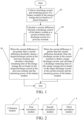
FIG. 1 is a schematic diagram of steps of a method for calculating a discharge remaining time according to an embodiment of this application. -
FIG. 2 is an overall structural block diagram of an apparatus for calculating a discharge remaining time according to an embodiment of this application. -
FIG. 3 is an overall structural block diagram of an apparatus for calculating a discharge remaining time according to another embodiment of this application. -
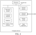
FIG. 4 is a schematic structural block diagram of a computer device according to an embodiment of this application. - The realization of the purpose, functional features and advantages of this application will be further described in conjunction with the embodiments and with reference to the accompanying drawings.
- To make purposes, technical solutions, and advantages of this application clearer, the following further describes this application in detail in conjunction with the accompanying drawings and embodiments. It should be understood that the specific embodiments described herein are intended only to explain this application and are not intended to have a limitation on the application.
- Refer to
FIG. 1 . An embodiment of this application provides a method for calculating a discharge remaining time, applied to an energy storage device, including the following steps. - S1. Collect a discharge current and remaining power of a battery module of the energy storage device based on a preset frequency.
- S2. Calculate a current difference between a discharge current of the battery module at a current moment and a discharge current at a previous moment.
- S3. When the current difference is not greater than a current difference threshold, obtain a target discharge current at the previous moment, and calculate the discharge remaining time of the energy storage device based on the target discharge current at the previous moment and the remaining power of the battery module.
- S4. When the current difference is greater than the current difference threshold, filter the discharge current at the current moment to obtain a target discharge current, and calculate the discharge remaining time of the energy storage device based on the target discharge current at the current moment and the remaining power of the battery module.
- In this embodiment, a management system of the energy storage device samples the discharge current of the battery module of the energy storage device based on the preset frequency, and after collecting a new discharge current each time, calculates the discharge remaining time based on the discharge current and the remaining power of the energy storage device. In this embodiment, a discharge remaining time at a certain moment is taken as an example to describe in detail. After sampling the discharge current at the current moment, the management system calls a discharge current at an adjacent previous moment. Then, calculate a current difference between the discharge current at the current moment and the discharge current at the previous moment (where the current difference represents an amplitude of change between discharge currents collected at two adjacent moments), and determine whether the current difference is greater than a current threshold. A specific value of the current threshold is set based on standby power consumption of the energy storage device and a sampling error range of the current during standby, and is not specified here. If the current difference between the discharge current at the current moment and the discharge current at the previous moment is not greater than the current threshold, it is considered that the discharge current sampled at the two adjacent moments has not changed, and there is no need to re-perform a first-order filtering calculation of the discharge current. At this time, the management system obtains the target discharge current at the previous moment, and calculates the target discharge current at the previous moment based on the remaining power of the energy storage device at the current moment and the target discharge current at the previous moment, to obtain a discharge remaining time. In this application, the target discharge current represents the discharge current obtained by filtering the discharge current that is output by the battery module of the energy storage device. Specifically, the target discharge current of the discharge current can be obtained by bringing the discharge current of the battery module into a filter formula.
- If the current difference between the discharge current at the current moment and the discharge current at the previous moment is greater than the current threshold, it is necessary to calculate a new target discharge current based on the discharge current at the current moment, to enable the target discharge current at the current moment after calculation to be close to an actual current as soon as possible. In this application, a first-order, second-order or high-order filtering algorithm can be used for filtering processing on the discharge current. The first-order filtering and second-order filtering will not have too much lag in data processing. In this application, the first-order filtering algorithm is used to filter the discharge current. In other embodiments, if an amplitude of change in time is required to be more stable, the second-order filtering algorithm or a higher-order filtering algorithm can be used. In this application, the management system calls the first-order filtering algorithm after modifying a filter coefficient, and calculates the target discharge current at the current moment based on the discharge current at the current moment. A general formula of the first-order filtering algorithm is Y(n)=aX(n)+(1-a)Y(n-1), where Y(n) is an output value of this filtering, Y(n-1) is an output value of last filtering, X(n) is a sampling value of this time, and a is the filter coefficient. In an actual application, a corresponding type of sampling value and filter coefficient can be set based on an actual requirement, and no specific limitation is made thereto. Finally, the management system calculates the remaining discharge time based on the target discharge current at the current moment and the remaining power of the energy storage device.
- In this embodiment, the management system performs amplitude limiting jitter processing on the sampled discharge current. When the current difference between the discharge current at the current moment and the discharge current at the previous moment is not greater than the current threshold, it is considered that the sampled discharge current has not changed, so the target discharge current at the previous moment is directly used to calculate the discharge remaining time, which is convenient and efficient. However, when the current difference between the discharge current at the current moment and the discharge current at the previous moment is greater than the current threshold, a new target discharge current (that is, the target discharge current at the current moment) is recalculated to make the filtered current close to the actual current as soon as possible, thus improving an update speed and accuracy of the discharge remaining time. It should be noted that in this application, the energy storage device includes a display module, and the display module includes a display screen that can display relevant data based on a preset display mode. After calculating the discharge remaining time of the energy storage device, the management system sends the discharge remaining time to the display module, and the display module will display the discharge remaining time based on the preset display mode. In this application, the management system collects a discharge current of a power module of the energy storage device and calculates a discharge remaining time every 250 milliseconds, and then updates a display value of the display module of the energy storage device every 1 second. In other embodiments, if there is a speed requirement for the calculation of the remaining time, a current sampling frequency and a time calculation frequency can be modified.
- Further, the step of filtering the discharge current at the current moment to obtain a target discharge current includes the following steps.
- S401. Call a first filter coefficient.
- S402. Calculate the target discharge current at the current moment based on the discharge current at the current moment, the discharge current at the previous moment, the first filter coefficient and a preset filter formula.
- The preset filter formula is: I = K 1 × I 1 + (1- K 1) × I 0, where I represents the target discharge current at the current moment, K1 represents the first filter coefficient, I1 represents the discharge current at the current moment, and I0 represents the discharge current at the previous moment.
- In this embodiment, the management system calls the first filter coefficient, and the first filter coefficient is preferably 0.95. The management system substitutes the discharge current at the current moment, the discharge current at the previous moment and the first filter coefficient into the preset filter formula for calculation, to obtain the required target discharge current at the current moment. The preset filter formula is: I = K 1 × I 1 + (1 - K 1) × I 0, where I is the target discharge current at the current moment, K1 is the first filter coefficient, I1 is the discharge current at the current moment, and I0 is the discharge current at the previous moment. In this embodiment, 0.95 is preferred as the first filter coefficient with high sensitivity, and the calculated target discharge current at the current moment is less affected by the sampled discharge current at the previous moment, which can be closer to an actual discharge current of the energy storage device to the greatest extent, thus improving the update speed and accuracy of the discharge remaining time.
- Further, after the step of calculating a target discharge current at the current moment, the method further includes the following steps.
- S403. Store the target discharge current at the current moment in a target current database, where the target current database stores a target discharge current corresponding to each moment.
- Preferably, the step of obtaining a target discharge current at the previous moment includes the following steps.
- S301. Read a target current database.
- S302. Obtain a discharge current corresponding to the previous moment in the target current database, and use the discharge current as the target discharge current.
- In this embodiment, after calculating the target discharge current at the current moment, the management system stores the target discharge current at the current moment in a preconstructed target current database. That is, after the target discharge current is calculated each time, the target discharge current is put into the target current database and stored to form a historical record, which is convenient for technicians to retrieve and view when needed. Preferably, in an actual application process, the management system reads a discharge current corresponding to a previous moment adjacent to a current moment from the target current database based on the current moment, and takes the discharge current as the target discharge current at the previous moment, and adds the subsequent discharge remaining time to the calculation.
- Further, after the step of collecting a discharge current and remaining power of a battery module of the energy storage device based on a preset frequency, the method includes the following steps.
- S5. Determine whether the discharge current of the battery module is collected for the first time.
- S6. Call a second filter coefficient if the discharge current of the battery module is collected for the first time, where the second filter coefficient is less than the first filter coefficient.
- S7. Calculate a target discharge current that is collected for the first time based on the discharge current of the battery module, the second filter coefficient and a preset filter algorithm.
- S8. Calculate the discharge remaining time of the energy storage device based on the target discharge current that is collected for the first time and the remaining power.
- In this embodiment, the management system determines whether it is the first time to collect the discharge current of the battery module of the energy storage device. If the discharge current of the battery module is collected for the first time, there is no comparison between the discharge current at the previous moment and the discharge current at the current moment. At this time, the management system calls a default second filter system to filter and calculate the discharge current, where the second filter coefficient is smaller than the first filter coefficient, and the second filter coefficient is preferably 0.05, which is less sensitive than the first filter coefficient, but a filtering result is more stable. The management system calculates the target discharge current that is collected for the first time based on the discharge current of the battery module, the second filter coefficient and the preset filter algorithm. Finally, the management system obtains a current remaining power of the energy storage device, divides the current remaining power by the target discharge current that is collected for the first time, and a resulting value is the discharge remaining time of the energy storage device at the current moment. In this embodiment, the preset filter algorithm is a first-order filter algorithm.
- Further, the step of calculating the discharge remaining time based on the target discharge current of the discharge current at the current moment includes the following steps.
- S303. Obtain the current remaining power of the energy storage device.
- S304. Calculate the discharge remaining time based on the current remaining power and the target discharge current of the discharge current at the current moment.
- In this embodiment, the management system obtains the current remaining power of the energy storage device, and substitutes the current remaining power and the target discharge current of the discharge current at the current moment into a calculation formula, to obtain a discharge remaining time. The calculation formula is

- Further, after the step of calculating the discharge remaining time of the energy storage device based on the target discharge current at the current moment and the remaining power of the battery module, the method includes the following steps.
- S9. Determine whether the discharge remaining time of the energy storage device is less than a time threshold.
- S10. Output the discharge remaining time of the energy storage device to a display interface if the discharge remaining time of the energy storage device is not less than the time threshold.
- S11. If the discharge remaining time of the energy storage device is less than the time threshold, output the discharge remaining time of the energy storage device to the display interface, and perform a reminder action.
- In this embodiment, the time threshold is set in the management system. The time threshold represents an alarm limit of the discharge remaining time of the energy storage device, and can be customized by the user as needed. Each time the management system obtains a new discharge remaining time, it will compare the discharge remaining time with the time threshold. The management system determines whether the discharge remaining time is less than the time threshold. If the discharge remaining time is not less than the time threshold, the discharge remaining time is output to the display interface for display without reminding the user, so that the user can timely understand the discharge remaining time of the energy storage device. If the discharge remaining time is less than the time threshold, in order to remind the user, the management system will not only output the discharge remaining time to the display interface, but also perform the reminder action (such as alarm sound, light flashing, etc.) to remind the user, so that the user can timely replace the energy storage device, or charge the energy storage device.
- Further, the step of outputting the discharge remaining time of the energy storage device to the display interface, and performing a reminder action includes the following steps.
- S 1101. Match a corresponding display color based on a ratio of the discharge remaining time of the energy storage device to the time threshold.
- S 1102. Output, in the display color, the discharge remaining time of the energy storage device to the display interface.
- In this embodiment, the reminder action is preferably to change the display color of the discharge remaining time. Specifically, the management system uses the time threshold as a denominator and the discharge remaining time as a numerator, to calculate the ratio of the discharge remaining time to the time threshold. Then, match the corresponding display color based on the ratio, where an internal database of the management system stores a ratio-display color mapping table, and the ratio-display color mapping table includes a plurality of sets of one-to-one corresponding ratios and display colors. Based on the ratio calculated at the current time, the management system selects the corresponding display color from the ratio-display color mapping table. Then, the discharge remaining time is output to the display interface in a matched display color for display. In this embodiment, by displaying the discharge remaining time in different display colors, the user is enabled to more intuitively understand a change of the discharge remaining time of the energy storage device.
- Further, after the step of calculating the discharge remaining time of the energy storage device based on the target discharge current at the current moment and the remaining power of the battery module, the method further includes the following steps.
- S12. Sequentially obtain discharge remaining times at several adjacent collection time points.
- S13. Respectively calculate a difference between two adjacent discharge remaining times, to obtain several time change values.
- S14. Determine, based on each time change value, whether an attenuation trend of the discharge remaining time increases.
- S15. Output prompt information if the attenuation trend of the discharge remaining time increases, where the prompt information is used for prompting the user to limit power of a discharge device connected to the energy storage device.
- In this embodiment, the management system sequentially obtains the discharge remaining times at the several adjacent collection time points from a historical records of the discharge remaining time of the energy storage device. The management system calculates the difference between the two adjacent discharge remaining times, and obtains the several time change values. The time change value represents an amplitude of change of the discharge remaining time of the energy storage device. That is, the greater the time change value, the greater the amplitude of change of the discharge remaining time between two adjacent moments. The management system determines whether the attenuation trend of the discharge remaining time increases based on each time change value sorted in order. Specifically, the management system calculates a difference between two adjacent time change values. If the difference is not 0 or greater than an amplitude threshold (where the amplitude threshold is set by a developer based on parameters of the energy storage device and the discharge device), the management system determines that the attenuation trend of the discharge remaining time increases. The management system outputs the prompt information, and the prompt information is used for prompting the user to limit the power of the discharge device connected to the energy storage device, to avoid damage to the energy storage device due to excessive discharge.
- Refer to
FIG. 2 . An embodiment of this application further provides an apparatus for calculating a discharge remaining time, applied to an energy storage device, including: - a
collection module 1, configured to collect a discharge current and remaining power of a battery module of the energy storage device based on a preset frequency; - a
first calculation module 2, configured to calculate a current difference between a discharge current of the battery module at a current moment and a discharge current at a previous moment; - a
second calculation module 3, configured to: when the current difference is not greater than a current difference threshold, obtain a target discharge current at the previous moment, and calculate the discharge remaining time of the energy storage device based on the target discharge current at the previous moment and the remaining power of the battery module; and - a
third calculation module 4, configured to: when the current difference is greater than the current difference threshold, filter the discharge current at the current moment to obtain a target discharge current, and calculate the discharge remaining time of the energy storage device based on the target discharge current at the current moment and the remaining power of the battery module. - Further, the
third calculation module 4 includes: - a call unit, configured to call a first filter coefficient; and
- a calculation unit, configured to calculate the target discharge current at the current moment based on the discharge current at the current moment, the discharge current at the previous moment, the first filter coefficient and a preset filter formula.
- The preset filter formula is: I = K 1 × I 1 + (1- K 1) × I 0, where I represents the target discharge current at the current moment, K1 represents the first filter coefficient, I1 represents the discharge current at the current moment, and I0 represents the discharge current at the previous moment.
- Further, the
third calculation module 4 further includes:
a storage unit, configured to store the target discharge current at the current moment in a target current database, where the target current database stores a target discharge current corresponding to each moment. - Further, the
second calculation module 3 includes: - a reading unit, configured to read a target current database; and
- an obtaining unit, configured to obtain a discharge current corresponding to the previous moment in the target current database, and use the discharge current as the target discharge current.
- Further, as shown in
FIG. 3 , the apparatus for calculating a discharge remaining time further includes: - a
first determination module 5, configured to determine whether the discharge current of the battery module is collected for the first time; - a
call module 6, configured to call a second filter coefficient if the discharge current of the battery module is collected for the first time, where the second filter coefficient is less than the first filter coefficient; - a
fourth calculation module 7, configured to calculate a target discharge current that is collected for the first time based on the discharge current of the battery module, the second filter coefficient and a preset filter algorithm; and - a
fifth calculation module 8, configured to calculate the discharge remaining time of the energy storage device based on the target discharge current that is collected for the first time and the remaining power. - Further, the apparatus for calculating a discharge remaining time includes:
- a
second determination module 9, configured to determine whether the discharge remaining time of the energy storage device is less than a time threshold; - an
output module 10, configured to output the discharge remaining time of the energy storage device to a display interface when it is determined that the discharge remaining time of the energy storage device is not less than the time threshold; and - a
reminder module 11, configured to: when it is determined that the discharge remaining time of the energy storage device is less than the time threshold, output the discharge remaining time of the energy storage device to the display interface, and perform a reminder action. - Further, the reminder module includes:
- a matching unit, configured to match a corresponding display color based on a ratio of the discharge remaining time of the energy storage device to the time threshold; and
- an output unit, configured to output, in the display color, the discharge remaining time of the energy storage device to the display interface.
- Further, the apparatus for calculating a discharge remaining time further includes:
- an obtaining
module 12, configured to sequentially obtain discharge remaining times at several adjacent collection time points; - a
sixth calculation module 13, configured to respectively calculate a difference between two adjacent discharge remaining times, to obtain several time change values; - a
third determination module 14, configured to determine, based on each time change value, whether an attenuation trend of the discharge remaining time increases; and - a
prompt module 15, configured to output prompt information when it is determined that the attenuation trend of the discharge remaining time increases, where the prompt information is used for prompting a user to limit power of a discharge device connected to the energy storage device. - In this embodiment, each module and unit in the apparatus is obtained to correspondingly execute each step in the foregoing method for calculating a discharge remaining time, and the specific implementation process is not described in detail here.
- This embodiment provides an apparatus for calculating a discharge remaining time. For the beneficial effects of the apparatus for calculating a discharge remaining time performing the method for calculating a discharge remaining time, reference may be made to any of the foregoing embodiments. The apparatus for calculating a discharge remaining time may be provided in the energy storage device. The apparatus for calculating a discharge remaining time may obtain a discharge current and remaining power of a battery module of the energy storage device, and calculate a discharge remaining time of the battery module accordingly.
- Refer to
FIG. 4 . Embodiments of this application further provide a computer device. The computer device may be a server, and its internal structure may be shown inFIG. 4 . The computer device includes a processor, a memory, a network interface and a database connected through a system bus. The processor designed by the computer is configured to provide computing and control capabilities. The memory of the computer device includes a non-volatile storage medium and an internal memory. The non-volatile storage medium stores an operating system, a computer program, and a database. The internal memory provides an environment for the operation of the operating system and the computer program in the non-volatile storage medium. The database of the computer device is used to store data such as a current threshold. The network interface of the computer device is used to communicate with an external terminal through a network connection. The computer program is executed by the processor to implement the method for calculating a discharge remaining time provided by any of the foregoing embodiments, which is applicable to the energy storage device. - An embodiment of this application further provides a computer-readable storage medium. A computer program is stored on the computer-readable storage medium. When the computer program is executed by a processor, the method for calculating a discharge remaining time provided by any of the foregoing embodiments is implemented. A person of ordinary skill in the art may understand that all or some of the processes of the method embodiments may be implemented by instructing relevant hardware through a computer program. The computer program may be stored in a non-volatile computer-readable storage medium. When executed, the computer program may include the processes of the foregoing method embodiments. Any references to memories, storage, databases or other media provided in this application and used in embodiments may include a non-volatile and/or volatile memory. The non-volatile memory may include a read-only memory (ROM), a programmable ROM (PROM), an electrically programmable ROM (EPROM), an electrically erasable programmable ROM (EEPROM), or a flash memory. The volatile memory may include a random access memory (RAM) or an external cache. As an illustration rather than a limitation, the RAM is available in many forms, such as a static RAM (SRAM), a dynamic RAM (DRAM), a synchronous DRAM (SDRAM), a double data rate SDRAM (DDRSDRAM), an enhanced SDRAM (ESDRAM), a synchlink (Synchlink) DRAM (SLDRAM), a rambus (Rambus) direct RAM (RDRAM), a direct rambus dynamic RAM (DRDRAM), and a rambus dynamic RAM (RDRAM).
- It should be noted that the terms "include", "comprise", or any other variation thereof in this specification is intended to cover a non-exclusive inclusion, such that processes, apparatuses, first objects or methods including a series of elements not only include those elements, but also other elements not expressly listed or elements inherent to the processes, apparatuses, first objects or methods. Without more limitations, elements defined by the sentence "including one ..." does not exclude that there are still other same elements in the processes, apparatuses, first objects, or methods including the elements.
- The above are only preferred embodiments of this application, and do not limit the patent scope of this application. Any equivalent structure or equivalent process transformation that is made using the contents of the specification and the accompanying drawings of this application, or directly or indirectly used in other related technical fields is equally included in the patent protection scope of this application.
Claims (10)
- A method for calculating a discharge remaining time, applied to an energy storage device, comprising:collecting a discharge current and remaining power of a battery module of the energy storage device based on a preset frequency;calculating a current difference between a discharge current of the battery module at a current moment and a discharge current at a previous moment;when the current difference is not greater than a current difference threshold, obtaining a target discharge current at the previous moment, and calculating the discharge remaining time of the energy storage device based on the target discharge current at the previous moment and the remaining power of the battery module; andwhen the current difference is greater than the current difference threshold, filtering the discharge current at the current moment to obtain a target discharge current, and calculating the discharge remaining time of the energy storage device based on the target discharge current at the current moment and the remaining power of the battery module.
- The method for calculating a discharge remaining time according to claim 1, wherein the step of filtering the discharge current at the current moment to obtain a target discharge current comprises:calling a first filter coefficient; andcalculating the target discharge current at the current moment based on the discharge current at the current moment, the discharge current at the previous moment, the first filter coefficient and a preset filter formula, whereinthe preset filter formula is: I = K 1 × I 1 + (1- K 1) × I 0, wherein I represents the target discharge current at the current moment, K1 represents the first filter coefficient, I1 represents the discharge current at the current moment, and I0 represents the discharge current at the previous moment.
- The method for calculating a discharge remaining time according to claim 2, wherein after the step of calculating the target discharge current at the current moment, the method further comprises:
storing the target discharge current at the current moment in a target current database, wherein the target current database stores a target discharge current corresponding to each moment. - The method for calculating a discharge remaining time according to claim 1, wherein the step of obtaining a target discharge current at the previous moment comprises:reading a target current database; andobtaining a discharge current corresponding to the previous moment in the target current database, and using the discharge current as the target discharge current.
- The method for calculating a discharge remaining time according to claim 2, wherein after the step of collecting a discharge current and remaining power of a battery module of the energy storage device based on a preset frequency, the method further comprises:determining whether the discharge current of the battery module is collected for the first time;calling a second filter coefficient if the discharge current of the battery module is collected for the first time, wherein the second filter coefficient is less than the first filter coefficient;calculating a target discharge current that is collected for the first time based on the discharge current of the battery module, the second filter coefficient and a preset filter algorithm; andcalculating the discharge remaining time of the energy storage device based on the target discharge current that is collected for the first time and the remaining power.
- The method for calculating a discharge remaining time according to claim 1, wherein after the step of calculating the discharge remaining time of the energy storage device based on the target discharge current at the current moment and the remaining power of the battery module, the method comprises:determining whether the discharge remaining time of the energy storage device is less than a time threshold;outputting the discharge remaining time of the energy storage device to a display interface if the discharge remaining time of the energy storage device is not less than the time threshold; andif the discharge remaining time of the energy storage device is less than the time threshold, outputting the discharge remaining time of the energy storage device to the display interface, and performing a reminder action.
- The method for calculating a discharge remaining time according to claim 6, wherein the step of outputting the discharge remaining time of the energy storage device to the display interface, and performing a reminder action comprises:matching a corresponding display color based on a ratio of the discharge remaining time of the energy storage device to the time threshold; andoutputting, in the display color, the discharge remaining time of the energy storage device to the display interface.
- The method for calculating a discharge remaining time according to claim 1, wherein after the step of calculating the discharge remaining time of the energy storage device based on the target discharge current at the current moment and the remaining power of the battery module, the method further comprises:sequentially obtaining discharge remaining times at several adjacent collection time points;respectively calculating a difference between two adjacent discharge remaining times, to obtain several time change values;determining, based on each time change value, whether an attenuation trend of the discharge remaining time increases; andoutputting prompt information if the attenuation trend of the discharge remaining time increases, wherein the prompt information is used for prompting a user to limit power of a discharge device connected to the energy storage device.
- An apparatus for calculating a discharge remaining time, applied to an energy storage device, comprising:a collection module, configured to collect a discharge current and remaining power of a battery module of the energy storage device based on a preset frequency;a first calculation module, configured to calculate a current difference between a discharge current of the battery module at a current moment and a discharge current at a previous moment;a second calculation module, configured to: when the current difference is not greater than a current difference threshold, obtain a target discharge current at the previous moment, and calculate the discharge remaining time of the energy storage device based on the target discharge current at the previous moment and the remaining power of the battery module; anda third calculation module, configured to: when the current difference is greater than the current difference threshold, filter the discharge current at the current moment to obtain a target discharge current, and calculate the discharge remaining time of the energy storage device based on the target discharge current at the current moment and the remaining power of the battery module.
- A computer device, comprising a memory and a processor, wherein the memory stores a computer program, and when executing the computer program, the processor implements the steps of the method according to any one of claims 1 to 8.
Applications Claiming Priority (2)
| Application Number | Priority Date | Filing Date | Title |
|---|---|---|---|
| CN202110763349.0A CN113640691B (en) | 2021-07-06 | 2021-07-06 | Method and device for calculating discharge remaining time and computer equipment |
| PCT/CN2022/093236 WO2023279856A1 (en) | 2021-07-06 | 2022-05-17 | Method and apparatus for calculating remaining discharge time, and computer device |
Publications (2)
| Publication Number | Publication Date |
|---|---|
| EP4354166A1 true EP4354166A1 (en) | 2024-04-17 |
| EP4354166A4 EP4354166A4 (en) | 2024-10-23 |
Family
ID=78416752
Family Applications (1)
| Application Number | Title | Priority Date | Filing Date |
|---|---|---|---|
| EP22836612.6A Pending EP4354166A4 (en) | 2021-07-06 | 2022-05-17 | METHOD AND APPARATUS FOR CALCULATING REMAINING DISCHARGE TIME AND COMPUTER DEVICE |
Country Status (6)
| Country | Link |
|---|---|
| US (1) | US20240151775A1 (en) |
| EP (1) | EP4354166A4 (en) |
| JP (1) | JP7631561B2 (en) |
| KR (1) | KR102864191B1 (en) |
| CN (1) | CN113640691B (en) |
| WO (1) | WO2023279856A1 (en) |
Families Citing this family (8)
| Publication number | Priority date | Publication date | Assignee | Title |
|---|---|---|---|---|
| CN113640691B (en) * | 2021-07-06 | 2022-02-22 | 深圳市正浩创新科技股份有限公司 | Method and device for calculating discharge remaining time and computer equipment |
| CN114301426B (en) * | 2021-11-17 | 2025-10-24 | 潍柴动力股份有限公司 | Clutch position signal filtering method, device, clutch and vehicle |
| CN115408446A (en) * | 2022-09-05 | 2022-11-29 | 珠海格力电器股份有限公司 | Calculation method, device, electronic equipment and storage medium for total power consumption |
| CN116137532B (en) * | 2023-02-06 | 2023-09-08 | 广芯微电子(广州)股份有限公司 | Method, device, equipment and medium for improving sampling value precision of analog-to-digital converter |
| CN116500468B (en) * | 2023-06-26 | 2023-09-12 | 浙江金开物联网科技有限公司 | Electric quantity calculation method of storage battery, battery management system and storage battery car |
| CN116699430B (en) * | 2023-08-04 | 2023-11-21 | 上海泰矽微电子有限公司 | Battery residual capacity and state of charge synchronization method, electric equipment and medium |
| CN118483605B (en) * | 2024-05-17 | 2024-12-17 | 惠州市乐亿通科技股份有限公司 | Method and device for determining remaining chargeable and dischargeable time length of battery, and electronic equipment |
| CN118676985B (en) * | 2024-06-14 | 2025-05-16 | 深圳市健网科技有限公司 | Distributed modularized energy storage device |
Family Cites Families (38)
| Publication number | Priority date | Publication date | Assignee | Title |
|---|---|---|---|---|
| JPH0232276A (en) * | 1988-07-22 | 1990-02-02 | Yuasa Battery Co Ltd | How to detect battery life |
| JPH04348290A (en) * | 1991-01-28 | 1992-12-03 | Matsushita Electric Works Ltd | Battery type electric apparatus |
| JPH06119941A (en) * | 1992-09-30 | 1994-04-28 | Japan Storage Battery Co Ltd | Method for detecting remaining battery discharge time and remaining capacity |
| US5631540A (en) * | 1994-11-23 | 1997-05-20 | Lucent Technologies Inc. | Method and apparatus for predicting the remaining capacity and reserve time of a battery on discharge |
| KR19980050341A (en) * | 1996-12-20 | 1998-09-15 | 윤원석 | How to display battery remaining time |
| JP2001051030A (en) * | 1999-08-09 | 2001-02-23 | Hitachi Maxell Ltd | Rechargeable battery or rechargeable battery pack |
| JP2002050408A (en) * | 2000-08-07 | 2002-02-15 | Hitachi Maxell Ltd | Rechargeable battery, rechargeable battery pack, and method for calculating remaining amount of rechargeable battery |
| JP5395556B2 (en) * | 2009-07-29 | 2014-01-22 | パナソニック株式会社 | Remaining time calculation device and remaining time calculation method |
| TWI404964B (en) * | 2010-04-22 | 2013-08-11 | 盈正豫順電子股份有限公司 | Battery discharge residual time estimation method |
| CN101900793B (en) | 2010-07-30 | 2013-02-27 | 盈正豫顺电子股份有限公司 | Estimation method of battery discharge residual time |
| CN102082867B (en) * | 2010-12-13 | 2013-08-14 | 惠州Tcl移动通信有限公司 | Method, system and mobile phone capable of informing users of supportable talk time |
| CN102655549B (en) | 2012-01-31 | 2014-03-12 | 吕林波 | Method for estimating remaining time and capacity of battery |
| US10664562B2 (en) * | 2013-02-24 | 2020-05-26 | Fairchild Semiconductor Corporation and University of Connecticut | Battery state of charge tracking, equivalent circuit selection and benchmarking |
| CN104316882A (en) * | 2014-07-08 | 2015-01-28 | 北京鸿智电通科技有限公司 | Method and device for detecting residual capacity of mobile power supply |
| CN105527574A (en) * | 2014-09-30 | 2016-04-27 | 百纳德(扬州)电能系统有限公司 | Novel battery patrol instrument suitable for UPS |
| EP3069923B1 (en) * | 2015-03-18 | 2018-02-28 | IVECO S.p.A. | Estimation method of a residual electric vehicle range |
| DE102015212328B4 (en) * | 2015-07-01 | 2019-03-21 | Dialog Semiconductor (Uk) Limited | Battery state of charge measurement circuit |
| CN104977545B (en) * | 2015-08-03 | 2017-12-19 | 电子科技大学 | The state-of-charge method of estimation and system of a kind of electrokinetic cell |
| CN106603037A (en) * | 2015-10-19 | 2017-04-26 | 沈阳新松机器人自动化股份有限公司 | Smooth data processing method and system |
| JP6361643B2 (en) * | 2015-12-15 | 2018-07-25 | 横河電機株式会社 | Energy storage service system |
| CN108432081A (en) * | 2015-12-31 | 2018-08-21 | 深圳市大疆创新科技有限公司 | Method and system for managing battery component |
| CN106501736B (en) * | 2017-01-04 | 2019-08-09 | 山东谦恒电子科技有限公司 | Internal resistance of cell evaluation method and device |
| CN109270467A (en) * | 2017-07-18 | 2019-01-25 | 美的智慧家居科技有限公司 | Battery power detecting method and device for equipment |
| KR102459982B1 (en) * | 2017-09-26 | 2022-10-27 | 삼성전자주식회사 | Battery managing apparatus connecting batteries to electric devices based on a state of charge of the batteries and a method thereof |
| CN110133506B (en) * | 2018-02-09 | 2021-03-12 | 宝山钢铁股份有限公司 | Device and method for calculating remaining service time of lithium battery |
| CN108896927B (en) | 2018-07-20 | 2020-10-13 | 深圳市道通智能航空技术有限公司 | Estimation method and device of remaining flight time of aircraft, battery and aircraft |
| CN108896928B (en) * | 2018-07-20 | 2020-12-08 | 深圳市道通智能航空技术有限公司 | Estimation method and device of battery remaining time, battery cell, battery and aircraft |
| KR102578585B1 (en) * | 2019-03-19 | 2023-09-15 | 주식회사 엘지에너지솔루션 | Apparatus and method for checking battery safety |
| US11525862B2 (en) * | 2019-04-08 | 2022-12-13 | Ningde Amperex Technology Limited | Methods, storage media, and electronic devices for calculating short-circuit current of battery |
| CN110047260A (en) * | 2019-04-19 | 2019-07-23 | 航天云网数据研究院(江苏)有限公司 | A kind of data gathering algorithm |
| CN110470995B (en) * | 2019-07-19 | 2021-08-10 | 科华恒盛股份有限公司 | Method and system for acquiring remaining discharge time of battery and terminal equipment |
| CN112858924B (en) * | 2019-11-28 | 2023-06-13 | 比亚迪股份有限公司 | Power battery remaining energy estimation method, device, vehicle and storage medium |
| CN111064174A (en) * | 2019-12-24 | 2020-04-24 | 追觅科技(上海)有限公司 | Voltage adaptation method, device and storage medium |
| CN111426965B (en) * | 2020-05-15 | 2022-05-06 | 深圳英集芯科技股份有限公司 | Method for calculating electric quantity of battery |
| CN112421567A (en) * | 2020-07-28 | 2021-02-26 | 深圳市正浩创新科技有限公司 | Leakage protection method and system based on micro energy storage system |
| CN112098856B (en) * | 2020-08-26 | 2023-08-18 | 贵州电网有限责任公司 | Method for dynamically measuring endurance time of storage battery pack of transformer substation |
| CN112748347B (en) * | 2020-12-30 | 2023-08-25 | 北京二郎神科技有限公司 | Battery electric quantity acquisition method and device, storage medium and electronic equipment |
| CN113640691B (en) * | 2021-07-06 | 2022-02-22 | 深圳市正浩创新科技股份有限公司 | Method and device for calculating discharge remaining time and computer equipment |
-
2021
- 2021-07-06 CN CN202110763349.0A patent/CN113640691B/en active Active
-
2022
- 2022-05-17 WO PCT/CN2022/093236 patent/WO2023279856A1/en not_active Ceased
- 2022-05-17 KR KR1020237040280A patent/KR102864191B1/en active Active
- 2022-05-17 EP EP22836612.6A patent/EP4354166A4/en active Pending
- 2022-05-17 JP JP2023571972A patent/JP7631561B2/en active Active
-
2024
- 2024-01-04 US US18/404,595 patent/US20240151775A1/en active Pending
Also Published As
| Publication number | Publication date |
|---|---|
| CN113640691B (en) | 2022-02-22 |
| KR102864191B1 (en) | 2025-09-24 |
| CN113640691A (en) | 2021-11-12 |
| WO2023279856A1 (en) | 2023-01-12 |
| JP7631561B2 (en) | 2025-02-18 |
| KR20230174757A (en) | 2023-12-28 |
| US20240151775A1 (en) | 2024-05-09 |
| JP2024521727A (en) | 2024-06-04 |
| EP4354166A4 (en) | 2024-10-23 |
Similar Documents
| Publication | Publication Date | Title |
|---|---|---|
| EP4354166A1 (en) | Method and apparatus for calculating remaining discharge time, and computer device | |
| CN115616421B (en) | A battery health status estimation method, system, device and medium | |
| West et al. | Bayesian forecasting and dynamic models | |
| EP2649666B1 (en) | Method for ascertaining operating parameters of a battery, battery management system, and battery | |
| EP4235338A1 (en) | Method and apparatus for predicting energy consumption of commercial electric vehicle, and computer device | |
| EP3542173A1 (en) | Determining a state of health of a battery and providing an alert | |
| EP4737924A1 (en) | Battery state-of-health estimation method, electronic device and computer-readable storage medium | |
| CN110110916A (en) | A kind of prediction technique and system of the medical amount of hospital outpatient | |
| EP4404327A1 (en) | Battery management method and apparatus, and computer-readable storage medium | |
| CN118415652A (en) | Situational awareness classification system and method based on β-electroencephalogram features in human-machine co-driving | |
| CN107861082B (en) | Calibration interval determining method and device of electronic measuring equipment | |
| CN114994542B (en) | Method and device for estimating open-circuit voltage of battery, electronic equipment and readable storage medium | |
| CN116466256A (en) | A battery monitoring method, device, vehicle and storage medium | |
| CN120448490A (en) | Intelligent question-answering system and method | |
| CN112046784B (en) | Unmanned aerial vehicle positioner endurance time analysis method and device and unmanned aerial vehicle positioner | |
| CN114487849A (en) | Battery running state display method and system | |
| EP4464534A1 (en) | Method and system for predicting insufficient voltage probability of vehicle, and cloud server | |
| CN112613632A (en) | Power prediction model establishing method, prediction method and device and electronic equipment | |
| FI20245577A1 (en) | Procedure for recalibrating the state of charge of multi-battery systems | |
| US12216171B2 (en) | Estimation method, estimation system, and non-transitory computer-readable recording medium | |
| CN116929437B (en) | Sensor information identification method and device applied to cell formation component system | |
| CN113722470B (en) | Information prompting method, device, equipment and storage medium | |
| US20240120760A1 (en) | Method for charging an electrical energy storage device, electrical energy management system and computer program product for carrying out the method, and use thereof | |
| EP4071628B1 (en) | Data update method and apparatus for refrigerator freshness preservation model, and storage medium | |
| CN113933717B (en) | Method and device for obtaining electric quantity of battery, battery and electronic equipment |
Legal Events
| Date | Code | Title | Description |
|---|---|---|---|
| STAA | Information on the status of an ep patent application or granted ep patent |
Free format text: STATUS: THE INTERNATIONAL PUBLICATION HAS BEEN MADE |
|
| PUAI | Public reference made under article 153(3) epc to a published international application that has entered the european phase |
Free format text: ORIGINAL CODE: 0009012 |
|
| STAA | Information on the status of an ep patent application or granted ep patent |
Free format text: STATUS: REQUEST FOR EXAMINATION WAS MADE |
|
| 17P | Request for examination filed |
Effective date: 20240109 |
|
| AK | Designated contracting states |
Kind code of ref document: A1 Designated state(s): AL AT BE BG CH CY CZ DE DK EE ES FI FR GB GR HR HU IE IS IT LI LT LU LV MC MK MT NL NO PL PT RO RS SE SI SK SM TR |
|
| DAV | Request for validation of the european patent (deleted) | ||
| DAX | Request for extension of the european patent (deleted) | ||
| A4 | Supplementary search report drawn up and despatched |
Effective date: 20240924 |
|
| RIC1 | Information provided on ipc code assigned before grant |
Ipc: G01R 31/382 20190101ALI20240918BHEP Ipc: G01R 31/3832 20190101ALI20240918BHEP Ipc: G01R 31/36 20200101ALI20240918BHEP Ipc: G01R 31/367 20190101ALI20240918BHEP Ipc: G01R 31/387 20190101ALI20240918BHEP Ipc: G01R 31/385 20190101ALI20240918BHEP Ipc: G01R 31/396 20190101AFI20240918BHEP |