EP4354217A1 - Source de rayonnement et procédé de production d'un rayonnement électromagnétique à plusieurs fréquences - Google Patents
Source de rayonnement et procédé de production d'un rayonnement électromagnétique à plusieurs fréquences Download PDFInfo
- Publication number
- EP4354217A1 EP4354217A1 EP22201560.4A EP22201560A EP4354217A1 EP 4354217 A1 EP4354217 A1 EP 4354217A1 EP 22201560 A EP22201560 A EP 22201560A EP 4354217 A1 EP4354217 A1 EP 4354217A1
- Authority
- EP
- European Patent Office
- Prior art keywords
- radiation
- initial
- power
- frequency
- source
- Prior art date
- Legal status (The legal status is an assumption and is not a legal conclusion. Google has not performed a legal analysis and makes no representation as to the accuracy of the status listed.)
- Pending
Links
Images

Classifications
-
- H—ELECTRICITY
- H01—ELECTRIC ELEMENTS
- H01S—DEVICES USING THE PROCESS OF LIGHT AMPLIFICATION BY STIMULATED EMISSION OF RADIATION [LASER] TO AMPLIFY OR GENERATE LIGHT; DEVICES USING STIMULATED EMISSION OF ELECTROMAGNETIC RADIATION IN WAVE RANGES OTHER THAN OPTICAL
- H01S5/00—Semiconductor lasers
- H01S5/005—Optical components external to the laser cavity, specially adapted therefor, e.g. for homogenisation or merging of the beams or for manipulating laser pulses, e.g. pulse shaping
- H01S5/0092—Optical components external to the laser cavity, specially adapted therefor, e.g. for homogenisation or merging of the beams or for manipulating laser pulses, e.g. pulse shaping for nonlinear frequency conversion, e.g. second harmonic generation [SHG] or sum- or difference-frequency generation outside the laser cavity
-
- G—PHYSICS
- G02—OPTICS
- G02F—OPTICAL DEVICES OR ARRANGEMENTS FOR THE CONTROL OF LIGHT BY MODIFICATION OF THE OPTICAL PROPERTIES OF THE MEDIA OF THE ELEMENTS INVOLVED THEREIN; NON-LINEAR OPTICS; FREQUENCY-CHANGING OF LIGHT; OPTICAL LOGIC ELEMENTS; OPTICAL ANALOGUE/DIGITAL CONVERTERS
- G02F1/00—Devices or arrangements for the control of the intensity, colour, phase, polarisation or direction of light arriving from an independent light source, e.g. switching, gating or modulating; Non-linear optics
- G02F1/35—Non-linear optics
- G02F1/39—Non-linear optics for parametric generation or amplification of light, infrared or ultraviolet waves
- G02F1/392—Parametric amplification
-
- G—PHYSICS
- G02—OPTICS
- G02F—OPTICAL DEVICES OR ARRANGEMENTS FOR THE CONTROL OF LIGHT BY MODIFICATION OF THE OPTICAL PROPERTIES OF THE MEDIA OF THE ELEMENTS INVOLVED THEREIN; NON-LINEAR OPTICS; FREQUENCY-CHANGING OF LIGHT; OPTICAL LOGIC ELEMENTS; OPTICAL ANALOGUE/DIGITAL CONVERTERS
- G02F1/00—Devices or arrangements for the control of the intensity, colour, phase, polarisation or direction of light arriving from an independent light source, e.g. switching, gating or modulating; Non-linear optics
- G02F1/35—Non-linear optics
- G02F1/3501—Constructional details or arrangements of non-linear optical devices, e.g. shape of non-linear crystals
- G02F1/3507—Arrangements comprising two or more nonlinear optical devices
-
- G—PHYSICS
- G02—OPTICS
- G02F—OPTICAL DEVICES OR ARRANGEMENTS FOR THE CONTROL OF LIGHT BY MODIFICATION OF THE OPTICAL PROPERTIES OF THE MEDIA OF THE ELEMENTS INVOLVED THEREIN; NON-LINEAR OPTICS; FREQUENCY-CHANGING OF LIGHT; OPTICAL LOGIC ELEMENTS; OPTICAL ANALOGUE/DIGITAL CONVERTERS
- G02F1/00—Devices or arrangements for the control of the intensity, colour, phase, polarisation or direction of light arriving from an independent light source, e.g. switching, gating or modulating; Non-linear optics
- G02F1/35—Non-linear optics
- G02F1/353—Frequency conversion, i.e. wherein a light beam is generated with frequency components different from those of the incident light beams
-
- G—PHYSICS
- G02—OPTICS
- G02F—OPTICAL DEVICES OR ARRANGEMENTS FOR THE CONTROL OF LIGHT BY MODIFICATION OF THE OPTICAL PROPERTIES OF THE MEDIA OF THE ELEMENTS INVOLVED THEREIN; NON-LINEAR OPTICS; FREQUENCY-CHANGING OF LIGHT; OPTICAL LOGIC ELEMENTS; OPTICAL ANALOGUE/DIGITAL CONVERTERS
- G02F1/00—Devices or arrangements for the control of the intensity, colour, phase, polarisation or direction of light arriving from an independent light source, e.g. switching, gating or modulating; Non-linear optics
- G02F1/35—Non-linear optics
- G02F1/353—Frequency conversion, i.e. wherein a light beam is generated with frequency components different from those of the incident light beams
- G02F1/3544—Particular phase matching techniques
- G02F1/3546—Active phase matching, e.g. by electro- or thermo-optic tuning
-
- G—PHYSICS
- G02—OPTICS
- G02F—OPTICAL DEVICES OR ARRANGEMENTS FOR THE CONTROL OF LIGHT BY MODIFICATION OF THE OPTICAL PROPERTIES OF THE MEDIA OF THE ELEMENTS INVOLVED THEREIN; NON-LINEAR OPTICS; FREQUENCY-CHANGING OF LIGHT; OPTICAL LOGIC ELEMENTS; OPTICAL ANALOGUE/DIGITAL CONVERTERS
- G02F1/00—Devices or arrangements for the control of the intensity, colour, phase, polarisation or direction of light arriving from an independent light source, e.g. switching, gating or modulating; Non-linear optics
- G02F1/35—Non-linear optics
- G02F1/355—Non-linear optics characterised by the materials used
- G02F1/3551—Crystals
-
- H—ELECTRICITY
- H01—ELECTRIC ELEMENTS
- H01S—DEVICES USING THE PROCESS OF LIGHT AMPLIFICATION BY STIMULATED EMISSION OF RADIATION [LASER] TO AMPLIFY OR GENERATE LIGHT; DEVICES USING STIMULATED EMISSION OF ELECTROMAGNETIC RADIATION IN WAVE RANGES OTHER THAN OPTICAL
- H01S3/00—Lasers, i.e. devices using stimulated emission of electromagnetic radiation in the infrared, visible or ultraviolet wave range
- H01S3/10—Controlling the intensity, frequency, phase, polarisation or direction of the emitted radiation, e.g. switching, gating, modulating or demodulating
- H01S3/13—Stabilisation of laser output parameters, e.g. frequency or amplitude
- H01S3/1305—Feedback control systems
-
- H—ELECTRICITY
- H01—ELECTRIC ELEMENTS
- H01S—DEVICES USING THE PROCESS OF LIGHT AMPLIFICATION BY STIMULATED EMISSION OF RADIATION [LASER] TO AMPLIFY OR GENERATE LIGHT; DEVICES USING STIMULATED EMISSION OF ELECTROMAGNETIC RADIATION IN WAVE RANGES OTHER THAN OPTICAL
- H01S3/00—Lasers, i.e. devices using stimulated emission of electromagnetic radiation in the infrared, visible or ultraviolet wave range
- H01S3/10—Controlling the intensity, frequency, phase, polarisation or direction of the emitted radiation, e.g. switching, gating, modulating or demodulating
- H01S3/13—Stabilisation of laser output parameters, e.g. frequency or amplitude
- H01S3/139—Stabilisation of laser output parameters, e.g. frequency or amplitude by controlling the mutual position or the reflecting properties of the reflectors of the cavity, e.g. by controlling the cavity length
-
- H—ELECTRICITY
- H01—ELECTRIC ELEMENTS
- H01S—DEVICES USING THE PROCESS OF LIGHT AMPLIFICATION BY STIMULATED EMISSION OF RADIATION [LASER] TO AMPLIFY OR GENERATE LIGHT; DEVICES USING STIMULATED EMISSION OF ELECTROMAGNETIC RADIATION IN WAVE RANGES OTHER THAN OPTICAL
- H01S5/00—Semiconductor lasers
- H01S5/04—Processes or apparatus for excitation, e.g. pumping, e.g. by electron beams
- H01S5/041—Optical pumping
-
- H—ELECTRICITY
- H01—ELECTRIC ELEMENTS
- H01S—DEVICES USING THE PROCESS OF LIGHT AMPLIFICATION BY STIMULATED EMISSION OF RADIATION [LASER] TO AMPLIFY OR GENERATE LIGHT; DEVICES USING STIMULATED EMISSION OF ELECTROMAGNETIC RADIATION IN WAVE RANGES OTHER THAN OPTICAL
- H01S5/00—Semiconductor lasers
- H01S5/06—Arrangements for controlling the laser output parameters, e.g. by operating on the active medium
- H01S5/0604—Arrangements for controlling the laser output parameters, e.g. by operating on the active medium comprising a non-linear region, e.g. generating harmonics of the laser frequency
- H01S5/0605—Self doubling, e.g. lasing and frequency doubling by the same active medium
-
- G—PHYSICS
- G02—OPTICS
- G02F—OPTICAL DEVICES OR ARRANGEMENTS FOR THE CONTROL OF LIGHT BY MODIFICATION OF THE OPTICAL PROPERTIES OF THE MEDIA OF THE ELEMENTS INVOLVED THEREIN; NON-LINEAR OPTICS; FREQUENCY-CHANGING OF LIGHT; OPTICAL LOGIC ELEMENTS; OPTICAL ANALOGUE/DIGITAL CONVERTERS
- G02F2201/00—Constructional arrangements not provided for in groups G02F1/00 - G02F7/00
- G02F2201/16—Constructional arrangements not provided for in groups G02F1/00 - G02F7/00 series; tandem
Definitions
- the present invention relates to a radiation source for generating electromagnetic radiation with a plurality of frequencies, wherein the radiation source has an initial source, a non-linear optical frequency converter, a conversion detector and a controller.
- the initial source is set up such that, when the radiation source is operating, it generates electromagnetic initial radiation with an initial center frequency.
- the non-linear optical frequency converter for example an optical parametric oscillator, has a converter resonator that is resonant for the initial radiation and has a coupling mirror that is partially transparent to the initial radiation, and a non-linear optical crystal arranged in the converter resonator.
- the frequency converter is arranged in a beam path of the initial radiation, so that when the radiation source is operating, the initial radiation is coupled into the converter resonator by the coupling mirror.
- the frequency converter is set up such that, when the radiation source is operating, it generates radiation converted from the initial radiation with a converted frequency, wherein the converted frequency is different from a frequency of the initial radiation.
- the converter resonator has an actuator, the actuator being arranged and configured such that a resonance frequency of the converter resonator can be tuned by means of the actuator depending on a conversion control signal.
- the conversion detector is arranged in a beam path of the converted radiation or in the beam path of the initial radiation in the beam direction after the coupling mirror, so that the conversion detector detects a measure of the power of the converted radiation when the radiation source is operating and outputs a conversion measurement signal representing the measure of the power of the converted radiation.
- the controller is connected to the conversion detector such that the controller receives the conversion measurement signal when the radiation source is operating, the controller being connected to the actuator such that the actuator receives the conversion control signal from the controller when the radiation source is operating.
- the controller is configured such that, when the radiation source is operating in a first operating mode, it generates the conversion control signal as a function of the conversion measurement signal such that the resonance frequency is controlled such that it follows the signal center frequency.
- the present invention further relates to a method for generating electromagnetic radiation with a plurality of frequencies, the method comprising the steps of: generating initial electromagnetic radiation with an initial center frequency with an initial radiation source, coupling the initial radiation through a coupling mirror into a converter resonator resonant for the initial radiation, generating converted radiation with a converted frequency from the initial radiation in a nonlinear optical crystal arranged in the converter resonator, the converted frequency being different from a frequency of the initial radiation, detecting a measure of the power of the converted radiation with a conversion detector arranged in a beam path of the converted radiation or in the beam path of the initial radiation in the beam direction after the coupling mirror, and in a first operating mode, controlling a resonance frequency of the converter resonator depending on the measure of the power of the converted radiation so that the resonance frequency follows the initial center frequency.
- Radiation sources are known from the prior art that attempt to provide the greatest possible wavelength coverage of the generated electromagnetic radiation.
- a pump laser to pump an optically parametric oscillator, so that in addition to the frequency of the electromagnetic pump radiation, the signal and idler radiation of the optically parametric oscillator with a signal center frequency and idler center frequency that are different from the frequency of the pump radiation are also available.
- Such an arrangement of pump laser and optically parametric oscillator is referred to as an initial source in the sense of the present application.
- converted radiation is generated from the signal radiation by a further nonlinear process in a nonlinear optical frequency converter, for example by generating the second harmonic in a nonlinear optical crystal, such a radiation source can address four different wavelengths.
- a non-linear optical crystal is arranged in a converter resonator that is resonant for the initial radiation for the non-linear optical frequency converter.
- the power of the converted radiation generated in the frequency converter from the initial radiation then depends on a large number of parameters.
- a key factor is the difference between the initial center frequency and the resonance frequency of the converter resonator. If the initial center frequency changes while If the resonance frequency of the converter resonator remains constant, the power of the converted radiation also changes.
- the control of a radiation source for generating electromagnetic radiation with a plurality of frequencies of the type mentioned at the beginning is set up in such a way that the control can be selected to switch between the first operating mode and a second operating mode during operation of the radiation source.
- the control is set up in such a way that in the second operating mode it generates the conversion control signal in such a way that the power of the converted radiation is regulated in such a way that either the power of the converted radiation has a smaller relative temporal fluctuation than the power of the Initial radiation in the beam direction in front of the coupling mirror or the power of the initial radiation in the beam direction after the coupling mirror has a smaller relative temporal fluctuation than the power of the initial radiation in the beam direction in front of the coupling mirror.
- the basic idea of the present invention is to design the radiation source so that it can be switched over by a user, so that the user can select whether the frequency converter is controlled in such a way that either the maximum power of the converted radiation is available at any time, but at the cost of a larger relative power fluctuation, or the converted radiation or the initial radiation in the beam direction behind the coupling mirror is available with a reduced relative power fluctuation, but with a lower absolute power.
- the initial radiation in the beam direction in front of the coupling mirror i.e. in the beam direction in front of the converter resonator, serves as a comparison standard for the relative temporal fluctuation of the power of either the converted radiation or the initial radiation in the beam direction behind the coupling mirror.
- the second operating module it is possible to either reduce the relative temporal fluctuation of the power of the converted radiation or the relative temporal fluctuation of the initial radiation.
- the power consumption of initial radiation by the frequency converter depends on how large the actual conversion of the initial radiation in the frequency converter into the converted radiation is. Therefore, by regulating the power of the converted radiation via the resonance frequency of the conversion resonator, as an alternative to the power of the converted radiation itself, a temporal fluctuation in the power of the output radiation reflected by the coupling mirror of the conversion resonator can also be reduced.
- the frequency converter then serves as a kind of "noise eater" for the output radiation.
- the coupling mirror is arranged such that the initial radiation reflected at the coupling mirror and not transmitted into the converter resonator is reflected at the coupling mirror at an angle other than 90°.
- the nonlinear optical frequency converter is selected from a frequency doubler, a device for generating sum frequencies, a device for generating difference frequencies, a device for providing an optically parametric process or a device for 4-wave mixing.
- the nonlinear optical frequency converter is a frequency doubler, in which case the nonlinear optical crystal is a doubler crystal, so that the converted frequency is equal to twice the frequency of the output radiation.
- the frequency converter according to the invention always comprises a converter resonator which is resonant for the initial radiation and thus leads to an increase in the conversion efficiency in the nonlinear optical crystal.
- the coupling mirror through which the initial radiation is coupled into the converter resonator is a mirror that is partially transparent to the initial radiation.
- a partially transparent mirror means that a portion of the initial radiation is always reflected by the coupling mirror.
- the initial source comprises a pump laser and an optically parametric oscillator
- the pump laser is configured such that it generates electromagnetic pump radiation during operation of the radiation source
- the optically parametric oscillator (OPO) is arranged in a beam path of the pump radiation
- the optically parametric oscillator is configured such that it generates signal radiation with a signal center frequency and idler radiation from the pump radiation during operation of the radiation source, so that the signal radiation is the initial radiation
- An optical parametric oscillator in the sense of the present application comprises a linear optical OPO crystal in an optical resonator.
- the crystal When the radiation source is operating, the crystal generates electromagnetic radiation with two wavelengths from the pump radiation generated by the pump laser and radiated into the resonator via a nonlinear 3-wave interaction. Electromagnetic radiation generated in the OPO is called signal radiation and idler radiation.
- the OPO resonator is resonant at least for the idler radiation or the signal radiation.
- the resonant increase in the signal radiation or the idler radiation in the OPO results in parametric amplification with significant conversion efficiency. From the conservation of energy, it follows that the sum of the signal frequencies of the signal radiation and the idler frequency of the idler radiation is equal to a pump frequency of the pump radiation.
- the OPO resonator is to be distinguished from the converter resonator of the nonlinear optical frequency converter of the radiation source according to the invention.
- signal radiation and idler radiation are used to describe the electromagnetic radiation with the two different frequencies or wavelengths in the OPO. This is completely independent of whether the Signal radiation has a signal center frequency that is greater than the idler center frequency of the idler radiation or vice versa. This is in contrast to the use of the term signal radiation in some places in the literature for the radiation generated in the OPO with the higher frequency (shorter wavelength).
- the conversion detector is used to record a measure of the power of the converted radiation.
- the conversion detector outputs a conversion measurement signal that represents this measure of the power of the converted radiation.
- the conversion measurement signal is used by the controller to regulate the converter resonator.
- a measure of the power of the converted radiation can be recorded at two different positions in the beam path of the radiation source.
- the conversion detector can be arranged in such a way that it is located in the beam path of the converted radiation and thus directly records the power of the converted radiation.
- the power of the initial radiation at a position in the beam path of the initial radiation after partial reflection at the coupling mirror is also a measure of the power of the converted radiation. Since the converted radiation is created from the initial radiation, any change in the power of the converted radiation also leads to a change in the power of the initial radiation partially reflected at the coupling mirror.
- the controller is a processor or a computer with a processor, the processor running software set up for the described control.
- the controller can also be designed as an analog-electronic controller.
- the control can be switched between two operating modes.
- the resonance frequency of the converter resonator is controlled so that it follows the initial center frequency with which the frequency converter is pumped. If the resonance frequency matches the initial center frequency, the maximum power of converted radiation is generated for a given power of the initial radiation.
- Suitable techniques or methods for controlling the resonance frequency so that it follows the initial center frequency are a Pound-Drever-Hall method (PDH-Locking; see Eric D. Black “An introduction to Pound-Drever-Hall laser frequency stabilization", Am. J.Phys. 69 (1), pages 79 to 87, January 2001 ), a procedure according to Hänsch- Couillaud (see TW Hänsch and B. Couillaud "Laser frequency stabilization by polarization spectrocopy of a reflecting reference cavity", Optics Communications, Vol. 35, No. 3, pages 441 to 444, December 1980 ) or a lock-in procedure (see for example DC Gerstenberger et al. "Efficient scond-harmonic conversion of cw single-frequency Nd:YAG laser light by frequency locking to a monolithic ring frequency doubler", Optics Letters, Vol. 16, No. 18, pages 992 to 994; July 1991 ).
- a modulation signal with the modulation frequency for driving the modulator and the reference signal which is also modulated with the modulation frequency, originate from the same signal source, but preferably from the controller.
- the modulator is an electro-optical modulator or a photoacoustic modulator.
- the modulator is connected to the controller in such a way that the modulator receives a modulator control signal from the controller when the radiation source is operating, the controller being set up in such a way that when the radiation source is operating in the first operating mode, it generates the modulator control signal such that the modulator effectively modulates the initial radiation and in the second operating mode it generates the modulator control signal such that the modulator does not effectively modulate the initial radiation. Since the control in the second operating mode does not require modulation of the initial radiation, a further reduction in signal noise can be achieved in the second operating mode by deactivating the modulation of the initial radiation.
- the basic idea of this method of power stabilization is to position the resonance frequency outside the signal center frequency. In this way, the power of the converted radiation can be stabilized by regulating the resonance frequency. Fluctuations up and down around a defined value for the power can be compensated by changing the resonance frequency. In contrast, this is not the case if the resonance frequency is equal to the initial center frequency. Then the power of the converted radiation can only be reduced.
- the actuator of the converter resonator serves to adjust the resonance frequency of the converter resonator depending on a conversion control signal.
- an actuator is a mirror arranged on a linear adjuster, the linear adjuster being, for example, a piezo crystal.
- a suitable actuator are an electro-optical modulator, an acousto-optical modulator or a filter, for example a Fabry-Perot resonator, which are introduced into the beam path of the converter resonator, here in particular into the beam path of the signal radiation in the converter resonator, or a heating element for varying the temperature of the non-linear optical crystal in the converter resonator.
- the radiation source comprises an initial radiation detector.
- the initial radiation detector is arranged in the beam path of the initial radiation in front of the coupling mirror, so that the initial radiation detector detects a measure of the power of the initial radiation (in front of the coupling mirror) when the radiation source is operating and outputs an initial radiation measurement signal representing the measure of the power of the initial radiation.
- the controller is connected to the initial radiation detector in such a way that the controller receives the initial radiation measurement signal when the radiation source is operating.
- the controller is further connected to the initial source, for example to the pump laser, in such a way that the initial source receives an initial radiation control signal from the controller during operation of the radiation source, wherein the controller is set up in such a way that during operation of the radiation source the initial radiation control signal is generated as a function of the initial radiation measurement signal in such a way that an initial power of the initial radiation, in particular a pump power of the pump laser, is regulated in such a way that the initial power is substantially equal to a predetermined target initial power.
- the initial radiation in addition to controlling the power of either the initial radiation in the beam direction behind the coupling mirror of the frequency converter or the converted radiation by means of the frequency converter, the initial radiation is stabilized before the frequency converter by controlling the power of the initial radiation provided by the initial source.
- the control or regulation of the power of the radiation generated by the initial source can be carried out directly or indirectly.
- An example of indirect control is the control of the current of a laser diode of an initial laser, in particular the laser diode of a pump laser. Indirect control is achieved, for example, with the aid of a modulator of the initial source.
- the radiation source is designed such that the frequency converter has the initial source, a pump laser and an OPO, wherein the radiation source emits at least two of the converted radiation, the signal radiation, the idler radiation and the pump radiation during operation. In one embodiment of the invention, the radiation source emits all four of the aforementioned radiations simultaneously or selectably. Such a source has an extremely versatile application.
- the above-mentioned object is also achieved by a method according to the independent claim directed thereto.
- the method of the type mentioned at the outset additionally has the steps: selectable switching between the first operating mode and a second operating mode, in the second operating mode, regulating the power of the converted radiation so that either the power of the converted radiation has a smaller relative temporal fluctuation than the power of the initial radiation in the beam direction in front of the coupling mirror or the power of the initial radiation in the beam direction after the coupling mirror has a smaller relative temporal fluctuation than the power of the initial radiation in the beam direction in front of the coupling mirror.
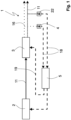
- FIG. 1 illustrates in a block diagram the basic idea of a radiation source 1 according to the invention.
- the radiation source 1 comprises an initial source 2, a frequency converter 3, a conversion detector 4 or 22 and a controller 5.
- the initial source 2 generates an initial electromagnetic radiation 11 with an initial center frequency.
- the frequency converter comprises a converter resonator that resonates with the initial radiation 11 and has a coupling mirror that is partially transparent to the initial radiation 11 and a non-linear optical crystal arranged in the converter resonator.
- the initial radiation 11 is used to pump the non-linear optical frequency converter 3.
- the initial radiation 11 is coupled into the converter resonator by the coupling mirror.
- the frequency converter 3 generates converted radiation 16 with a converted frequency from the initial radiation 11, wherein the converted frequency is different from a frequency of the initial radiation 11.
- the converter resonator of the frequency converter 3 comprises an actuator which can be tuned to tune the resonance frequency of the converter resonator depending on a conversion control signal 19.
- a conversion detector 4 or 22 serves to detect a measure of the power of the converted radiation 16 and to output a conversion measurement signal 18, which represents the measure of the power of the converted radiation 16, to a controller 5.
- a measure of the power of the converted radiation 16 can be determined either by measuring the power of the converted radiation 16 or by measuring the power of the radiation not in the frequency converter 3. converted initial radiation 11. Both variants are in Figure 1 shown schematically.
- the conversion detector 4 is arranged in a beam path of the converted radiation 16.
- the conversion detector 22 is arranged in a beam path of the non-converted initial radiation behind the frequency converter 3.
- the controller 5 is connected to the conversion detector 4, 22 as well as to the actuator, so that the actuator receives the conversion control signal 19 from the controller 5.
- the controller In a first operating mode, the controller generates the conversion control signal 19 depending on the conversion measurement signal 18 such that the resonance frequency is regulated so that it follows the initial center frequency.
- the controller 5 can be selected to switch between the first operating mode and a second operating mode.
- the controller 5 In the second operating mode, the controller 5 generates the conversion control signal 19 such that the power of the converted radiation 16 is regulated such that either the power of the converted radiation 16 has a smaller relative temporal fluctuation than the power of the initial radiation 11 in the beam direction in front of the frequency converter or in front of its coupling mirror, or the power of the initial radiation 11 in the beam direction after the coupling mirror 12 has a smaller relative temporal fluctuation than the power of the initial radiation 11 in the beam direction in front of the coupling mirror.
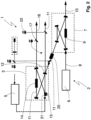
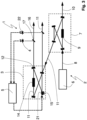
- the Figures 2 and 3 show a concrete realization of a radiation source 1 according to the block diagram of Figure 1 .
- the radiation source 1 from Figures 2 and 3 As before, it comprises an initial source 2, a frequency converter 3, a conversion detector 4 and a controller 5.
- the initial source 2 consists of a pump laser 6 and an optical parametric oscillator (OPO) 7.
- the pump laser 6 generates pump radiation 8 with a pump center frequency.
- the pump radiation 8 is coupled into the OPO and generates idler radiation 10 and signal radiation 11 in a nonlinear optical crystal 9.
- the signal radiation 11 is used to pump a frequency converter in the form of a frequency doubler 3.
- the frequency doubler 3 comprises a doubler resonator designed as a ring resonator 13 with four mirrors.
- a non-linear optical doubler crystal 14 is arranged in the ring resonator 13.
- the doubler resonator 13 is resonant for the signal radiation 11, so that the non-linear optical process of frequency doubling in the doubler crystal 14 is exaggerated.
- a further mirror 21 is mounted on a piezo adjuster 15 as an actuator in the sense of the present application.
- the length of the resonator 13 and thus the resonance frequency can be adjusted and regulated with the help of the controller 5.
- converted radiation 16 is generated from the signal radiation 11, which is doubled in frequency compared to the signal radiation 11.
- a beam splitter 17 is arranged in the beam path of the frequency-doubled radiation 16, via which a part of the frequency-doubled radiation 16 is coupled out and directed to the conversion detector 4.
- the conversion detector 4 in the beam path of the frequency-doubled radiation 16 records a measure of the power of the frequency-doubled radiation 16.
- the controller 5 is now connected to the conversion detector 4 in such a way that the controller 5 receives a conversion measurement signal, which represents the measure of the power of the frequency-doubled radiation 16, from the conversion detector 4 when the radiation source 1 is operating.
- the controller 5 is connected to the piezoelectric adjuster 15 in such a way that the controller 5 receives a conversion control signal 19 from the controller 5 when the radiation source 1 is operating.
- the controller 5 allows a user to select properties of the frequency-doubled radiation 16 with respect to its absolute power and the relative temporal fluctuations of the power.
- the controller 5 is programmed in the embodiment shown in such a way that a user can select between a first and a second operating mode via a user interface and can switch the control of the resonator length of the doubler resonator 13 between these operating modes.
- the first operating mode is in Figure 2 shown schematically and the second operating mode in Figure 3 .
- the resonance frequency is controlled using a Pound-Drever-Hall method.
- an electro-optical modulator 20 is provided in the radiation source 1 in the beam path of the signal radiation 11 between the OPO 7 and the coupling mirror 12 of the frequency doubler 3.
- the modulator 20 is in turn connected to the controller 5 in such a way that the controller 5 specifies a modulation frequency for the modulator 20, with which the modulator 20 imposes a phase modulation on the signal radiation 11.
- the controller 5 also uses the modulation frequency as a reference frequency when controlling the resonator length.
- the aim of controlling the resonator length in the first operating mode is to provide the maximum available power of the converted radiation 16 at any time, while accepting a larger relative temporal fluctuation of the power of the frequency-doubled radiation 16.
- the relative temporal fluctuation of the power of the frequency-doubled radiation 16 is compared with the relative temporal fluctuation of the signal radiation 11 in front of the coupling mirror 12, for example where the reference line of the reference symbol 11 in Figure 2 points to the signal radiation 11.
- the controller mixes the conversion measurement signal 18 with the reference signal to form a mixed signal with a non-modulated (DC) term and a term modulated with twice the modulation frequency.
- the DC term can be easily filtered out of this mixed signal. This is used as an error signal for controlling the resonator length.
- the conversion control signal 19 is generated in such a way that the error signal is minimal.
- the resonator length now follows every change in the center frequency of the signal radiation 11 and the power of the frequency-doubled radiation 16 is essentially always equal to the maximum possible output power of the frequency doubler 3, but is subject to comparatively large relative temporal fluctuations.
- the modulator 20 When switching to the second operating mode, the modulator 20 is switched off by the controller 5 via the modulator control signal 21, since the control in the second operating mode does not require phase modulation of the signal radiation 11.
- This second operating mode is shown schematically in Figure 3 shown in Figure 3 the modulator 20 is not shown.
- the aim of the second operating mode is to provide the frequency-doubled radiation 16 with reduced relative power fluctuation. However, this is done with lower absolute power.
- the controller 5 carries out what is known as side-of-fringe locking in the second operating mode. To do this, the controller 5 forms an error signal as the difference between the conversion measurement signal 18 and a predetermined, constant offset signal.
- the conversion control signal 19 is generated in such a way that the error signal is minimal.
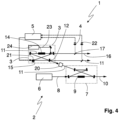
- Figure 4 shows an alternative embodiment of the radiation source 1.
- the radiation source 1 from Figure 4 differs from the radiation source from the Figures 2 and 3 in that the frequency converter 3 is formed by a sum or difference frequency generator instead of a frequency doubler.
- the crystal 14 is selected so that in the crystal converted radiation is generated from the signal radiation 11 and the mixed radiation 23 of a mixed laser 24 with the sum or difference frequency of the frequencies of the signal radiation 11 and the mixed radiation 23.
- the arrangement of Figure 4 can be used as before for the arrangement of Figures 2 and 3 described to switch between the first and second operating modes.
Landscapes
- Physics & Mathematics (AREA)
- Nonlinear Science (AREA)
- Optics & Photonics (AREA)
- General Physics & Mathematics (AREA)
- Electromagnetism (AREA)
- Condensed Matter Physics & Semiconductors (AREA)
- Engineering & Computer Science (AREA)
- Plasma & Fusion (AREA)
- Chemical & Material Sciences (AREA)
- Crystallography & Structural Chemistry (AREA)
- Automation & Control Theory (AREA)
- Lasers (AREA)
Priority Applications (2)
| Application Number | Priority Date | Filing Date | Title |
|---|---|---|---|
| EP22201560.4A EP4354217A1 (fr) | 2022-10-14 | 2022-10-14 | Source de rayonnement et procédé de production d'un rayonnement électromagnétique à plusieurs fréquences |
| US18/379,348 US20240128708A1 (en) | 2022-10-14 | 2023-10-12 | Radiation source and a method for generating electromagnetic radiation at a plurality of frequencies |
Applications Claiming Priority (1)
| Application Number | Priority Date | Filing Date | Title |
|---|---|---|---|
| EP22201560.4A EP4354217A1 (fr) | 2022-10-14 | 2022-10-14 | Source de rayonnement et procédé de production d'un rayonnement électromagnétique à plusieurs fréquences |
Publications (1)
| Publication Number | Publication Date |
|---|---|
| EP4354217A1 true EP4354217A1 (fr) | 2024-04-17 |
Family
ID=83903243
Family Applications (1)
| Application Number | Title | Priority Date | Filing Date |
|---|---|---|---|
| EP22201560.4A Pending EP4354217A1 (fr) | 2022-10-14 | 2022-10-14 | Source de rayonnement et procédé de production d'un rayonnement électromagnétique à plusieurs fréquences |
Country Status (2)
| Country | Link |
|---|---|
| US (1) | US20240128708A1 (fr) |
| EP (1) | EP4354217A1 (fr) |
Citations (1)
| Publication number | Priority date | Publication date | Assignee | Title |
|---|---|---|---|---|
| WO2013106456A1 (fr) * | 2012-01-09 | 2013-07-18 | Ipg Photonics Corporation | Système laser monomode, monofréquence à génération d'harmoniques |
-
2022
- 2022-10-14 EP EP22201560.4A patent/EP4354217A1/fr active Pending
-
2023
- 2023-10-12 US US18/379,348 patent/US20240128708A1/en active Pending
Patent Citations (1)
| Publication number | Priority date | Publication date | Assignee | Title |
|---|---|---|---|---|
| WO2013106456A1 (fr) * | 2012-01-09 | 2013-07-18 | Ipg Photonics Corporation | Système laser monomode, monofréquence à génération d'harmoniques |
Non-Patent Citations (2)
| Title |
|---|
| ERIC D. BLACK: "An introduction to Pound-Drever-Hall laser frequency stabilization", AM. J. PHYS., vol. 69, no. 1, January 2001 (2001-01-01), pages 79 - 87, XP055144240, DOI: 10.1119/1.1286663 |
| T.W. HÄNSCHB. COUILLAUD: "Laser frequency stabilization by polarization spectrocopy of a reflecting reference cavity", OPTICS COMMUNICATIONS, vol. 35, no. 3, December 1980 (1980-12-01), pages 441 - 444 |
Also Published As
| Publication number | Publication date |
|---|---|
| US20240128708A1 (en) | 2024-04-18 |
Similar Documents
| Publication | Publication Date | Title |
|---|---|---|
| DE102008059902B3 (de) | Verfahren und Vorrichtung zum Erzeugen eines selbstrefernzierten optischen Frequenzkamms | |
| EP1161782B1 (fr) | Systeme de production d'impulsions lumineuses ultracourtes stabilisees et son utilisation pour faire la synthese de frequences optiques | |
| EP3227751B1 (fr) | Dispositif et procédé de génération de rayonnement électromagnétique | |
| DE69620126T2 (de) | Verfahren zur Wellenlängenselektion in einem abstimmbaren Laser und Laseroszillator mit wählbarer Wellenlänge in einem abstimmbaren Laser | |
| EP0904561B1 (fr) | Procede et dispositif pour produire au moins trois faisceaux lumineux de differentes longueurs d'ondes, notamment pour une representation couleur | |
| EP2537216B1 (fr) | Système et procédé d'amplification de laser pour générer des impulsions lasers reproductibles | |
| EP2577820A1 (fr) | Procédé de production de champs lumineux à phase cohérente à valeur prédéfinie de leurs fréquences, et synthétiseur de fréquence optique | |
| DE112021000091T5 (de) | Verfahren und vorrichtung zum erzeugen eines optischen frequenzkamms | |
| EP2217966B1 (fr) | Convertisseur de fréquence optique non linéaire, et ses utilisations | |
| DE69321539T2 (de) | Optischer Wellenlängenkonverter | |
| EP3262727A1 (fr) | Peignes de fréquences optique stabilisés | |
| DE102013209848B3 (de) | Verfahren zum Erzeugen eines optischen Pulszugs mit stabilisierter Phase zwischen Träger und Einhüllender mittels spektraler Verschiebung durch einen akustischen Frequenzkamm | |
| DE19634161C2 (de) | Verfahren zum Einstellen und Quelle schmalbandiger kohärenter Strahlung | |
| EP3064992A1 (fr) | Système et procédé optiques | |
| DE60124343T2 (de) | Optischer Frequenzwandler mit reziproker Modulation | |
| WO2004066460A1 (fr) | Resonateur laser et laser a frequence convertie | |
| DE10046898A1 (de) | Verfahren zum Regeln des Arbeitspunktes eines Modulators und zugehörige Ansteuereinheit | |
| DE102005015497B4 (de) | Stabilisierung kaskadierter optischer Resonatoren | |
| DE10339210B4 (de) | Laserresonator und Frequenzkonvertierter Laser | |
| EP0517266A2 (fr) | Laser | |
| DE102007032253B4 (de) | Verfahren zur Variation der Lichtleistung eines mittels einer nichtlinear optischen Anordnung gewonnenen, Frequenz-konvertierten Laserstrahls | |
| DE10252591B4 (de) | Verfahren zur Abbildung eines Videobildes mit mindestens drei Laserstrahlen | |
| DE20011396U1 (de) | Monolithisch integrierte nicht-lineare optische Quasiphasenanpassungsmaterialien zur seriellen und parallelen Lasererzeugung | |
| DE102004046303A1 (de) | Vorrichtung zur Erzeugung von grünem kohärentem Licht unter Verwendung von gleichen nichtlinearen Kristallen | |
| WO2005076420A1 (fr) | Resonateurs optiques couples |
Legal Events
| Date | Code | Title | Description |
|---|---|---|---|
| PUAI | Public reference made under article 153(3) epc to a published international application that has entered the european phase |
Free format text: ORIGINAL CODE: 0009012 |
|
| STAA | Information on the status of an ep patent application or granted ep patent |
Free format text: STATUS: THE APPLICATION HAS BEEN PUBLISHED |
|
| AK | Designated contracting states |
Kind code of ref document: A1 Designated state(s): AL AT BE BG CH CY CZ DE DK EE ES FI FR GB GR HR HU IE IS IT LI LT LU LV MC ME MK MT NL NO PL PT RO RS SE SI SK SM TR |
|
| STAA | Information on the status of an ep patent application or granted ep patent |
Free format text: STATUS: REQUEST FOR EXAMINATION WAS MADE |
|
| 17P | Request for examination filed |
Effective date: 20240715 |
|
| RBV | Designated contracting states (corrected) |
Designated state(s): AL AT BE BG CH CY CZ DE DK EE ES FI FR GB GR HR HU IE IS IT LI LT LU LV MC ME MK MT NL NO PL PT RO RS SE SI SK SM TR |