EP4354247B1 - Wegplanungsverfahren für einen wandkletterroboter - Google Patents
Wegplanungsverfahren für einen wandkletterroboter Download PDFInfo
- Publication number
- EP4354247B1 EP4354247B1 EP22918129.2A EP22918129A EP4354247B1 EP 4354247 B1 EP4354247 B1 EP 4354247B1 EP 22918129 A EP22918129 A EP 22918129A EP 4354247 B1 EP4354247 B1 EP 4354247B1
- Authority
- EP
- European Patent Office
- Prior art keywords
- wall
- climbing robot
- robot
- distance
- lane changing
- Prior art date
- Legal status (The legal status is an assumption and is not a legal conclusion. Google has not performed a legal analysis and makes no representation as to the accuracy of the status listed.)
- Active
Links
Images


Classifications
-
- G—PHYSICS
- G05—CONTROLLING; REGULATING
- G05D—SYSTEMS FOR CONTROLLING OR REGULATING NON-ELECTRIC VARIABLES
- G05D1/00—Control of position, course, altitude or attitude of land, water, air or space vehicles, e.g. using automatic pilots
- G05D1/02—Control of position or course in two dimensions
- G05D1/021—Control of position or course in two dimensions specially adapted to land vehicles
- G05D1/0212—Control of position or course in two dimensions specially adapted to land vehicles with means for defining a desired trajectory
- G05D1/0214—Control of position or course in two dimensions specially adapted to land vehicles with means for defining a desired trajectory in accordance with safety or protection criteria, e.g. avoiding hazardous areas
-
- G—PHYSICS
- G05—CONTROLLING; REGULATING
- G05D—SYSTEMS FOR CONTROLLING OR REGULATING NON-ELECTRIC VARIABLES
- G05D1/00—Control of position, course, altitude or attitude of land, water, air or space vehicles, e.g. using automatic pilots
- G05D1/60—Intended control result
- G05D1/648—Performing a task within a working area or space, e.g. cleaning
-
- G—PHYSICS
- G05—CONTROLLING; REGULATING
- G05D—SYSTEMS FOR CONTROLLING OR REGULATING NON-ELECTRIC VARIABLES
- G05D1/00—Control of position, course, altitude or attitude of land, water, air or space vehicles, e.g. using automatic pilots
- G05D1/20—Control system inputs
- G05D1/24—Arrangements for determining position or orientation
- G05D1/245—Arrangements for determining position or orientation using dead reckoning
-
- G—PHYSICS
- G05—CONTROLLING; REGULATING
- G05D—SYSTEMS FOR CONTROLLING OR REGULATING NON-ELECTRIC VARIABLES
- G05D1/00—Control of position, course, altitude or attitude of land, water, air or space vehicles, e.g. using automatic pilots
- G05D1/60—Intended control result
- G05D1/656—Interaction with payloads or external entities
- G05D1/678—Interaction with payloads or external entities for tethered vehicles
-
- G—PHYSICS
- G05—CONTROLLING; REGULATING
- G05D—SYSTEMS FOR CONTROLLING OR REGULATING NON-ELECTRIC VARIABLES
- G05D2105/00—Specific applications of the controlled vehicles
- G05D2105/10—Specific applications of the controlled vehicles for cleaning, vacuuming or polishing
-
- G—PHYSICS
- G05—CONTROLLING; REGULATING
- G05D—SYSTEMS FOR CONTROLLING OR REGULATING NON-ELECTRIC VARIABLES
- G05D2107/00—Specific environments of the controlled vehicles
- G05D2107/95—Interior or surroundings of another vehicle
-
- G—PHYSICS
- G05—CONTROLLING; REGULATING
- G05D—SYSTEMS FOR CONTROLLING OR REGULATING NON-ELECTRIC VARIABLES
- G05D2109/00—Types of controlled vehicles
- G05D2109/10—Land vehicles
- G05D2109/15—Climbing vehicles
-
- G—PHYSICS
- G05—CONTROLLING; REGULATING
- G05D—SYSTEMS FOR CONTROLLING OR REGULATING NON-ELECTRIC VARIABLES
- G05D2111/00—Details of signals used for control of position, course, altitude or attitude of land, water, air or space vehicles
- G05D2111/50—Internal signals, i.e. from sensors located in the vehicle, e.g. from compasses or angular sensors
- G05D2111/52—Internal signals, i.e. from sensors located in the vehicle, e.g. from compasses or angular sensors generated by inertial navigation means, e.g. gyroscopes or accelerometers
-
- G—PHYSICS
- G05—CONTROLLING; REGULATING
- G05D—SYSTEMS FOR CONTROLLING OR REGULATING NON-ELECTRIC VARIABLES
- G05D2111/00—Details of signals used for control of position, course, altitude or attitude of land, water, air or space vehicles
- G05D2111/50—Internal signals, i.e. from sensors located in the vehicle, e.g. from compasses or angular sensors
- G05D2111/54—Internal signals, i.e. from sensors located in the vehicle, e.g. from compasses or angular sensors for measuring the travel distances, e.g. by counting the revolutions of wheels
Definitions
- the present application relates to the technical field of wall-climbing robots, and in particular to a path planning method for a wall-climbing robot.
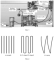
- FIG. 1 is a schematic diagram illustrating a working principle of a robot system.
- a main operation mode of a ship derusting robot is to be safely and reliably adsorbed to a surface of a ship for a derusting operation with a high-pressure water jet module carried.
- this technology is integrated with wall climbing, derusting and recycling, the ship derusting robot needs to carry a high-pressure water pipe, a vacuum recycling pipe and a cable to operate.
- FIG. 2 is a schematic diagram illustrating several types of movement path planning for a wall-climbing robot.
- path planning for the wall-climbing robot mainly includes: straight, N-shaped (Z-shaped) and zigzag path planning.
- a straight crawling trajectory is low in efficiency, the robot can only travel in a straight direction, but cannot crawl back and forth, and for the wall-climbing derusting robot to derust, it will lead to poor consistency at a connection part of a derusting portion and affect the overall derusting quality.
- the robot undergoes a serious tail falling phenomenon, that is, after the robot travels for a period of time, the whole robot will shift downwards for a certain distance, resulting that the robot is unable to operate according to a previously planned path.
- the wall-climbing robot When the wall-climbing robot operates vertically along the wall surface of the ship, with the increase of a climbing height of the robot, the pipe to be dragged correspondingly becomes longer, the gravity of the pipe will increase, and the mass of the load of the robot and a position of its center of gravity will change, resulting in a certain angle deviation of the robot. With the increase of the distance, the deviation value will gradually increase, and manual adjustment is required.
- the lane changing action tests the experience of operators, and the lane changing distance cannot ensure consistency. If the lane changing distance is too small, an overlapping area is caused to be too large and the efficiency is low; and if the lane changing distance is too large, repair missing regions are caused and need to be repaired, and the operation efficiency is reduced.
- the US20100030378 A1 patent document discloses a multi-functional wall climbing robot designed to navigate and perform tasks on vertical and ceiling surfaces of an indoor space.
- the robot employs an IGPS, which consists of navigation transmitters emitting rotating fan beams and a navigation receiver that recognizes these beams as IGPS signals.
- a mobile controller installed on the robot's frame processes these signals to determine the robot's position and control its movement via a drive mechanism.
- the US20130024067A1 patent document discloses a ground vehicle capable of holonomic motion, which allows it to move in any direction while carrying tools such as sensors for non-destructive inspection.
- the vehicle features a frame with four or more Mecanum wheels, each driven by an independently controlled motor, and a plurality of suction devices to maintain precise control on non-level surfaces.
- the CN204772513U patent document discloses a multi-functional robot specifically engineered for performing various tasks on the facades of boats and ships.
- the robot employs magnetic materials to adhere to the vessel's surfaces and features a crawler-type structure for adaptable contact. It is equipped with a stable servo motor system to ensure smooth movement and a rotating operating platform that can accommodate a range of working tools, such as spray guns, welding guns, and cutters.
- the related art only considers the operation in a vertical mode and never considers the operation in a horizontal mode.
- the wall-climbing robot performs horizontal operation along the wall surface of the ship, the robot will undergo the tail falling phenomenon due to the influence of the gravity of the robot itself and the load, and the above problems will be more serious.
- the present application provides a path planning method for a wall-climbing robot.
- the present disclosure mainly solves the problems of path planning, vertical face straight walking and automatic lane changing of the robot, and the robot implements automated operation according to the path planning, vertical face straight walking and automatic lane changing, so that people are freed from frequently operating a remote controller and performing real-time monitoring, and the robot is more intelligent.
- the functions of vertical face straight walking and automatic lane changing of the wall-climbing robot are realized, so that a whole robot system is more automatic and the work efficiency is improved.
- a path planning method for a wall-climbing robot includes following steps:
- the analyzing the crawling capability of the wall-climbing robot in step 3 specifically includes: dividing crawling movement modes of the wall-climbing robot on a wall surface of a ship into a vertical mode and a horizontal mode.
- the vertical mode includes vertical upward movement and vertical downward movement
- the wall-climbing robot in the vertical upward movement needs to overcome a resistance moment caused by the gravity of a body and the gravity of the load of the robot and a resistance moment caused by friction of wheel sets, and when a speed is constant, a resistance moment of the wall-climbing robot in the vertical upward movement is greater than a resistance moment in the downward movement.
- the vertical mode is implemented by following steps:
- the horizontal mode includes horizontal forward movement and horizontal backward movement, and in horizontal movement of the wall-climbing robot, the wall-climbing robot needs to overcome the resistance moment caused by the gravity of the body and the gravity of the load of the wall-climbing robot and the resistance moment caused by the friction of the wheel sets.
- the analyzing the steering capability of the wall-climbing robot in step 3 specifically includes:
- implementation of lane changing by the wall-climbing robot specifically includes:
- the following technical effects can be obtained: compared with the existing path planning, according to the present disclosure, the advantages of Z-shaped (N-shaped) and zigzag path planning are integrated, operation steps for lane changing are reduced, an overlapping region is reduced and the operation efficiency is improved. Above all, the automated operation is realized, and does not rely on the experience of the operator. The tail falling phenomenon is avoided by rotating a certain compensation angle, so that the robot can walk in a horizontal line instead of a previous curve in the horizontal mode, and inside path navigation and automatic lane changing can be better realized.
- the solution of the present disclosure is used for solving the problems above, and by means of the solution, the robot implements automated operation according to path planning, straight walking and automated lane changing, the operator is freed from frequently operating the remote controller and performing real-time monitoring, and the robot is more intelligent.
- a path planning method of the present disclosure includes the following steps.
- Step 1 establishing a spatial pose model of a wall-climbing robot during a working process.
- FIG. 3 is a schematic diagram illustrating a spatial pose model of a wall-climbing robot during a working process, where an OXYZ coordinate system is a ground coordinate system and an OXYZ coordinate system is a ship wall surface coordinate system.
- ⁇ is an included angle between a wall surface of a ship and a vertical plane. According to an actual situation of the wall surface, it can be known that 0 ⁇ 90.
- Step 3 performing kinetics analysis on the wall-climbing robot, and analyzing a crawling capability and a steering capability of the wall-climbing robot.
- Crawling movement modes of the wall-climbing robot on the wall surface of the ship is divided into a vertical mode and a horizontal mode.
- the wall-climbing robot in the vertical upward movement needs to overcome resistance moments in identical directions, that is, a resistance moment caused by the gravity of a body of the robot and the gravity of a load, and a resistance moment caused by friction of the wheel sets; and when the speed is constant, a resistance moment of the wall-climbing robot in the vertical upward movement is greater than a resistance moment in the downward movement.
- FIG. 4 is a schematic diagram illustrating stress analysis, where G Z represents a component of a sum of the gravity of the body of the wall-climbing robot and the gravity of the load borne by the wall-climbing robot along a z axis in the OXYZ coordinate system, M represents a friction force of the wheel sets when the wall-climbing robot moves upwards, M' represents a friction force of the wheel sets when the wall-climbing robot moves downwards, F represents a driving force when the wall-climbing robot moves upwards, and F' represents a driving force when the wall-climbing robot moves downwards.
- G Z represents a component of a sum of the gravity of the body of the wall-climbing robot and the gravity of the load borne by the wall-climbing robot along a z axis in the OXYZ coordinate system
- M represents a friction force of the wheel sets when the wall-climbing robot moves upwards
- M' represents a friction force of the wheel sets when the wall-climb
- the wall-climbing robot in the vertical mode, can walk straight only by keeping a crawling angle unchanged.
- the wall-climbing robot is equipped with an inertial measurement unit (IMU) module.
- IMU inertial measurement unit
- the horizontal mode includes horizontal forward movement and horizontal backward movement, and in horizontal movement of the wall-climbing robot, the wall-climbing robot needs to overcome resistance moments in two directions, that is, the resistance moment caused by the gravity of the body of the wall-climbing robot and the gravity of the load, and the resistance moment caused by the friction of the wheel sets.
- G Z represents the component of the sum of the gravity of the body of the wall-climbing robot and the gravity of the load borne by the wall-climbing robot along the z axis in the OXYZ coordinate system
- M represents a friction force of the wheel sets when the wall-climbing robot moves forward
- M' represents a friction force of the wheel sets when the wall-climbing robot moves backward
- F represents a driving force when the wall-climbing robot moves forward
- F' represents a driving force when the wall-climbing robot moves backward.
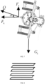
- FIG. 7 is a schematic diagram illustrating stress analysis of automated operation of a robot after compensation, where Q represents a resultant force of a driving force and a friction force when the robot moves forward, F Z represents a component of the resultant force in the z axis direction, F X represents a component of the resultant force in an x axis direction, and ⁇ is a set offset angle.
- the horizontal mode is technically implemented by the following steps:
- the wall-climbing robot is involved in steering movement during a working process, the action is realized by differential motion of driving wheels of the wall-climbing robot, and sideslip occurs when a driving wheel on one side rotate fast and a driving wheel on the other side rotates slowly, so as to perform the steering movement.
- a rotation speed and a rotation radius of the wall-climbing robot during a steering process are also codetermined by movement directions and speeds of the driving wheels, and the rotation radius directly determines a lane changing distance of the wall-climbing robot.
- FIG. 9 is a schematic diagram illustrating steering of wheel sets on two sides of a robot.
- a point a, a point b and a point c are centers of the wheel sets on two sides and the body of the robot respectively, with O 1 representing a center of first steering of the robot and O 2 representing a center of second steering of the robot.
- O 1 representing a center of first steering of the robot
- O 2 representing a center of second steering of the robot.
- v c v a + v b 2
- r v a + v b v a ⁇ v b . B 2 ;
- FIG. 10 is a schematic diagram illustrating lane changing of a robot.
- the implementation of lane changing by the wall-climbing robot specifically includes:
- the advantages of Z-shaped (N-shaped) and zigzag path planning are integrated, operation steps for lane changing are reduced, an overlapping region is reduced and the operation efficiency is improved.
- the automated operation is realized, and does not rely on the experience of the operator.
- the tail falling phenomenon is avoided by rotating a certain compensation angle, so that the robot can walk in a horizontal line instead of a previous curve in the horizontal mode, and inside path navigation and automatic lane changing can be better realized.
Landscapes
- Engineering & Computer Science (AREA)
- Aviation & Aerospace Engineering (AREA)
- Radar, Positioning & Navigation (AREA)
- Remote Sensing (AREA)
- Physics & Mathematics (AREA)
- General Physics & Mathematics (AREA)
- Automation & Control Theory (AREA)
- Manipulator (AREA)
- Control Of Position, Course, Altitude, Or Attitude Of Moving Bodies (AREA)
Claims (4)
- Eine Wegplanungsmethode für einen Wandkletterroboter, die Methode umfassend folgende Schritte:Schritt 1, Erstellen eines räumlichen Posemodells eines Wandkletterroboters während eines Arbeitsprozesses;Schritt 2, Durchführen einer statischen Analyse am Wandkletterroboter und Zerlegung einer resultierenden Kraft G der Schwerkraft des Wandkletterroboters selbst und der Schwerkraft einer von dem Wandkletterroboter getragenen Last;Schritt 3, Durchführen einer Kinetikanalyse am Wandkletterroboter und Analysieren einer Kriechfähigkeit und einer Lenkfähigkeit des Wandkletterroboters; undSchritt 4, Durchführen der Wegplanung gemäß den Analyseergebnissen der Kriechfähigkeit und der Lenkfähigkeit;dadurch gekennzeichnet, dass die Analyse der Lenkfähigkeit des Wandkletterroboters in Schritt 3 insbesondere umfasst:Mitbestimmen einer Drehgeschwindigkeit und eines Drehradius des Wandkletterroboters während eines Lenkvorgangs durch Bewegungsrichtungen und Geschwindigkeiten von Antriebsrädern, wobei der Drehradius direkt einen Spurwechselabstand des Wandkletterroboters bestimmt;wenn die Bewegungsrichtungen zweier Antriebsräder identisch sind, die Geschwindigkeitsrichtungen der Radsätze auf zwei Seiten identisch sind und sich ein Drehpunkt auf einer Außenseite des Wandkletterroboters befindet;wenn sich die Bewegungsrichtungen der beiden Antriebsräder gegenüberliegen, die Geschwindigkeitsrichtungen der Radsätze auf beiden Seiten gegenüberliegen und sich der Drehpunkt auf einer Innenseite des Wandkletterroboters befindet;Wenn die Geschwindigkeitsrichtungen der Radsätze auf beiden Seiten identisch sind, ergibt sich folgende Formel:
 wenn sich die Geschwindigkeitsrichtungen der Radsätze auf beiden Seiten gegenüberliegen, ergibt sich folgende Formel:
 wobei ein Punkt a, ein Punkt b und ein Punkt c Mittelpunkte der Radsätze auf den beiden Seiten und ein Körper des Wandkletterroboters sind, r einen Lenkradius des Wandkletterroboters darstellt, die der Hälfte des Spurwechselabstands entspricht L, Va und Vb Geschwindigkeiten der Radsätze auf beiden Seiten des Wandkletterroboters ist, Vc eine Geschwindigkeit des Körpers des Wandkletterroboters ist und B ein Abstand zwischen dem Punkt a und dem Punkt b ist;wobei die Implementierung eines Spurwechsels durch den Wandkletterroboter insbesondere umfasst:Berechnen des Lenkradius r des Roboters entsprechend dem eingestellten Spurwechselabstand L, um die Geschwindigkeiten Va und Vb der Radsätze auf den beiden Seiten des Wandkletterroboters für das erste Lenken zu berechnen; undStarten des zweiten Lenkens durch den Wandkletterroboter, wenn ein Drehwinkel der ersten Lenkung 90 Grad erreicht, und erneutes Drehen um 90 Grad in eine entgegengesetzte Richtung der ersten Lenkung, um einen Spurwechselvorgang abzuschließen;wobei die Analyse der Kriechfähigkeit des Wandkletterroboters in Schritt 3 insbesondere umfasst: Unterteilen von Kriechbewegungsmodi des Wandkletterroboters auf einer Wandfläche eines Schiffes in einen vertikalen Modus und einen horizontalen Modus;wobei der vertikale Modus durch folgende Schritte umgesetzt wird:Schritt 301, manuelles Anpassen des Wandkletterroboters in eine vertikale Haltung und Aufzeichnen eines aktuellen Rückkopplungswinkels a eines Trägheitsmesseinheitsmoduls; undSchritt 302, Einstellen einer Laufstrecke und der Spurwechselstrecke des Wandkletterroboters und Starten, durch den Wandkletterroboter, des automatisierten Betriebs entsprechend dem aktuellen Rückkopplungswinkel, wobei ein abgeschlossener Betriebsbereich S*L*N ist, wobei S die Laufstrecke und L die eingestellte Spurwechselstrecke darstellt, und N für eine Anzahl von Spurwechseln steht;wobei der horizontale Modus technisch durch folgende Schritte umgesetzt wird:Schritt 301', manuelles Anpassen des Wandkletterroboters in eine horizontale Haltung und das Aufzeichnen eines aktuellen Rückkopplungswinkels α1 des Trägheitsmesseinheitsmoduls;Schritt 302', der es dem Wandkletterroboter ermöglicht, die eingestellte Laufstrecke S vorwärts zu bewegen, und einen aktuellen Rückkopplungswinkel α2 des Trägheitsmesseinheitsmoduls aufzeichnet;Schritt 303', wobei eine Differenz zwischen den beiden Winkeln αf = α2-α1 berechnet wird und αf als ein eingestellter Versatzwinkel für den Wandkletterroboter verwendet wird, der sich um den Abstand S vorwärts bewegt;Schritt 304', manuelles Anpassen des Wandkletterroboters in die dem Rückkopplungswinkel α1 entsprechende horizontale Haltung;Schritt 305', der es dem Wandkletterroboter ermöglicht, sich um den eingestellten Abstand S rückwärts zu bewegen, und einen aktuellen Rückkopplungswinkel α3 des aktuellen Trägheitsmesseinheitsmoduls aufzeichnet;Schritt 306', das Berechnen einer Differenz zwischen den beiden Winkeln αb = α3-α1 und das Annehmen von αb als ein eingestellter Versatzwinkel für den Wandkletterroboter, der sich um den Abstand S rückwärts bewegt; undSchritt 307', Durchführen eines automatisierten Betriebs durch den Wandkletterroboter, entsprechend den zweimal gemessenen Versatzwinkeln αf und αb. wobei ein Betriebsbereich S*L*N ist, wobei S die Laufstrecke des Roboters, L die eingestellte Spurwechselstrecke und N die Anzahl der Spurwechsel darstellt.
 - Verfahren nach Anspruch 1, wobei der vertikale Modus eine vertikale Aufwärtsbewegung und eine vertikale Abwärtsbewegung umfasst; der Wandkletterroboter muss in der vertikalen Aufwärtsbewegung ein Widerstandsmoment überwinden, das durch die Schwerkraft des Körpers und die Schwerkraft der Last des Roboters und ein Widerstandsmoment, das durch Reibung der Radsätze verursacht wird, verursacht wird; und bei konstanter Geschwindigkeit ist ein Widerstandsmoment des Wandkletterroboters in der vertikalen Aufwärtsbewegung größer als ein Widerstandsmoment in der Abwärtsbewegung.
- Verfahren nach Anspruch 1, wobei der horizontale Modus eine horizontale Vorwärtsbewegung und eine horizontale Rückwärtsbewegung umfasst; und in der horizontalen Bewegung des Wandkletterroboters muss der Wandkletterroboter ein Widerstandsmoment überwinden, das durch die Schwerkraft des Körpers und die Schwerkraft der Last des Wandkletterroboters und ein Widerstandsmoment durch Reibung der Radsätze verursacht wird.
- Verfahren nach Anspruch 1, wobei im horizontalen Modus aufgrund eines Einflusses der Schwerkraft Gz eine Aufwärtskraft Fz zur Kompensation erforderlich ist; undim horizontalen Modus lautet die Gleichung für das Kräftegleichgewicht des an der Wand kletternden Roboters wie folgt:
 wobei Q eine resultierende Kraft einer Antriebskraft und eine Reibekraft beim Vorwärtsbewegen des Roboters darstellt, Fz eine Komponente der resultierenden Kraft in z-Richtung, Fx eine Komponente der resultierenden Kraft in x-Richtung, α ein eingestellter Versatzwinkel, M eine Reibekraft des Radsatzes beim Vorwärtsbewegen des Wandkletterroboters und F eine Antriebskraft beim Vorwärtsbewegen des Wandkletterroboters darstellt.
Applications Claiming Priority (2)
| Application Number | Priority Date | Filing Date | Title |
|---|---|---|---|
| CN202210000699.6A CN114019986B (zh) | 2022-01-04 | 2022-01-04 | 一种爬壁机器人的路径规划方法 |
| PCT/CN2022/098581 WO2023130673A1 (zh) | 2022-01-04 | 2022-06-14 | 一种爬壁机器人的路径规划方法 |
Publications (4)
| Publication Number | Publication Date |
|---|---|
| EP4354247A1 EP4354247A1 (de) | 2024-04-17 |
| EP4354247A4 EP4354247A4 (de) | 2024-09-18 |
| EP4354247C0 EP4354247C0 (de) | 2025-04-23 |
| EP4354247B1 true EP4354247B1 (de) | 2025-04-23 |
Family
ID=80069432
Family Applications (1)
| Application Number | Title | Priority Date | Filing Date |
|---|---|---|---|
| EP22918129.2A Active EP4354247B1 (de) | 2022-01-04 | 2022-06-14 | Wegplanungsverfahren für einen wandkletterroboter |
Country Status (3)
| Country | Link |
|---|---|
| EP (1) | EP4354247B1 (de) |
| CN (1) | CN114019986B (de) |
| WO (1) | WO2023130673A1 (de) |
Families Citing this family (8)
| Publication number | Priority date | Publication date | Assignee | Title |
|---|---|---|---|---|
| CN114019986B (zh) * | 2022-01-04 | 2022-05-20 | 北京史河科技有限公司 | 一种爬壁机器人的路径规划方法 |
| CN114578820B (zh) * | 2022-03-02 | 2024-05-07 | 上海核工程研究设计院股份有限公司 | 一种核电站检测爬壁机器人的行进轨迹控制方法 |
| CN115793433B (zh) * | 2023-01-06 | 2023-05-05 | 北京史河科技有限公司 | 一种机器人下滑纠偏控制方法和下滑纠偏底盘、机器人 |
| CN116752816B (zh) * | 2023-06-15 | 2026-01-06 | 星迈创新科技(苏州)有限公司 | 一种水池机器人的控制方法、存储介质 |
| CN117434938B (zh) * | 2023-07-31 | 2025-02-18 | 南通中远海运船务工程有限公司 | 一种船舶清洗智能控制系统及其控制方法 |
| CN117001664A (zh) * | 2023-08-09 | 2023-11-07 | 河北工业大学 | 一种立面移动机械臂系统防倾覆检测及控制方法 |
| CN119002477B (zh) * | 2024-07-31 | 2025-05-27 | 哈尔滨工业大学 | 一种基于可变形轮的爬楼机器人的智能爬楼方法 |
| CN120066054B (zh) * | 2025-04-25 | 2025-07-18 | 深圳逐际动力科技有限公司 | 基于深度强化学习的双轮足机器人通过高度障碍控制方法及装置、运动控制模型训练方法 |
Family Cites Families (21)
| Publication number | Priority date | Publication date | Assignee | Title |
|---|---|---|---|---|
| KR100812724B1 (ko) * | 2006-09-29 | 2008-03-12 | 삼성중공업 주식회사 | 실내 위치측정시스템을 이용한 벽면 이동 로봇 |
| US8738226B2 (en) * | 2011-07-18 | 2014-05-27 | The Boeing Company | Holonomic motion vehicle for travel on non-level surfaces |
| CN203019367U (zh) * | 2012-12-13 | 2013-06-26 | 浙江大学 | 一种具有曲面自适应吸附的磁轮式爬壁机器人 |
| CN204772513U (zh) * | 2015-05-18 | 2015-11-18 | 浙江理工大学 | 一种船舶立面作业多功能爬行机器人 |
| KR101815394B1 (ko) * | 2015-10-27 | 2018-01-05 | 한국과학기술원 | 벽면 이동을 위한 비행로봇 메커니즘 및 제어방법 |
| CN106437581B (zh) * | 2015-11-14 | 2019-08-23 | 西安旭丰科技发展有限责任公司 | 一种液压驱动模式的大牵引力爬行器 |
| CN105365912B (zh) * | 2015-12-18 | 2017-10-20 | 哈尔滨科能熔敷科技有限公司 | 一种锅炉水冷壁熔敷层多点同步测厚的爬壁机器人 |
| CN105935272B (zh) * | 2016-06-21 | 2018-11-06 | 深圳市博飞航空科技有限公司 | 一种爬壁装置的爬行控制方法及系统 |
| CN208085842U (zh) * | 2017-07-31 | 2018-11-13 | 广东省智能制造研究所 | 一种履带式爬壁机器人 |
| WO2019128521A1 (zh) * | 2017-12-27 | 2019-07-04 | 杭州高越科技有限公司 | 水下清洗机器人及其爬行方法、运动路径规划方法和系统 |
| CN108413976A (zh) * | 2018-01-23 | 2018-08-17 | 大连理工大学 | 一种面向多工况的爬壁机器人智能路径规划方法及系统 |
| KR102581198B1 (ko) * | 2018-04-16 | 2023-09-22 | 한국전자통신연구원 | 신발 모델을 이용한 보행 항법 장치 및 그 방법 |
| CN108655135A (zh) * | 2018-07-02 | 2018-10-16 | 洛阳圣瑞智能机器人有限公司 | 船舶、石化储罐壁面爬壁除锈机器人工作系统 |
| US11007635B2 (en) * | 2018-07-25 | 2021-05-18 | The Boeing Company | Gravity compensation for self-propelled robotic vehicles crawling on non-level surfaces |
| CN110667719B (zh) * | 2019-10-16 | 2021-11-30 | 山东交通学院 | 一种船用全向移动爬壁机器人 |
| CN112720451B (zh) * | 2019-10-28 | 2021-12-03 | 深圳市行知行机器人技术有限公司 | 自动作业机器人及其按规划路径自动作业的控制方法 |
| CN110850879A (zh) * | 2019-11-20 | 2020-02-28 | 蒋念恒 | 一种爬壁机器人自动巡航作业方法 |
| CN112045679B (zh) * | 2020-08-21 | 2022-05-10 | 上海核工程研究设计院有限公司 | 一种爬壁机器人防倾覆行进控制方法 |
| CN113467461B (zh) * | 2021-07-13 | 2022-04-01 | 燕山大学 | 移动机器人非结构化环境下的人机协作式路径规划方法 |
| CN113844221B (zh) * | 2021-09-26 | 2024-02-02 | 西北工业大学 | 一种两栖三模态飞行吸附爬壁机器人及控制方法 |
| CN114019986B (zh) * | 2022-01-04 | 2022-05-20 | 北京史河科技有限公司 | 一种爬壁机器人的路径规划方法 |
-
2022
- 2022-01-04 CN CN202210000699.6A patent/CN114019986B/zh active Active
- 2022-06-14 EP EP22918129.2A patent/EP4354247B1/de active Active
- 2022-06-14 WO PCT/CN2022/098581 patent/WO2023130673A1/zh not_active Ceased
Also Published As
| Publication number | Publication date |
|---|---|
| CN114019986B (zh) | 2022-05-20 |
| EP4354247C0 (de) | 2025-04-23 |
| CN114019986A (zh) | 2022-02-08 |
| EP4354247A4 (de) | 2024-09-18 |
| EP4354247A1 (de) | 2024-04-17 |
| WO2023130673A1 (zh) | 2023-07-13 |
Similar Documents
| Publication | Publication Date | Title |
|---|---|---|
| EP4354247B1 (de) | Wegplanungsverfahren für einen wandkletterroboter | |
| EP2734343B1 (de) | Bewegliche Plattform | |
| CN107584501B (zh) | 一种变电站设备带电清洗机器人及其控制方法 | |
| CN113021382B (zh) | 全自动智能喷涂机器人 | |
| CN113459099A (zh) | 一种船体焊缝打磨机器人及其使用方法 | |
| Chen et al. | Omni-directional robot and adaptive control method for off-road running | |
| WO2022252220A1 (zh) | 一种多轴线平板车精准停靠系统及方法 | |
| CN114811265A (zh) | 一种管道探测装置及系统 | |
| CN117988848A (zh) | 深海机械手与水力采集一体化智能悬浮式采矿装备 | |
| CN115562097A (zh) | 一种履带式液压挖掘机上下无爬梯板车的智能控制系统 | |
| CN112379675B (zh) | 环卫机器人的控制方法及系统、环卫机器人 | |
| CN112882475A (zh) | 麦克纳姆轮式全方位移动机器人的运动控制方法及装置 | |
| CN114296454B (zh) | 一种全向全驱移动机器人的自适应运动控制方法及系统 | |
| Akizono et al. | Development on walking robot for underwater inspection | |
| CN117302372B (zh) | 一种多级履带摆臂式无人越障机器人以及越障方法 | |
| CN114610048B (zh) | 基于叉型摇臂轮腿复合越障机构的机器人及自主越障方法 | |
| US12448754B2 (en) | Load based tracking assist | |
| CN109460038A (zh) | 一种惯导重载agv系统及其控制方法 | |
| CN116149173A (zh) | 一种海洋平台导管架清洗机器人及其控制方法 | |
| CN116952944A (zh) | 一种船体焊缝缺陷检测识别装置及方法 | |
| CN117449388B (zh) | 基于激光导引的建筑场地整平作业方法、系统和挖掘机 | |
| CN120742902B (zh) | 磁吸爬壁器的爬壁路径控制方法、系统及应用 | |
| CN221698854U (zh) | 一种自主建图导航的履带式机器人 | |
| JPH0786768B2 (ja) | 無人走行車の走行制御装置 | |
| CN116242363A (zh) | 无人机引导的挖掘机自主作业方法及其系统 |
Legal Events
| Date | Code | Title | Description |
|---|---|---|---|
| STAA | Information on the status of an ep patent application or granted ep patent |
Free format text: STATUS: THE INTERNATIONAL PUBLICATION HAS BEEN MADE |
|
| PUAI | Public reference made under article 153(3) epc to a published international application that has entered the european phase |
Free format text: ORIGINAL CODE: 0009012 |
|
| STAA | Information on the status of an ep patent application or granted ep patent |
Free format text: STATUS: REQUEST FOR EXAMINATION WAS MADE |
|
| 17P | Request for examination filed |
Effective date: 20240112 |
|
| AK | Designated contracting states |
Kind code of ref document: A1 Designated state(s): AL AT BE BG CH CY CZ DE DK EE ES FI FR GB GR HR HU IE IS IT LI LT LU LV MC MK MT NL NO PL PT RO RS SE SI SK SM TR |
|
| REG | Reference to a national code |
Ref legal event code: R079 Free format text: PREVIOUS MAIN CLASS: G05D0001020000 Ref country code: DE Ref legal event code: R079 Ref document number: 602022013720 Country of ref document: DE Free format text: PREVIOUS MAIN CLASS: G05D0001020000 Ipc: G05D0001000000 |
|
| STAA | Information on the status of an ep patent application or granted ep patent |
Free format text: STATUS: EXAMINATION IS IN PROGRESS |
|
| A4 | Supplementary search report drawn up and despatched |
Effective date: 20240816 |
|
| RIC1 | Information provided on ipc code assigned before grant |
Ipc: G05D 1/648 20240101ALI20240809BHEP Ipc: G05D 111/50 20240101ALI20240809BHEP Ipc: G05D 109/15 20240101ALI20240809BHEP Ipc: G05D 107/00 20240101ALI20240809BHEP Ipc: G05D 105/10 20240101ALI20240809BHEP Ipc: G05D 1/678 20240101ALI20240809BHEP Ipc: G05D 1/245 20240101ALI20240809BHEP Ipc: G05D 1/00 20240101AFI20240809BHEP |
|
| 17Q | First examination report despatched |
Effective date: 20240828 |
|
| GRAP | Despatch of communication of intention to grant a patent |
Free format text: ORIGINAL CODE: EPIDOSNIGR1 |
|
| STAA | Information on the status of an ep patent application or granted ep patent |
Free format text: STATUS: GRANT OF PATENT IS INTENDED |
|
| RIC1 | Information provided on ipc code assigned before grant |
Ipc: G05D 1/648 20240101ALI20241128BHEP Ipc: G05D 111/50 20240101ALI20241128BHEP Ipc: G05D 109/15 20240101ALI20241128BHEP Ipc: G05D 107/00 20240101ALI20241128BHEP Ipc: G05D 105/10 20240101ALI20241128BHEP Ipc: G05D 1/678 20240101ALI20241128BHEP Ipc: G05D 1/245 20240101ALI20241128BHEP Ipc: G05D 1/00 20240101AFI20241128BHEP |
|
| DAV | Request for validation of the european patent (deleted) | ||
| DAX | Request for extension of the european patent (deleted) | ||
| INTG | Intention to grant announced |
Effective date: 20241217 |
|
| GRAS | Grant fee paid |
Free format text: ORIGINAL CODE: EPIDOSNIGR3 |
|
| GRAA | (expected) grant |
Free format text: ORIGINAL CODE: 0009210 |
|
| STAA | Information on the status of an ep patent application or granted ep patent |
Free format text: STATUS: THE PATENT HAS BEEN GRANTED |
|
| AK | Designated contracting states |
Kind code of ref document: B1 Designated state(s): AL AT BE BG CH CY CZ DE DK EE ES FI FR GB GR HR HU IE IS IT LI LT LU LV MC MK MT NL NO PL PT RO RS SE SI SK SM TR |
|
| REG | Reference to a national code |
Ref country code: GB Ref legal event code: FG4D |
|
| REG | Reference to a national code |
Ref country code: CH Ref legal event code: EP |
|
| REG | Reference to a national code |
Ref country code: DE Ref legal event code: R096 Ref document number: 602022013720 Country of ref document: DE |
|
| REG | Reference to a national code |
Ref country code: IE Ref legal event code: FG4D |
|
| U01 | Request for unitary effect filed |
Effective date: 20250520 |
|
| U07 | Unitary effect registered |
Designated state(s): AT BE BG DE DK EE FI FR IT LT LU LV MT NL PT RO SE SI Effective date: 20250527 |
|
| U20 | Renewal fee for the european patent with unitary effect paid |
Year of fee payment: 4 Effective date: 20250619 |
|
| PG25 | Lapsed in a contracting state [announced via postgrant information from national office to epo] |
Ref country code: ES Free format text: LAPSE BECAUSE OF FAILURE TO SUBMIT A TRANSLATION OF THE DESCRIPTION OR TO PAY THE FEE WITHIN THE PRESCRIBED TIME-LIMIT Effective date: 20250423 |
|
| PG25 | Lapsed in a contracting state [announced via postgrant information from national office to epo] |
Ref country code: NO Free format text: LAPSE BECAUSE OF FAILURE TO SUBMIT A TRANSLATION OF THE DESCRIPTION OR TO PAY THE FEE WITHIN THE PRESCRIBED TIME-LIMIT Effective date: 20250723 Ref country code: GR Free format text: LAPSE BECAUSE OF FAILURE TO SUBMIT A TRANSLATION OF THE DESCRIPTION OR TO PAY THE FEE WITHIN THE PRESCRIBED TIME-LIMIT Effective date: 20250724 |
|
| PG25 | Lapsed in a contracting state [announced via postgrant information from national office to epo] |
Ref country code: PL Free format text: LAPSE BECAUSE OF FAILURE TO SUBMIT A TRANSLATION OF THE DESCRIPTION OR TO PAY THE FEE WITHIN THE PRESCRIBED TIME-LIMIT Effective date: 20250423 |
|
| PG25 | Lapsed in a contracting state [announced via postgrant information from national office to epo] |
Ref country code: HR Free format text: LAPSE BECAUSE OF FAILURE TO SUBMIT A TRANSLATION OF THE DESCRIPTION OR TO PAY THE FEE WITHIN THE PRESCRIBED TIME-LIMIT Effective date: 20250423 |
|
| PG25 | Lapsed in a contracting state [announced via postgrant information from national office to epo] |
Ref country code: RS Free format text: LAPSE BECAUSE OF FAILURE TO SUBMIT A TRANSLATION OF THE DESCRIPTION OR TO PAY THE FEE WITHIN THE PRESCRIBED TIME-LIMIT Effective date: 20250723 |
|
| PG25 | Lapsed in a contracting state [announced via postgrant information from national office to epo] |
Ref country code: IS Free format text: LAPSE BECAUSE OF FAILURE TO SUBMIT A TRANSLATION OF THE DESCRIPTION OR TO PAY THE FEE WITHIN THE PRESCRIBED TIME-LIMIT Effective date: 20250823 |
|
| U1N | Appointed representative for the unitary patent procedure changed after the registration of the unitary effect |
Representative=s name: SANTARELLI; FR |
|
| PG25 | Lapsed in a contracting state [announced via postgrant information from national office to epo] |
Ref country code: SM Free format text: LAPSE BECAUSE OF FAILURE TO SUBMIT A TRANSLATION OF THE DESCRIPTION OR TO PAY THE FEE WITHIN THE PRESCRIBED TIME-LIMIT Effective date: 20250423 |
|
| PG25 | Lapsed in a contracting state [announced via postgrant information from national office to epo] |
Ref country code: CZ Free format text: LAPSE BECAUSE OF FAILURE TO SUBMIT A TRANSLATION OF THE DESCRIPTION OR TO PAY THE FEE WITHIN THE PRESCRIBED TIME-LIMIT Effective date: 20250423 |
|
| PG25 | Lapsed in a contracting state [announced via postgrant information from national office to epo] |
Ref country code: SK Free format text: LAPSE BECAUSE OF FAILURE TO SUBMIT A TRANSLATION OF THE DESCRIPTION OR TO PAY THE FEE WITHIN THE PRESCRIBED TIME-LIMIT Effective date: 20250423 |
|
| REG | Reference to a national code |
Ref country code: CH Ref legal event code: H13 Free format text: ST27 STATUS EVENT CODE: U-0-0-H10-H13 (AS PROVIDED BY THE NATIONAL OFFICE) Effective date: 20260127 |
|
| PG25 | Lapsed in a contracting state [announced via postgrant information from national office to epo] |
Ref country code: MC Free format text: LAPSE BECAUSE OF FAILURE TO SUBMIT A TRANSLATION OF THE DESCRIPTION OR TO PAY THE FEE WITHIN THE PRESCRIBED TIME-LIMIT Effective date: 20250423 |
|
| PLBE | No opposition filed within time limit |
Free format text: ORIGINAL CODE: 0009261 |
|
| STAA | Information on the status of an ep patent application or granted ep patent |
Free format text: STATUS: NO OPPOSITION FILED WITHIN TIME LIMIT |
|
| REG | Reference to a national code |
Ref country code: CH Ref legal event code: L10 Free format text: ST27 STATUS EVENT CODE: U-0-0-L10-L00 (AS PROVIDED BY THE NATIONAL OFFICE) Effective date: 20260304 |
|
| 26N | No opposition filed |
Effective date: 20260126 |
|
| PG25 | Lapsed in a contracting state [announced via postgrant information from national office to epo] |
Ref country code: IE Free format text: LAPSE BECAUSE OF NON-PAYMENT OF DUE FEES Effective date: 20250614 |
|
| PG25 | Lapsed in a contracting state [announced via postgrant information from national office to epo] |
Ref country code: CH Free format text: LAPSE BECAUSE OF NON-PAYMENT OF DUE FEES Effective date: 20250630 |