EP4354249A1 - Stützanordnung für einen joystick zum steuern eines fahrzeugs - Google Patents
Stützanordnung für einen joystick zum steuern eines fahrzeugs Download PDFInfo
- Publication number
- EP4354249A1 EP4354249A1 EP22200671.0A EP22200671A EP4354249A1 EP 4354249 A1 EP4354249 A1 EP 4354249A1 EP 22200671 A EP22200671 A EP 22200671A EP 4354249 A1 EP4354249 A1 EP 4354249A1
- Authority
- EP
- European Patent Office
- Prior art keywords
- mounting
- ball
- mounting device
- joystick
- elements
- Prior art date
- Legal status (The legal status is an assumption and is not a legal conclusion. Google has not performed a legal analysis and makes no representation as to the accuracy of the status listed.)
- Pending
Links
Images



Classifications
-
- G—PHYSICS
- G05—CONTROLLING; REGULATING
- G05G—CONTROL DEVICES OR SYSTEMS INSOFAR AS CHARACTERISED BY MECHANICAL FEATURES ONLY
- G05G9/00—Manually-actuated control mechanisms provided with one single controlling member co-operating with two or more controlled members, e.g. selectively, simultaneously
- G05G9/02—Manually-actuated control mechanisms provided with one single controlling member co-operating with two or more controlled members, e.g. selectively, simultaneously the controlling member being movable in different independent ways, movement in each individual way actuating one controlled member only
- G05G9/04—Manually-actuated control mechanisms provided with one single controlling member co-operating with two or more controlled members, e.g. selectively, simultaneously the controlling member being movable in different independent ways, movement in each individual way actuating one controlled member only in which movement in two or more ways can occur simultaneously
- G05G9/047—Manually-actuated control mechanisms provided with one single controlling member co-operating with two or more controlled members, e.g. selectively, simultaneously the controlling member being movable in different independent ways, movement in each individual way actuating one controlled member only in which movement in two or more ways can occur simultaneously the controlling member being movable by hand about orthogonal axes, e.g. joysticks
- G05G9/04785—Manually-actuated control mechanisms provided with one single controlling member co-operating with two or more controlled members, e.g. selectively, simultaneously the controlling member being movable in different independent ways, movement in each individual way actuating one controlled member only in which movement in two or more ways can occur simultaneously the controlling member being movable by hand about orthogonal axes, e.g. joysticks the controlling member being the operating part of a switch arrangement
- G05G9/04788—Manually-actuated control mechanisms provided with one single controlling member co-operating with two or more controlled members, e.g. selectively, simultaneously the controlling member being movable in different independent ways, movement in each individual way actuating one controlled member only in which movement in two or more ways can occur simultaneously the controlling member being movable by hand about orthogonal axes, e.g. joysticks the controlling member being the operating part of a switch arrangement comprising additional control elements
- G05G9/04792—Manually-actuated control mechanisms provided with one single controlling member co-operating with two or more controlled members, e.g. selectively, simultaneously the controlling member being movable in different independent ways, movement in each individual way actuating one controlled member only in which movement in two or more ways can occur simultaneously the controlling member being movable by hand about orthogonal axes, e.g. joysticks the controlling member being the operating part of a switch arrangement comprising additional control elements for rotary control around the axis of the controlling member
-
- B—PERFORMING OPERATIONS; TRANSPORTING
- B63—SHIPS OR OTHER WATERBORNE VESSELS; RELATED EQUIPMENT
- B63H—MARINE PROPULSION OR STEERING
- B63H21/00—Use of propulsion power plant or units on vessels
- B63H21/21—Control means for engine or transmission, specially adapted for use on marine vessels
- B63H21/213—Levers or the like for controlling the engine or the transmission, e.g. single hand control levers
-
- B—PERFORMING OPERATIONS; TRANSPORTING
- B63—SHIPS OR OTHER WATERBORNE VESSELS; RELATED EQUIPMENT
- B63H—MARINE PROPULSION OR STEERING
- B63H25/00—Steering; Slowing-down otherwise than by use of propulsive elements; Dynamic anchoring, i.e. positioning vessels by means of main or auxiliary propulsive elements
- B63H25/02—Initiating means for steering, for slowing down, otherwise than by use of propulsive elements, or for dynamic anchoring
-
- G—PHYSICS
- G05—CONTROLLING; REGULATING
- G05G—CONTROL DEVICES OR SYSTEMS INSOFAR AS CHARACTERISED BY MECHANICAL FEATURES ONLY
- G05G25/00—Other details or appurtenances of control mechanisms, e.g. supporting intermediate members elastically
- G05G25/04—Sealing against entry of dust, weather or the like
-
- G—PHYSICS
- G05—CONTROLLING; REGULATING
- G05G—CONTROL DEVICES OR SYSTEMS INSOFAR AS CHARACTERISED BY MECHANICAL FEATURES ONLY
- G05G5/00—Means for preventing, limiting or returning the movements of parts of a control mechanism, e.g. locking controlling member
- G05G5/04—Stops for limiting movement of members, e.g. adjustable stop
-
- G—PHYSICS
- G05—CONTROLLING; REGULATING
- G05G—CONTROL DEVICES OR SYSTEMS INSOFAR AS CHARACTERISED BY MECHANICAL FEATURES ONLY
- G05G5/00—Means for preventing, limiting or returning the movements of parts of a control mechanism, e.g. locking controlling member
- G05G5/05—Means for returning or tending to return controlling members to an inoperative or neutral position, e.g. by providing return springs or resilient end-stops
-
- B—PERFORMING OPERATIONS; TRANSPORTING
- B63—SHIPS OR OTHER WATERBORNE VESSELS; RELATED EQUIPMENT
- B63H—MARINE PROPULSION OR STEERING
- B63H21/00—Use of propulsion power plant or units on vessels
- B63H21/21—Control means for engine or transmission, specially adapted for use on marine vessels
- B63H2021/216—Control means for engine or transmission, specially adapted for use on marine vessels using electric control means
-
- B—PERFORMING OPERATIONS; TRANSPORTING
- B63—SHIPS OR OTHER WATERBORNE VESSELS; RELATED EQUIPMENT
- B63H—MARINE PROPULSION OR STEERING
- B63H25/00—Steering; Slowing-down otherwise than by use of propulsive elements; Dynamic anchoring, i.e. positioning vessels by means of main or auxiliary propulsive elements
- B63H25/02—Initiating means for steering, for slowing down, otherwise than by use of propulsive elements, or for dynamic anchoring
- B63H2025/026—Initiating means for steering, for slowing down, otherwise than by use of propulsive elements, or for dynamic anchoring using multi-axis control levers, or the like, e.g. joysticks, wherein at least one degree of freedom is employed for steering, slowing down, or dynamic anchoring
-
- G—PHYSICS
- G05—CONTROLLING; REGULATING
- G05G—CONTROL DEVICES OR SYSTEMS INSOFAR AS CHARACTERISED BY MECHANICAL FEATURES ONLY
- G05G1/00—Controlling members, e.g. knobs or handles; Assemblies or arrangements thereof; Indicating position of controlling members
- G05G1/08—Controlling members for hand actuation by rotary movement, e.g. hand wheels
-
- G—PHYSICS
- G05—CONTROLLING; REGULATING
- G05G—CONTROL DEVICES OR SYSTEMS INSOFAR AS CHARACTERISED BY MECHANICAL FEATURES ONLY
- G05G9/00—Manually-actuated control mechanisms provided with one single controlling member co-operating with two or more controlled members, e.g. selectively, simultaneously
- G05G9/02—Manually-actuated control mechanisms provided with one single controlling member co-operating with two or more controlled members, e.g. selectively, simultaneously the controlling member being movable in different independent ways, movement in each individual way actuating one controlled member only
- G05G9/04—Manually-actuated control mechanisms provided with one single controlling member co-operating with two or more controlled members, e.g. selectively, simultaneously the controlling member being movable in different independent ways, movement in each individual way actuating one controlled member only in which movement in two or more ways can occur simultaneously
- G05G9/047—Manually-actuated control mechanisms provided with one single controlling member co-operating with two or more controlled members, e.g. selectively, simultaneously the controlling member being movable in different independent ways, movement in each individual way actuating one controlled member only in which movement in two or more ways can occur simultaneously the controlling member being movable by hand about orthogonal axes, e.g. joysticks
- G05G2009/04703—Mounting of controlling member
- G05G2009/04722—Mounting of controlling member elastic, e.g. flexible shaft
- G05G2009/04725—Mounting of controlling member elastic, e.g. flexible shaft with coil spring
-
- G—PHYSICS
- G05—CONTROLLING; REGULATING
- G05G—CONTROL DEVICES OR SYSTEMS INSOFAR AS CHARACTERISED BY MECHANICAL FEATURES ONLY
- G05G9/00—Manually-actuated control mechanisms provided with one single controlling member co-operating with two or more controlled members, e.g. selectively, simultaneously
- G05G9/02—Manually-actuated control mechanisms provided with one single controlling member co-operating with two or more controlled members, e.g. selectively, simultaneously the controlling member being movable in different independent ways, movement in each individual way actuating one controlled member only
- G05G9/04—Manually-actuated control mechanisms provided with one single controlling member co-operating with two or more controlled members, e.g. selectively, simultaneously the controlling member being movable in different independent ways, movement in each individual way actuating one controlled member only in which movement in two or more ways can occur simultaneously
- G05G9/047—Manually-actuated control mechanisms provided with one single controlling member co-operating with two or more controlled members, e.g. selectively, simultaneously the controlling member being movable in different independent ways, movement in each individual way actuating one controlled member only in which movement in two or more ways can occur simultaneously the controlling member being movable by hand about orthogonal axes, e.g. joysticks
- G05G2009/04766—Manually-actuated control mechanisms provided with one single controlling member co-operating with two or more controlled members, e.g. selectively, simultaneously the controlling member being movable in different independent ways, movement in each individual way actuating one controlled member only in which movement in two or more ways can occur simultaneously the controlling member being movable by hand about orthogonal axes, e.g. joysticks providing feel, e.g. indexing means, means to create counterforce
-
- G—PHYSICS
- G05—CONTROLLING; REGULATING
- G05G—CONTROL DEVICES OR SYSTEMS INSOFAR AS CHARACTERISED BY MECHANICAL FEATURES ONLY
- G05G9/00—Manually-actuated control mechanisms provided with one single controlling member co-operating with two or more controlled members, e.g. selectively, simultaneously
- G05G9/02—Manually-actuated control mechanisms provided with one single controlling member co-operating with two or more controlled members, e.g. selectively, simultaneously the controlling member being movable in different independent ways, movement in each individual way actuating one controlled member only
- G05G9/04—Manually-actuated control mechanisms provided with one single controlling member co-operating with two or more controlled members, e.g. selectively, simultaneously the controlling member being movable in different independent ways, movement in each individual way actuating one controlled member only in which movement in two or more ways can occur simultaneously
- G05G9/047—Manually-actuated control mechanisms provided with one single controlling member co-operating with two or more controlled members, e.g. selectively, simultaneously the controlling member being movable in different independent ways, movement in each individual way actuating one controlled member only in which movement in two or more ways can occur simultaneously the controlling member being movable by hand about orthogonal axes, e.g. joysticks
- G05G2009/04774—Manually-actuated control mechanisms provided with one single controlling member co-operating with two or more controlled members, e.g. selectively, simultaneously the controlling member being movable in different independent ways, movement in each individual way actuating one controlled member only in which movement in two or more ways can occur simultaneously the controlling member being movable by hand about orthogonal axes, e.g. joysticks with additional switches or sensors on the handle
-
- G—PHYSICS
- G05—CONTROLLING; REGULATING
- G05G—CONTROL DEVICES OR SYSTEMS INSOFAR AS CHARACTERISED BY MECHANICAL FEATURES ONLY
- G05G2505/00—Means for preventing, limiting or returning the movements of parts of a control mechanism, e.g. locking controlling member
-
- G—PHYSICS
- G05—CONTROLLING; REGULATING
- G05G—CONTROL DEVICES OR SYSTEMS INSOFAR AS CHARACTERISED BY MECHANICAL FEATURES ONLY
- G05G9/00—Manually-actuated control mechanisms provided with one single controlling member co-operating with two or more controlled members, e.g. selectively, simultaneously
- G05G9/02—Manually-actuated control mechanisms provided with one single controlling member co-operating with two or more controlled members, e.g. selectively, simultaneously the controlling member being movable in different independent ways, movement in each individual way actuating one controlled member only
- G05G9/04—Manually-actuated control mechanisms provided with one single controlling member co-operating with two or more controlled members, e.g. selectively, simultaneously the controlling member being movable in different independent ways, movement in each individual way actuating one controlled member only in which movement in two or more ways can occur simultaneously
- G05G9/047—Manually-actuated control mechanisms provided with one single controlling member co-operating with two or more controlled members, e.g. selectively, simultaneously the controlling member being movable in different independent ways, movement in each individual way actuating one controlled member only in which movement in two or more ways can occur simultaneously the controlling member being movable by hand about orthogonal axes, e.g. joysticks
Definitions
- the present invention relates to a mounting device for a joystick configured for controlling a vehicle, such as a marine vessel. Further, the invention relates to a joystick configured for controlling a vehicle.
- Joysticks are a form of control device that can be used to control vehicles.
- a joystick may be very convenient for controlling an outboard engine of a boat since such engines are not mounted fixedly in place but rather need to be adjusted to the current riding state, such as speed, loads and waves.
- large ships, yachts and special purpose boats may have propeller pods or lateral thrusters to allow higher maneuverability that may be suitable controlled by the multiple movement axis of a joystick.
- providing adequate functionality in a cost-effective manner while having a design suitable for maritime environments is difficult.
- the stick element of such a joystick can be rotatable around a yaw axis.
- the yaw axis usually corresponds to a longitudinal axis of the joystick and extends substantially upright if the joystick is in a neutral position. If the stick element is rotated about the yaw axis to deflect the joystick out of its neutral yaw position, a sensor captures said movement for creating a vehicle control signal. Once the joystick is released, a return to its neutral yaw position is usually desired. Providing an appropriate mounting device that provides such a functionality is difficult, especially if the joystick can be rotated around the yaw axis in two directions of rotation from its neutral jaw position.
- WO 2006/062416 A1 describes a propulsion and control system for a marine vessel.
- a control element of the system is mounted to a rotary potentiometer that has a spring-to-center mechanism and is arranged to generate a Z-axis signal representing the rotation of the control element about the Z-axis from a neutral position.
- a spring-to-center mechanism is complex and cost-intensive, for example due to the integration in the potentiometer and the use of non-standard parts. Further, the mechanism requires a rather large installation space and the custom construction cannot easily be adapted to different marine vessels. In addition, in case of uneven wear of the spring mechanism, the control element may not fully return to the neutral position, resulting in possible erroneous control commands.
- a first aspect relates to a mounting device for a joystick for controlling a vehicle.
- the joystick may comprise a stick element, which may be configured to be grasped by a hand.
- the mounting device may be configured to allow tilting of the stick element left-right, forward-backwards and a combination thereof.
- the mounting device may be configured to allow rotation of the stick element around a yaw axis, which may correspond to a longitudinal axis of the stick element.
- Each movement axis may control different functions of the vehicle, such as its propulsion system and alternatively or additionally its steering.
- the joystick may comprise additional control elements, such as buttons, which may be arranged on the stick element and additionally or alternatively on a base of the joystick.
- the vehicle may be configured as a marine vessel, such as a speedboat, yacht or special purpose ship. Alternatively, the vehicle may also be configured as land-bound vehicle, such as an agricultural vehicle or industrial truck.
- the mounting device comprises a first mounting element, a second mounting element, a spring element and a ball element.
- One of the two mounting elements may be configured for mounting to the vehicle, for example for fixed mounting to the vehicle.
- the other of the two mounting elements may be moveably attached to the other mounting element.
- Said mounting element may be configured for attachment of the stick element.
- the joystick may comprise a stick element attached to one mounting element that is moveably supported by a base that comprises the other mounting element.
- the mounting element that forms part of the base may be moveably mounted in a base element, for example allowing further degrees of freedom for movement of the stick element, such as forward and backward tilting.
- the spring element may be configured as a compression spring.
- the spring element may be configured as coil spring, such as a metal coil spring.
- the ball element may be a metal or plastic ball, for example configured as a roller typically found in roller bearings.
- the ball element may, for example, be configured as a sphere or as a cylinder.
- the ball element may thus be a cost-effective standard component.
- the spring element may also be a cost-effective standard component.
- a diameter of the ball element may correspond to a diameter of the spring element.
- the two mounting elements are rotatably attached to each other to allow a rotation of a stick element of the joystick about a central axis of yaw rotation out of a neutral yaw position.
- the mounting device may be configured to allow rotation away from the neutral yaw position in two directions, such as a left and right direction, or just one direction.
- the stick element may be configured as a bar extending from the mounting device.
- the stick element may also be formed as a cap, for example partially extending over the mounting device. Such a configuration may be very compact. Further, it may provide additional protection for the mounting device.
- the central axis may be coaxial to the yaw rotation axis and additionally or alternatively to the longitudinal axis of the stick element.
- the central axis may be an axis of symmetry of the mounting device or might be off-set from such an axis of symmetry.
- the yaw rotation axis When mounted to the vehicle, the yaw rotation axis usually extends upright, for example substantially vertical in most vehicles.
- the neutral yaw position may be a position in which the joystick does not generate any command signal for the vehicle function controlled by yaw deflection of the joystick. For example, in the neutral yaw position, lateral thrusters of a ship do not create any thrust.
- the joystick may be configured to automatically return to the neutral yaw position upon its release.
- the joystick may be configured to automatically return to a neutral position from a tilted position in other degrees of freedom upon its release
- the spring element is mounted to the first mounting element and urges the ball element against a ball support surface of the second mounting element.
- the first mounting element may either be a stick side mounting element, for example supporting the stick element, or a vehicle side mounting element, for example configured to be fixedly attached to the vehicle.
- the second mounting element may thus either be the vehicle side mounting element or the stick side mounting element, depending on which of the two the first mounting element is.
- the spring element may be fixed with one end to the first mounting element.
- the spring element may also just be arranged between a spring support surface of the first mounting element and the ball element.
- the spring element may be facing towards the ball element with an end opposite the first mounting element, for example touching the ball element with this end.
- the spring element may be received in a blind hole of the first mounting element.
- the spring element may extend from the blind hole towards the second mounting element, towards the ball support surface and alternatively or additionally the ball element.
- the spring element may be arranged eccentrically to the central axis.
- the spring element may be arranged spaced apart to the central axis of yaw rotation.
- the spring element may extend parallel to the central axis and additionally or alternatively the longitudinal axis of the stick element.
- the spring element may be tensioned in any position of the first mounting element relative to the second mounting element, for example pressing against the ball element.
- the ball support surface of the second mounting element may be a surface facing towards the first mounting element, the spring element and additionally or alternatively the ball element.
- the ball support surface may, for example, be a section of an annular surface or a section of a round surface.
- the ball element may be supported by the ball support surface in any yaw position of the joystick.
- the ball element may be arranged on the same axis as the spring element.
- the ball element may remain in contact with the spring element regardless of yaw position.
- the ball element may move together with the first mounting element and thus the spring element.
- the ball element may move along the ball support surface when the stick element is twisted yaw wise about the central axis.
- the ball element may roll and alternatively or additionally slide over the ball support surface when the first mounting element is rotated relative to the second mounting element.
- At least part of the ball support surface is inclined such that rotation of the stick element about the central axis away from the neutral yaw position causes increase of tension in the spring element.
- This increase in tension provides a return force for rotating the stick element back into the neutral position upon release.
- the return force may be defined by the construction and may be depending on a yaw angle relative to the neutral yaw position.
- the incline and the energy stored in the spring element cause the ball element to roll and alternatively or additionally slide back towards a position corresponding to the neutral yaw position.
- the mounting device may bias the joystick towards its neutral yaw position.
- the return force may increase with larger deflection from the neutral yaw position, providing a tactile feedback to the operator.
- the mounting device Due to the use of an inclined surface instead of counteracting springs, the mounting device has a high reliability of returning the joystick to the neutral position even if two directions of yaw rotation are possible and even if the spring element changes its spring characteristics due to wear. In addition, less spring elements may be required.
- the inclined part of the ball support surface may be planar or curved.
- the inclination may increase the further the surface is away from a section corresponding to the neutral yaw position.
- the ball support surface may comprise several inclined surface parts.
- the ball support surface may also comprise non-inclined parts, such as at a section on which the ball element rests in the neutral yaw position.
- the neutral yaw position may be defined by a non-inclined part of the ball support surface, for example extending parallel to the first mounting element and additionally or alternatively orthogonally to the central axis of yaw rotation.
- tension in the spring element does not cause the ball element to move and consequently also move the two mounting elements relative to each other.
- the ball support surface may also comprise a channel to define a resting place for the ball element and the neutral position.
- the ball support surface may also comprise two surface parts inclined opposite to each other, for example forming a V-shaped ball support surface, which define a neutral position in between, for example at the bottom of the V-shape.
- the two mounting elements may be plastic parts, for example manufactured in an injection-molding process.
- the first mounting element and alternatively or additionally the second mounting element may be configured as a bushing.
- the two mounting elements may therefore be lightweight and cost-effective to manufacture.
- the present mounting device may have a low number of parts.
- the mounting device may have a high number of standard components instead of customized components.
- the section of the mounting device with moveable parts and surfaces moveably relative to each other can easily be sealed with a seal between the two components or a top cap.
- the return force may be easily adapted by using different spring elements, preloading the spring element differently in the neutral yaw position and adjusting the profile of the inclined part of the ball support surface.
- the size of the mounting device for example an extension along the central axis, may be minimized by increasing the number of balls and corresponding spring elements.
- the mounting device is configured so that the ball element moves along the inclined part of the ball support surface such that the ball element compresses the spring element when rotating of the stick element about the central axis out of the neutral yaw position.
- the ball element may roll, slide or move with a combination of sliding and rolling along the ball support surface when the joystick is rotated about the yaw axis and thus the two mounting elements rotate relative to each other.
- the ball element moves back, for example in a similar manner, when releasing the stick element in a deflected position, due to the spring element decompressing and imparting the stored energy on the ball element and the two mounting elements.
- the inclined part of the ball support surface is inclined towards the first mounting element in a circumferential direction relative to the central axis.
- the point or area corresponding to the neutral yaw position may be the point or area of the ball support surface that contacts the ball element in the neutral yaw position.
- the inclined part of the ball support surface may be planar or curved to either provide for a linear increase in the return force or non-linear increase in the return force.
- the circumferential direction may, for example, be defined by an axis of symmetry of the second mounting element and additionally or alternatively by the central axis.
- the complete inclined part of the ball support surface may be inclined towards the first mounting element.
- the inclined part of the ball support surface is at least partially inclined away from the first mounting element in a radial direction relative to the central axis.
- the radial inclination of the ball support surface away from the first mounting element may provide smoother ball element movement and thus smoother joystick actuation. Further, such a radial inclination of the ball support surface away from the first mounting element may guide the ball element, thus avoiding bending of the spring element without requiring tight manufacturing tolerances and additionally or alternatively additional guiding elements.
- the second mounting element forms a receptacle for receiving the ball element.
- the second mounting element may form a through shaped inner space for receiving the ball element. The ball element may thus be securely received. Further, assembly of the mounting device may be facilitated.
- the ball support surface of the second mounting element may form a bottom of the receptacle.
- the second mounting element may form a side wall for the receptacle. The side wall may extend in a direction substantially parallel to the central yaw axis. The bottom of the receptacle may extend transverse to the central yaw axis.
- the side wall of the second mounting element forms an end stop limiting rotation of the stick element of the joystick about the central axis of yaw rotation.
- the end stop may limit yaw rotation of the joystick. No additional parts are required for providing such an end stop.
- the mounting device may comprise two end stops for limiting the yaw rotation in both directions. Both end stops may be formed by the side wall of the second mounting element. One of the end stops may also be configured to prevent yaw rotation in one direction, for example by being arranged directly adjacent to the point or area of the ball support surface corresponding to the neutral yaw position.
- the first mounting element forms a lid for the receptacle.
- a wall of the first mounting element may form a ceiling of the receptacle.
- the first mounting element may thus prevent that the ball element can fall out of the receptacle.
- such a configuration allows easy sealing of the mounting device, for example by providing a seal between the side wall of the second mounting element and the wall of the first mounting element forming the lid of the receptacle.
- the seal may be arranged radially outside of the side wall of the second mounting element and additionally or alternatively outside of the receptacle for the ball element.
- the mounting device comprises an interface element arranged at a ball element facing side of the spring element.
- the spring element may urge against the ball element via the interface element, for example instead of directly touching the ball element.
- the interface element may allow smoother rolling of the ball element, for example by having a concave shape formed correspondingly to the sphere shape of the ball element.
- the interface element may be formed from a different material than the spring element, such as a material having less friction with the ball element.
- the interface element may have an attachment section configured for attachment with the spring element, such as a pin shaped section for insertion into the spring element.
- the interface element may have a ball element contacting section, for example having a curved shape configured for contacting the ball element.
- the ball element contacting section of the interface element may project from the spring element towards the ball element.
- the mounting device comprises a further spring element and a further ball element.
- the mounting device may comprise a first spring element, a second spring element, a first ball element and a second ball element.
- the mounting device may also comprise three ball elements and three spring elements or four ball elements and four spring elements or more.
- the spring elements may be configured identical to each other.
- the ball elements may be configured identical to each other. Using identical parts may reduce overall costs.
- the spring elements may be arranged symmetrically with respect to the central yaw axis.
- the spring elements may be mounted to the first mounting element, each spring element urging a respective one of the ball elements against the ball support surface of the second mounting element.
- each spring element may be pressing against an associated one of the ball elements.
- Rotation of the stick element about the central axis out of the neutral yaw position may cause increase of tension in both spring elements, providing the return force for rotating the stick element back into the neutral position upon release.
- the spring elements with the respective ball elements may be arranged symmetrically with regard to the central axis. The longitudinal extension of the mounting device along the central axis may be shorter due to the additional spring elements and ball elements providing the return force. Additionally or alternatively, a stronger return force may be provided with the additional spring elements and ball elements.
- each ball element may be a corresponding inclined part of the ball support surface for each ball element with the associated spring element.
- the ball elements may be received in the same or separate receptacles.
- the mounting device comprises a seal element arranged between the two mounting elements.
- Said seal element may prevent water and dirt ingress into the interior of the joystick, such as in the receptacle for ball elements. Due to the design of the mounting device, a low number of seals and additionally or alternatively standard seal elements may be used.
- the seal element may be an annular seal.
- the seal element may be configured as a rotary seal.
- the rotary seal may allow the two mounting elements to rotate relative to each other around the central axis while maintaining the sealing effect.
- the seal element may comprise a sealing lip.
- the seal element may comprise just one sealing lip.
- the seal element may be formed from a compliant material, such as rubber.
- the mounting device may comprise only a single rotary seal element which allows relative rotational movement about the central axis while sealing.
- the seal element may be symmetrical with regard to the central axis.
- One of the two mounting elements may provide a seal support surface on an outer side of the one of the two mounting elements.
- said one of the two mounting elements may comprise regularly spaced apart ribs protruding radially outside from the side wall limiting the receptacle.
- the seal support surface may be an integral part of said one of the two mounting elements and may be manufactured together with the rest of the mounting element in a cost-effective injection molding process.
- the second mounting element may comprise the seal support surface.
- the seal element may rest on the seal support surface.
- the seal element may seal against the seal support surface or against the side wall.
- the seal support surface may be formed by a plurality of ribs spaced around the circumference of the one of the two mounting elements.
- Such a configuration is lightweight.
- the seal support surface may be an annular surface or a surface with discrete sections formed by the rips.
- the seal element may seal against a ledge on the other one of the two mounting elements.
- the mounting device comprises a support element that rotatably fixes the two mounting elements to each other.
- the mounting elements may comprise a central through hole or blind hole forming a receiving space for the support element in which the support element is inserted.
- the support element may be tightened against the mounting elements by means of a screw.
- the support element may partially form the bottom of the receptacle and additionally or alternatively the side wall of the receptacle.
- the support element may have a cylindrical shape with a longitudinal axis coaxial with the central yaw axis.
- the support element may rotatably support the mounting elements on each other.
- the support element may be formed from an autolubricating plastic. An autolubricating plastic may not require additional lubrication. Such a configuration may prolong maintenance intervals and may render greasing the mounting device superfluous.
- the first mounting element is an injection molded plastic part.
- the second mounting element is an injection molded plastic part.
- a second aspect relates to a joystick.
- the joystick may be configured for controlling a vehicle.
- the joystick comprises a mounting device according to the first aspect and a stick element fixed to one of the two mounting elements.
- the joystick comprises a base element configured for mounting to the vehicle.
- the base may also allow forward, backward, left and right tilting of the stick element besides the yaw rotation capability provided by the mounting device.
- the one of the two mounting elements without the stick element fixed thereto may be mounted to the base element, for example tiltable mounted.
- the joystick may comprise a sensor element configured to capture rotation of the two mounting elements relative to each other about the central axis of yaw rotation.
- a third aspect relates to a marine vehicle with a thruster.
- the thruster may be moveable relative to a hull of the marine vehicle.
- the marine vehicle may be a speedboat and the moveable thruster an outboard motor.
- the marine vehicle may be a ship and the moveable thruster may be a thruster pod extending from the hull of the marine vehicle.
- the thruster may be a lateral thruster fixedly installed in the hull.
- the joystick may be configured to control the thruster corresponding to a rotation of the stick element about the central axis. For example, yaw movement of the stick element may control a thrust output of the lateral thruster.
- yaw movement of the stick element may control tilt movement of the outboard motor or control swiveling of the thruster pod.
- Other movements of the stick element such as forward and backward tilting, may control different vehicle functions, such as different thrusters and additionally or alternatively different settings of the thruster.
- the marine vehicle may be very easy and intuitive to control with the joystick having the cost-effective mounting device.
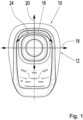
- Fig. 1 shows a joystick 10.
- the joystick comprises a base 12 that is bolted to a deck 14 of a marine vessel. Further, the joystick comprises a stick element 16 that is moveably attached to the base 12.
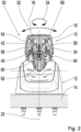
- the stick element 16 is shaped as a cap, which can best be seen in Fig. 2 and Fig. 3 .
- the stick element 16 can be tilted relative to the base 12 in a left-right direction out of a neutral yaw position, which is shown in Figs. 1 to 3 .
- the left-right tilting is illustrated with arrow 18.
- the left-right tilting is a swaying of the joystick 10.
- the stick element 16 can be tilted relative to the base 12 in a forward-backward direction out of the neutral yaw position.
- the forward-backward tilting is illustrated with arrow 20.
- the stick element 16 can be rotated relatively to the base 12 around a central axis 22 of yaw rotation, which corresponds to a longitudinal central axis of the stick element 16 in the shown example.
- the yaw rotation is illustrated with arrow 24.
- the joystick 10 comprises a mounting device 30.
- the mounting device 30 comprises a first mounting element 32, a second mounting element 34, two spring elements 36 and two ball elements 38, as can be seen in the exploded view of Fig. 10 .
- the stick element 16 is attached to the first mounting element 32, for example with screws.
- the second mounting element 34 is fixed to the base 12.
- the two mounting elements 32, 34 are rotatably attached to each other to allow a rotation of the stick element 16 of the joystick 10 about the central axis 22 of yaw rotation out of the neutral yaw position.
- the mounting device 30 comprises a support element 40 and a screw 42 that attaches the two mounting elements 32, 34 relatively rotatable to each other.
- Both mounting elements 32, 34 are injection molded parts.
- the spring elements 36 and the ball elements 38 are standard parts.
- the spring elements 36 are received each in a corresponding blind hole in the first mounting element 32 that are symmetrically arranged in a projection 44 of the first mounting element 32 and parallel to the central axis 22.
- the projection 44 of the first mounting element 32 is arranged in a receptacle 46 formed by the second mounting element 34.
- the receptacle 46 is limited in the radial direction by a side wall 48 of the second mounting element 34.
- the receptacle is closed by the first mounting element 32, which forms a lid for the receptacle 46.
- the spring elements 36 are mounted to the first mounting element 32 and urge each a corresponding one of the ball elements 38 against a ball support surface 50 of the second mounting element 34.
- the ball support surface 50 forms a bottom of the receptacle 46.
- the ball elements 38 are received in the receptacle 46 and rest on the ball support surface 50.
- At least a part of the ball support surface 50 is inclined such that rotation of the stick element 16 about the central axis 22 away from the neutral yaw position causes increase of tension in the spring elements 36 since the ball elements 38 are moved closer to the first mounting element 32 and thus against the spring elements 36, providing a return force for rotating the stick element 16 back into the neutral position upon release of the stick element 16.
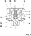
- Fig. 5 shows one of the ball elements 38 resting on a section of the ball support surface 50 corresponding to the neutral yaw position.
- the ball support surface comprises an inclined part inclined toward the first mounting element 32.
- this results in a V-shaped ball support surface 50 with the bottom of the V-shape corresponding to the neutral yaw position.
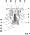
- the inclined part of the ball support surface 50 is at least partially inclined away from the first mounting element 32 in a radial direction relative to the central axis 22. This can best be seen in Fig. 4 and Fig. 7 , showing a downward tilted ball support surface.
- Such a configuration improves smooth movement of the ball elements 38 and therefore the mounting elements 32, 34 relative to each other.
- the ball elements 38 are partially received in the blind hole in which the corresponding spring element 36 is received.
- the first mounting element 32 thus guides the ball elements 38 in the receptacle during yaw movement of the two mounting elements 32, 34 relative to each other, further improving smoothness of movement.
- the side wall 48 of the second mounting element 34 forms an end stop limiting rotation of the stick element 16 of the joystick 10 about the central axis 22 of yaw rotation.
- the side wall 48 has two projections 52 projecting inwards in the receptacle 46.
- the projections 52 are equidistantly spaced apart from the projection 44 of the first mounting element. This can best be seen in Fig. 6 .
- the projection 44 of the first mounting element 32 will rest at least with one side against at least one of the projections 52, which defines an end stop and thus the maximum angle of yaw rotation.
- the projections 52 of the side wall 48 are not equidistantly spaced apart from the projection 44 of the first mounting element 32.
- the projections 52 of the side wall 48 are in contact with one side of the projection 44 of the first mounting element 32 in the neutral yaw position, it is only possible to rotate the stick element 16 in one direction around the central axis 22 of yaw rotation.
- the mounting device comprises an annular rotary seal 54, which can best be seen in Fig. 2 and Fig. 3 .
- the seal 54 rests on ribs 56 of the second mounting element 34 spaced around an outside of the side wall 48.
- the ribs 56 form a discontinuous seal support surface.
- the seal 54 is tightly fitting against the section of the side wall 48 projecting longitudinally beyond the ribs 56 towards the first mounting element 32.
- the seal 54 comprises one annular lip that seals against a ledge 58 of the first mounting element 32 projecting radially.
- the joystick comprises an annular seal 64 having folds. The seal 64 seals between the base 12 and the mounting device 30, in the shown example against the second mounting element 34.
- the joystick 10 comprises a sensor 60 arranged in a longitudinal direction beneath the second mounting element 34, such as a magnet sensor system or potentiometer. Further, the joystick 10 comprises a PCB board 62.
- the sensor 60 is configured to capture a yaw rotation of the stick element 16 or to capture rotation of the two mounting elements 32, 34 relative to each other about the central axis 22 of yaw rotation.
- the PCB board 62 is configured to transmit a sensor signal. Further, in an embodiment, the PCB board 62 is configured to generate a control signal for controlling a thruster of the marine vessel.
- the mounting device 30 uses a lot of standard parts and injection molded parts and may thus be manufactured cost-effectively in high numbers. Further, high forces for returning the stick element 16 in its neutral yaw position may be provided in a very small space. The force may be easily adapted with different spring elements, a different number of spring elements 36 and ball elements 38 different inclinations and different profiles of the ball support surface 50. The mounting device 30 can easily be sealed against a maritime environment.
Landscapes
- Engineering & Computer Science (AREA)
- Physics & Mathematics (AREA)
- General Physics & Mathematics (AREA)
- Automation & Control Theory (AREA)
- Chemical & Material Sciences (AREA)
- Combustion & Propulsion (AREA)
- Mechanical Engineering (AREA)
- Ocean & Marine Engineering (AREA)
- Mechanical Control Devices (AREA)
Priority Applications (2)
| Application Number | Priority Date | Filing Date | Title |
|---|---|---|---|
| EP22200671.0A EP4354249A1 (de) | 2022-10-10 | 2022-10-10 | Stützanordnung für einen joystick zum steuern eines fahrzeugs |
| US18/480,780 US20240116617A1 (en) | 2022-10-10 | 2023-10-04 | Mounting device for a joystick configured for controlling a vehicle |
Applications Claiming Priority (1)
| Application Number | Priority Date | Filing Date | Title |
|---|---|---|---|
| EP22200671.0A EP4354249A1 (de) | 2022-10-10 | 2022-10-10 | Stützanordnung für einen joystick zum steuern eines fahrzeugs |
Publications (1)
| Publication Number | Publication Date |
|---|---|
| EP4354249A1 true EP4354249A1 (de) | 2024-04-17 |
Family
ID=83689639
Family Applications (1)
| Application Number | Title | Priority Date | Filing Date |
|---|---|---|---|
| EP22200671.0A Pending EP4354249A1 (de) | 2022-10-10 | 2022-10-10 | Stützanordnung für einen joystick zum steuern eines fahrzeugs |
Country Status (2)
| Country | Link |
|---|---|
| US (1) | US20240116617A1 (de) |
| EP (1) | EP4354249A1 (de) |
Citations (8)
| Publication number | Priority date | Publication date | Assignee | Title |
|---|---|---|---|---|
| WO2006062416A1 (en) | 2004-12-07 | 2006-06-15 | Cwf Hamilton & Co Limited | Propulsion and control system for a marine vessel |
| JP2006327323A (ja) * | 2005-05-24 | 2006-12-07 | Yazaki Corp | 車両後進指令操作装置および後進指令操作機能を備えた車両変速操作装置 |
| JP2008101903A (ja) * | 2006-10-20 | 2008-05-01 | Leupold & Stevens Inc | 照準器用ポップアップ調整キャップシステム |
| DE102012017122A1 (de) * | 2011-08-31 | 2013-02-28 | Marquardt Gmbh | Elektrischer Schalter |
| US9690295B1 (en) * | 2015-08-20 | 2017-06-27 | Brunswick Corporation | Heading control on a marine vessel |
| JP2017168002A (ja) * | 2016-03-18 | 2017-09-21 | 富士機工株式会社 | 車両用シフト装置 |
| US20210265120A1 (en) * | 2020-02-26 | 2021-08-26 | GE Precision Healthcare LLC | Control device sensor rotation |
| EP3784526B1 (de) * | 2018-04-24 | 2022-04-13 | Merit Poland Spólka Z Ograniczona Odpowiedzialnoscia | Selbstrückstellende drehschalteranordnung, insbesondere eines integrierten lenksäulenmoduls eines kraftfahrzeugs |
Family Cites Families (4)
| Publication number | Priority date | Publication date | Assignee | Title |
|---|---|---|---|---|
| US5893295A (en) * | 1997-07-24 | 1999-04-13 | Bronnert; Hervex. | Motorcycle cruise control |
| DE102005006849A1 (de) * | 2005-02-15 | 2006-08-17 | Om Carrelli Elevatori S.P.A. | Lenkvorrichtung |
| US7267068B2 (en) * | 2005-10-12 | 2007-09-11 | Brunswick Corporation | Method for maneuvering a marine vessel in response to a manually operable control device |
| US8997591B1 (en) * | 2013-08-22 | 2015-04-07 | Rockwell Collins, Inc. | Control knob return/detent mechanism |
-
2022
- 2022-10-10 EP EP22200671.0A patent/EP4354249A1/de active Pending
-
2023
- 2023-10-04 US US18/480,780 patent/US20240116617A1/en not_active Abandoned
Patent Citations (8)
| Publication number | Priority date | Publication date | Assignee | Title |
|---|---|---|---|---|
| WO2006062416A1 (en) | 2004-12-07 | 2006-06-15 | Cwf Hamilton & Co Limited | Propulsion and control system for a marine vessel |
| JP2006327323A (ja) * | 2005-05-24 | 2006-12-07 | Yazaki Corp | 車両後進指令操作装置および後進指令操作機能を備えた車両変速操作装置 |
| JP2008101903A (ja) * | 2006-10-20 | 2008-05-01 | Leupold & Stevens Inc | 照準器用ポップアップ調整キャップシステム |
| DE102012017122A1 (de) * | 2011-08-31 | 2013-02-28 | Marquardt Gmbh | Elektrischer Schalter |
| US9690295B1 (en) * | 2015-08-20 | 2017-06-27 | Brunswick Corporation | Heading control on a marine vessel |
| JP2017168002A (ja) * | 2016-03-18 | 2017-09-21 | 富士機工株式会社 | 車両用シフト装置 |
| EP3784526B1 (de) * | 2018-04-24 | 2022-04-13 | Merit Poland Spólka Z Ograniczona Odpowiedzialnoscia | Selbstrückstellende drehschalteranordnung, insbesondere eines integrierten lenksäulenmoduls eines kraftfahrzeugs |
| US20210265120A1 (en) * | 2020-02-26 | 2021-08-26 | GE Precision Healthcare LLC | Control device sensor rotation |
Also Published As
| Publication number | Publication date |
|---|---|
| US20240116617A1 (en) | 2024-04-11 |
Similar Documents
| Publication | Publication Date | Title |
|---|---|---|
| US10377458B1 (en) | Joystick system for a watercraft | |
| US7320629B2 (en) | Steering device for small watercraft | |
| US8322296B2 (en) | Submersible apparatus including flexible waterproofing membranes | |
| US8046121B2 (en) | Watercraft steering device and watercraft | |
| US8419488B2 (en) | Steering apparatus for outboard motor | |
| US20070068438A1 (en) | Small boat | |
| US7930986B2 (en) | Watercraft steering device and watercraft | |
| EP3569491B1 (de) | Aussenbordmotor | |
| US20080115713A1 (en) | Watercraft steering system | |
| US20240116616A1 (en) | Mounting device for a lever configured for controlling a marine vehicle | |
| US20210291951A1 (en) | Joystick with control members | |
| US20240116617A1 (en) | Mounting device for a joystick configured for controlling a vehicle | |
| US12503211B2 (en) | Outboard motor and marine vessel | |
| JP4994005B2 (ja) | 船舶用操舵装置及び船舶 | |
| JP2006182178A (ja) | アクセル操作装置 | |
| CN108069014A (zh) | 用于预先给定船的电驱动装置的行驶档级的设备 | |
| US5680796A (en) | Manual controller with control lever | |
| US9630696B2 (en) | Outboard motor shift actuator | |
| JP2023068785A (ja) | 船舶推進システムおよび船舶 | |
| EP3718875B1 (de) | System zum manövrieren von booten | |
| US6491555B2 (en) | Throttle grip position maintaining device in outboard engine system | |
| NL2018388B1 (en) | Thruster for propelling a watercraft | |
| EP3693265B1 (de) | Fly-by-wire-lenkradnabe für motorboote | |
| JP4227576B2 (ja) | 船外機の遠隔操作装置 | |
| US20240308636A1 (en) | Engine control apparatus |
Legal Events
| Date | Code | Title | Description |
|---|---|---|---|
| PUAI | Public reference made under article 153(3) epc to a published international application that has entered the european phase |
Free format text: ORIGINAL CODE: 0009012 |
|
| STAA | Information on the status of an ep patent application or granted ep patent |
Free format text: STATUS: REQUEST FOR EXAMINATION WAS MADE |
|
| 17P | Request for examination filed |
Effective date: 20230928 |
|
| AK | Designated contracting states |
Kind code of ref document: A1 Designated state(s): AL AT BE BG CH CY CZ DE DK EE ES FI FR GB GR HR HU IE IS IT LI LT LU LV MC ME MK MT NL NO PL PT RO RS SE SI SK SM TR |
|
| STAA | Information on the status of an ep patent application or granted ep patent |
Free format text: STATUS: THE APPLICATION IS DEEMED TO BE WITHDRAWN |