EP4354396A1 - Korrekturverfahren und -vorrichtung für tiefenbilder und verfahren zur schweissprüfung einer schalenanordnung einer batterie - Google Patents
Korrekturverfahren und -vorrichtung für tiefenbilder und verfahren zur schweissprüfung einer schalenanordnung einer batterie Download PDFInfo
- Publication number
- EP4354396A1 EP4354396A1 EP23735956.7A EP23735956A EP4354396A1 EP 4354396 A1 EP4354396 A1 EP 4354396A1 EP 23735956 A EP23735956 A EP 23735956A EP 4354396 A1 EP4354396 A1 EP 4354396A1
- Authority
- EP
- European Patent Office
- Prior art keywords
- depth image
- battery
- adjacent surfaces
- intersecting line
- datum plane
- Prior art date
- Legal status (The legal status is an assumption and is not a legal conclusion. Google has not performed a legal analysis and makes no representation as to the accuracy of the status listed.)
- Granted
Links
Images


Classifications
-
- G—PHYSICS
- G06—COMPUTING OR CALCULATING; COUNTING
- G06T—IMAGE DATA PROCESSING OR GENERATION, IN GENERAL
- G06T7/00—Image analysis
- G06T7/10—Segmentation; Edge detection
- G06T7/12—Edge-based segmentation
-
- G—PHYSICS
- G06—COMPUTING OR CALCULATING; COUNTING
- G06V—IMAGE OR VIDEO RECOGNITION OR UNDERSTANDING
- G06V10/00—Arrangements for image or video recognition or understanding
- G06V10/20—Image preprocessing
- G06V10/24—Aligning, centring, orientation detection or correction of the image
-
- G—PHYSICS
- G06—COMPUTING OR CALCULATING; COUNTING
- G06T—IMAGE DATA PROCESSING OR GENERATION, IN GENERAL
- G06T7/00—Image analysis
-
- G—PHYSICS
- G06—COMPUTING OR CALCULATING; COUNTING
- G06T—IMAGE DATA PROCESSING OR GENERATION, IN GENERAL
- G06T7/00—Image analysis
- G06T7/0002—Inspection of images, e.g. flaw detection
- G06T7/0004—Industrial image inspection
-
- G—PHYSICS
- G06—COMPUTING OR CALCULATING; COUNTING
- G06T—IMAGE DATA PROCESSING OR GENERATION, IN GENERAL
- G06T7/00—Image analysis
- G06T7/50—Depth or shape recovery
-
- G—PHYSICS
- G06—COMPUTING OR CALCULATING; COUNTING
- G06T—IMAGE DATA PROCESSING OR GENERATION, IN GENERAL
- G06T7/00—Image analysis
- G06T7/60—Analysis of geometric attributes
-
- G—PHYSICS
- G06—COMPUTING OR CALCULATING; COUNTING
- G06T—IMAGE DATA PROCESSING OR GENERATION, IN GENERAL
- G06T2207/00—Indexing scheme for image analysis or image enhancement
- G06T2207/10—Image acquisition modality
- G06T2207/10004—Still image; Photographic image
- G06T2207/10012—Stereo images
-
- G—PHYSICS
- G06—COMPUTING OR CALCULATING; COUNTING
- G06T—IMAGE DATA PROCESSING OR GENERATION, IN GENERAL
- G06T2207/00—Indexing scheme for image analysis or image enhancement
- G06T2207/10—Image acquisition modality
- G06T2207/10028—Range image; Depth image; 3D point clouds
-
- G—PHYSICS
- G06—COMPUTING OR CALCULATING; COUNTING
- G06T—IMAGE DATA PROCESSING OR GENERATION, IN GENERAL
- G06T2207/00—Indexing scheme for image analysis or image enhancement
- G06T2207/30—Subject of image; Context of image processing
- G06T2207/30108—Industrial image inspection
-
- Y—GENERAL TAGGING OF NEW TECHNOLOGICAL DEVELOPMENTS; GENERAL TAGGING OF CROSS-SECTIONAL TECHNOLOGIES SPANNING OVER SEVERAL SECTIONS OF THE IPC; TECHNICAL SUBJECTS COVERED BY FORMER USPC CROSS-REFERENCE ART COLLECTIONS [XRACs] AND DIGESTS
- Y02—TECHNOLOGIES OR APPLICATIONS FOR MITIGATION OR ADAPTATION AGAINST CLIMATE CHANGE
- Y02E—REDUCTION OF GREENHOUSE GAS [GHG] EMISSIONS, RELATED TO ENERGY GENERATION, TRANSMISSION OR DISTRIBUTION
- Y02E60/00—Enabling technologies; Technologies with a potential or indirect contribution to GHG emissions mitigation
- Y02E60/10—Energy storage using batteries
Definitions
- the present application relates to the technical field of batteries, and in particular to a correction method and apparatus for a depth image of a battery, a method for welding inspection of a shell assembly of a battery, a control apparatus, a computer-readable storage medium, and a computer program product.
- a shell assembly of a battery is generally formed by welding between two parts, and after a welding process, welding quality is generally inspected using an image, in which the detection of many defects depends on depth information from a depth image.
- welding quality is generally inspected using an image, in which the detection of many defects depends on depth information from a depth image.
- the camera may have a photographing state that deviates from a desired index, causing certain errors in the depth image. Such errors may seriously affect the accuracy of defect detection results.
- an objective of the present application is to propose a correction method and apparatus for a depth image of a battery, a method for welding inspection of a shell assembly of a battery, a control apparatus, a computer-readable storage medium, and a computer program product, to remove deviations in an image during inspection, thereby improving the accuracy of inspection results for a shell assembly of a battery.
- An embodiment in a first aspect of the present application provides a correction method for a depth image of a battery, including: obtaining a depth image of a battery, where the depth image includes two adjacent surfaces of a shell assembly of the battery and an intersecting line between the two adjacent surfaces; extracting the intersecting line from the depth image; determining planes in the depth image in which the two adjacent surfaces are located; obtaining a datum plane based on the intersecting line and the planes in which the two adjacent surfaces are located, where the datum plane is parallel to the intersecting line, and included angles between the datum plane and the planes in which the two adjacent surfaces are located are equal to each other; and projecting and mapping points in the depth image to the datum plane, to obtain depth information of points in a corrected depth image.
- a datum plane is fitted based on the depth image of the shell assembly of the battery, and the depth information of the depth image is corrected by taking the datum plane as the standard, such that deviations in the depth image caused by the deviation of a photographing state of a camera from a desired index can be avoided, which facilitates inspection of the shell assembly of the battery based on the image, and can improve the accuracy of inspection results for the shell assembly of the battery.
- the fitted datum plane is parallel to the intersecting line, and the included angles between the datum plane and the two adjacent surfaces are equal to each other.
- both the intersecting line and the two adjacent surfaces in the depth image can be projected to the datum plane, such that the entire depth image can be corrected to obtain a fully corrected image of the shell assembly of the battery, for use in inspecting the shell assembly.
- the datum plane is simple in terms of algorithm, which facilitates reducing the amount of computation and improving the efficiency of computation.
- the extracting the intersecting line from the depth image includes: extracting a point with the largest depth value in each row from the depth image; and obtaining an equation of a straight line for the intersecting line based on extracted points.
- the process of extracting the intersecting line is simple, and the obtained equation for the intersecting line is relatively accurate. Therefore, a datum plane obtained based on the intersecting line can also be made relatively reliable, which facilitates improving the accuracy of correcting the depth image based on the datum plane.
- the obtaining an equation of a straight line for the intersecting line based on extracted points includes: analyzing the extracted points by using a principal component analysis algorithm to obtain feature vectors, and obtaining the equation of the straight line based on the feature vectors.
- the equation of the straight line for the intersecting line is simple in terms of calculation mode, and the obtained equation for the intersecting line is relatively accurate. Therefore, a datum plane obtained based on the intersecting line can also be made relatively reliable, which facilitates improving the accuracy of correcting the depth image based on the datum plane.
- the extracting the intersecting line from the depth image further includes: determining whether the equation of the straight line meets a set condition, and if not, performing screening on the extracted points, and re-obtaining an equation of a straight line based on points remained after screening.
- feature points can be further refined such that the accuracy of the feature points can be improved, and the accuracy of a fitted intersecting line can thus be improved.
- the obtaining a datum plane based on the intersecting line and the planes in which the two adjacent surfaces are located includes: calculating feature vectors of the planes in which the two adjacent surfaces are located; and obtaining an equation for the datum plane based on the feature vectors of the planes in which the two adjacent surfaces are located and the equation of the straight line in which the intersecting line is located, where a normal vector to the datum plane is a sum of the feature vectors of the planes in which the two adjacent surfaces are located.
- the datum plane is simple in terms of calculation mode, which facilitates reducing the amount of computation and improving the efficiency of computation.
- the determining planes in the depth image in which the two adjacent surfaces are located includes: determining the planes in which the two adjacent surfaces are located based on the equation of the straight line in which the intersecting line is located.
- the planes in which the two surfaces are located can be obtained more easily, thereby further simplifying the entire depth image correction algorithm.
- An embodiment in a second aspect of the present application provides a method for welding inspection of a shell assembly of a battery, including: acquiring a depth image of a battery, where the battery includes a shell assembly, the shell assembly includes a first portion and a second portion connected to each other by means of welding, the depth image includes two adjacent surfaces of the shell assembly of the battery and an intersecting line between the two adjacent surfaces, and there is a weld bead for the first portion and the second portion on at least one of the two adjacent surfaces; correcting the depth image of the battery by using a correction method for a depth image of a battery of any one of the embodiments described above, to obtain depth information of points in a corrected depth image; and determining a quality of the weld bead based on the depth information of the points in the corrected depth image.
- the depth image of the shell assembly of the battery is corrected such that deviations in the depth image caused by the deviation of a photographing state of a camera from a desired index can be avoided, which facilitates inspection of a weld bead of the shell assembly of the battery, and can improve the accuracy of inspection results for the weld bead of the shell assembly of the battery.
- the acquiring a depth image of a battery includes: photographing the depth image of the battery by a depth camera, where an image acquisition plane of the depth camera forms an inclination angle ⁇ with at least one of the two adjacent surfaces of the shell assembly of the battery, and the inclination angle ⁇ satisfies 30° ⁇ ⁇ ⁇ 60°.
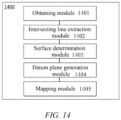
- An embodiment in a third aspect of the present application provides a correction apparatus for a depth image of a battery, including: an obtaining module configured to obtain a depth image of a battery, where the depth image includes two adjacent surfaces of a shell assembly of the battery and an intersecting line between the two adjacent surfaces; an intersecting line extraction module configured to extract the intersecting line from the depth image; a surface determination module configured to determine planes in the depth image in which the two adjacent surfaces are located; a datum plane generation module configured to obtain a datum plane based on the intersecting line and the planes in which the two adjacent surfaces are located, where the datum plane is parallel to the intersecting line, and included angles between the datum plane and the planes in which the two adjacent surfaces are located are equal to each other; and a mapping module configured to project and map points in the depth image to the datum plane, to obtain depth information of points in a corrected depth image.
- a datum plane is fitted based on the depth image of the shell assembly of the battery, and the depth information of the depth image is corrected by taking the datum plane as the standard, such that deviations in the depth image caused by the deviation of a photographing state of a camera from a desired index can be avoided, which facilitates inspection of the shell assembly of the battery based on the image, and can improve the accuracy of inspection results for the shell assembly of the battery.
- the fitted datum plane is parallel to the intersecting line, and the included angles between the datum plane and the two adjacent surfaces are equal to each other.
- both the intersecting line and the two adjacent surfaces in the depth image can be projected to the datum plane, such that the entire depth image can be corrected to obtain a fully corrected image of the shell assembly of the battery, for use in inspecting the shell assembly.
- the datum plane is simple in terms of algorithm, which facilitates reducing the amount of computation and improving the efficiency of computation.
- the intersecting line extraction module is configured to: extract a point with the largest depth value in each row from the depth image; and obtain an equation of a straight line for the intersecting line based on extracted points.
- the process of extracting the intersecting line is simple, and the obtained equation for the intersecting line is relatively accurate. Therefore, a datum plane obtained based on the intersecting line can also be made relatively reliable, which facilitates improving the accuracy of correcting the depth image based on the datum plane.
- the intersecting line extraction module is configured to: analyze the extracted points by using a principal component analysis algorithm to obtain feature vectors, and obtain the equation of the straight line based on the feature vectors.
- the equation of the straight line for the intersecting line is simple in terms of calculation mode, and the obtained equation for the intersecting line is relatively accurate. Therefore, a datum plane obtained based on the intersecting line can also be made relatively reliable, which facilitates improving the accuracy of correcting the depth image based on the datum plane.
- the intersecting line extraction module is further configured to: determine whether the equation of the straight line meets a set condition, and if not, perform screening on the extracted points, and re-obtain an equation of a straight line based on points remained after screening.
- feature points can be further refined such that the accuracy of feature points at the top edge can be improved, and the accuracy of a fitted intersecting line can thus be improved.
- the datum plane generation module is configured to: calculate feature vectors of the planes in which the two adjacent surfaces are located; and obtain an equation for the datum plane based on the feature vectors of the planes in which the two adjacent surfaces are located and the equation of the straight line in which the intersecting line is located, where a normal vector to the datum plane is a sum of the feature vectors of the planes in which the two adjacent surfaces are located.
- the datum plane is simple in terms of calculation mode, which facilitates reducing the amount of computation and improving the efficiency of computation.
- the surface determination module is configured to: determine the planes in which the two adjacent surfaces are located based on the equation of the straight line in which the intersecting line is located.
- the planes in which the two surfaces are located can be obtained more easily, thereby further simplifying the entire depth image correction algorithm.
- An embodiment in a fourth aspect of the present application provides a control apparatus, including: at least one processor; and a memory communicatively coupled to the at least one processor, where the memory stores instructions executable by the at least one processor, and the instructions, when executed by the at least one processor, cause the at least one processor to perform a correction method for a depth image of a battery of any one of the embodiments described above.
- An embodiment in a fifth aspect of the present application provides a computer-readable storage medium storing a computer program that, when executed by a processor, implements a correction method for a depth image of a battery of any one of the embodiments described above.
- An embodiment in a sixth aspect of the present application provides a computer program product including a computer program that, when executed by a processor, implements a correction method for a depth image of a battery of any one of the embodiments described above.
- a plurality of means two or more (including two), similarly the term “a plurality of groups” means two or more groups (including two groups), and the term “a plurality of pieces” means two or more pieces (including two pieces).
- the technical terms such as “install”, “couple”, “connect”, and “fix” should be understood in a broad sense, for example, they may be a fixed connection, a detachable connection, or an integrated connection; may be a mechanical connection or an electric connection; and may be a direct connection or an indirect connection by means of an intermediate medium, or may be communication between interiors of two elements or interaction between the two elements.
- install may be a fixed connection, a detachable connection, or an integrated connection
- traction batteries are used more and more widely.
- the traction batteries are not only used in energy storage power systems such as hydroelectric power plants, thermal power plants, wind power plants and solar power plants, but also widely used in electric transportation means such as electric bicycles, electric motorcycles, and electric vehicles and in many fields such as military equipment and aerospace.
- energy storage power systems such as hydroelectric power plants, thermal power plants, wind power plants and solar power plants
- electric transportation means such as electric bicycles, electric motorcycles, and electric vehicles and in many fields such as military equipment and aerospace.
- the market demand for the traction batteries is also expanding.
- a traction battery includes battery cells.
- a shell assembly of a battery cell is generally formed by connecting two parts (such as a shell and a top cover) by means of welding, and after a welding process, welding quality is generally inspected using an image, in which the detection of many defects depends on depth information from a depth image.
- the applicants have found after research that due to hardware factors of a camera, human errors in mounting, changes in a photographing environment on site, etc., the camera may have a photographing state that deviates from a desired index, causing certain errors in the depth image. Those errors may seriously affect the accuracy of defect detection results.
- an image acquisition plane of the depth camera is parallel to a weld bead, because this facilitates inspecting the quality of the weld bead based on a machine learning method, thereby improving the accuracy of quality inspection of the weld bead.
- a camera is prone to an angular deviation, resulting in deviations in depth information of a depth image, and thus making it difficult to accurately determine the welding quality of a weld bead.
- the weld bead in the depth image has an extension direction that is deviated, and consequently, the weld bead has an increasingly larger depth value along its extension direction, making it difficult to accurately determine the welding quality of the weld bead.
- the applicants made intensive studies and have designed a correction method and apparatus for a depth image of a battery, a method for welding inspection of a shell assembly of a battery, a control apparatus, a computer-readable storage medium, and a computer program product, in order to solve the problem of deviations in the depth image of the battery during acquisition, thereby improving the accuracy of results for inspection of the shell assembly of the battery based on the image.
- the depth information of the acquired depth image of the battery is corrected, and the corrected depth information is used to inspect the quality of the shell assembly of the battery, so as to avoid the problems of a relatively low accuracy quality inspection caused by the deviations in the image during acquisition, etc., thereby making quality inspection results more accurate.
- the battery cell disclosed in the embodiments of the present application may be used in, but is not limited to, a power consuming apparatus, such as a vehicle, a ship, or an aircraft.
- a power system composed of the battery cells, batteries, etc. disclosed in the present application may be used for the power consuming apparatus, which is conducive to avoiding safety problems caused by poor welding of the top cover of the battery cell, thereby improving the performance stability and service life of the battery.
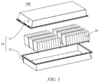
- FIG. 1 is an exploded view of the battery 100 provided in some embodiments of the present application.
- the battery 100 includes a case 10 and battery cells 20.
- the battery cells 20 are accommodated in the case 10.
- the case 10 is configured to provide an accommodation space for the battery cells 20, and the case 10 may be of various structures.
- the case 10 may include a first case portion 11 and a second case portion 12.
- the first case portion 11 and the second case portion 12 are fitted to each other in a covered manner, and the first case portion 11 and the second case portion 12 jointly define the accommodation space for accommodating the battery cell 20.
- the second case portion 12 may be of a hollow structure with one end open; the first case portion 11 may be of a plate-like structure; and the first case portion 11 is fitted to the open side of the second case portion 12 in a covered manner, such that the first case portion 11 and the second case portion 12 jointly define the accommodation space.
- the first case portion 11 and the second case portion 12 each may also be of a hollow structure with one side open, and the open side of the first case portion 11 is fitted to the open side of the second case portion 12 in a covered manner.
- the case 10 formed by the first case portion 11 and the second case portion 12 may be of various shapes, such as a cylinder and a cuboid.
- a plurality of battery cells 20 may be provided.
- the plurality of battery cells 20 may be connected in series, in parallel, or in series and parallel.
- the parallel-series connection means that the plurality of battery cells 20 are connected both in series and in parallel.
- the plurality of battery cells 20 may be directly connected together in series, or in parallel, or in series-parallel, and then a unit composed of the plurality of battery cells 20 is accommodated inside the case 10.
- the battery 100 may also be a unit accommodated in the case 10 that is formed by firstly connecting the plurality of battery cells 20 in series or in parallel or in series and parallel to battery modules, and then connecting the plurality of battery modules in series or in parallel or in series and parallel.
- the battery 100 may further include other structures.
- the battery 100 may further include a busbar component for achieving electrical connections between the plurality of battery cells 20.
- Each battery cell 20 may be a secondary battery or a primary battery, and may also be a lithium-sulfur battery, a sodium-ion battery, or a magnesium-ion battery, but is not limited thereto.
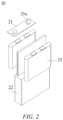
- FIG. 2 is a schematic exploded structural diagram of the battery cell 20 according to some embodiments of the present application.
- the battery cell 20 refers to the smallest unit of the battery.
- the battery cell 20 includes a shell assembly and a cell assembly 23 located in the shell assembly.
- the shell assembly includes a first portion 21 and a second portion 22.
- the first portion 21 of the shell assembly may be a top cover that can be fitted to an opening of the second portion 22 in a covered manner, to isolate an internal environment of the battery cell 20 from an external environment.
- the first portion 21 may be shaped to adapt to the shape of the second portion 22 so as to fit with the second portion 22.
- the first portion 21 may be made of a material (e.g., aluminum alloy) with a certain hardness and strength, and thus the first portion 21 would not easily deform when being squeezed or collided, such that the battery cell 20 can have a higher structural strength, and the safety performance can also be improved.
- the first portion 21 may be provided with functional components such as electrode terminals 21a.
- the electrode terminals 21a may be used for electrical connection to the cell assembly 23 for outputting or inputting electrical energy of the battery cell 20.
- the first portion 21 may further be provided with a pressure relief mechanism, which is configured to release an internal pressure when the internal pressure or temperature of the battery cell 20 reaches a threshold.
- the first portion 21 may also be made of various materials, such as copper, iron, aluminum, stainless steel, aluminum alloy, and plastic, which is not specially limited in the embodiments of the present application.
- the first portion 21 may further be provided with an insulating member on an inner side.
- the insulating member may be configured to isolate electrical connection components inside the second portion 22 from the first portion 21, in order to reduce the risk of a short circuit.
- the insulating member may be made of plastic, rubber, etc.
- the second portion 22 of the shell assembly may be a shell that is configured to fit with the first portion 21 to form the internal environment of the battery cell 20, where the formed internal environment may be used for accommodating the cell assembly 23, an electrolyte, and other components.
- the second portion 22 and the first portion 21 may be independent components, and the second portion 22 may be provided with an opening, at which the first portion 21 is fitted to the opening in a covered manner, to form the internal environment of the battery cell 20.
- the first portion 21 and the second portion 22 may also be integrated. Specifically, the first portion 21 and the second portion 22 may firstly form a common connecting surface before other components are placed into the shell, and then the first portion 21 is fitted to the second portion 22 in a covered manner when the interior of the second portion 22 needs to be packaged.
- the second portion 22 may be made of various materials, such as copper, iron, aluminum, stainless steel, aluminum alloy, and plastic, which is not specially limited in the embodiments of the present application.
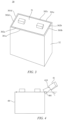
- FIG. 3 is a schematic structural diagram of a battery cell according to some embodiments of the present application.
- a shell assembly 30 is formed by connecting a shell 32 and a top cover 31 by means of welding.
- the shell assembly 30 is prismatic, for example, rectangular, which specifically includes a top surface, a bottom surface, and a plurality of sides.
- the top surface is the surface where the top cover 31 is located, there are a plurality of intersecting lines between the top surface and the plurality of sides of the shell assembly 30, and the plurality of intersecting lines surround the top surface.
- a plurality of weld beads are formed by welding between the shell 32 and the top cover 31, and each weld bead is close to one intersecting line of the shell assembly 30 and substantially parallel to the intersecting line.
- the top surface of the shell assembly 30 forms four intersecting lines 301a, 301b, 301c, and 301d with the four sides of the shell assembly, respectively, four weld beads 302a, 302b, 302c, and 302d are formed by welding between the shell 32 and the top cover 31, and each weld bead is close to one intersecting line of the shell assembly 30 and substantially parallel to the intersecting line.
- the intersecting line 301a is close to the weld bead 302a and substantially parallel to the weld bead 302a
- the intersecting line 301b is close to the weld bead 302b and substantially parallel to the weld bead 302b
- the intersecting line 301c is close to the weld bead 302c and substantially parallel to the weld bead 302c
- the intersecting line 301d is close to the weld bead 302d and substantially parallel to the weld bead 302d.
- FIG. 4 is a schematic diagram of a process of acquiring an image of a shell assembly 40 of a battery by a depth camera according to some embodiments of the present application.
- a CCD line scan camera 41 is used to acquire a depth image of the shell assembly 40 of the battery.
- the CCD line scan camera 41 performs scanning along one intersecting line 401 of the shell assembly 40 to obtain the depth image of the shell assembly 40.
- the depth image of the shell assembly 40 that is obtained after scanning includes the intersecting line 401 and two surfaces adjacent to the intersecting line 401.
- the two surfaces in FIG. 4 are respectively one top surface and one side of the shell assembly.
- the depth image of the shell assembly that is obtained through scanning by using the method of FIG. 4 may be as shown in FIG. 5.
- (a) of FIG. 5 is a depth image of the shell assembly of the battery that is acquired by a depth camera, which is similar to a grayscale image. In the depth image, each pixel value is an actual distance of a sensor from an object, which is specifically represented in grayscale.
- (b) of FIG. 5 is a schematic diagram of a three-dimensional computer graphics corresponding to the depth image (a). In the three-dimensional computer graphics, the depth map is an image or image channel that contains information about a distance from a surface of a scene object of a viewpoint.
- the depth image in FIG. 5 includes one intersecting line 601 of the shell assembly and two surfaces 502 and 503 adjacent to the intersecting line 501.
- FIG. 10 is a flowchart 1000 of a correction method for a depth image of a battery according to some embodiments of the present application.
- FIGS. 6 to 9 are schematic diagrams of a process of correcting a depth image of a battery according to some embodiments of the present application.
- FIG. 6 is a schematic diagram of extracting an intersecting line from a depth image and determining planes in which two adjacent surfaces are located, according to some embodiments of the present application;
- FIG. 7 is a schematic diagram of obtaining a datum plane based on an intersecting line and planes in which two adjacent surfaces are located, according to some embodiments of the present application;
- FIG. 10 is a flowchart 1000 of a correction method for a depth image of a battery according to some embodiments of the present application.
- FIGS. 6 to 9 are schematic diagrams of a process of correcting a depth image of a battery according to some embodiments of the present application.
- FIG. 6 is a schematic diagram of extracting an intersecting line from
- FIG. 8 is a schematic diagram of obtaining a datum plane based on an intersecting line and planes in which two adjacent surfaces are located, according to some other embodiments of the present application; and FIG. 9 is a schematic diagram of projecting points in a depth image to a datum plane according to some embodiments of the present application.
- Some embodiments in a first aspect of the disclosure provide a correction method for a depth image of a battery. As shown in FIG. 10 , the method includes the following steps.
- a depth image of a battery is obtained, where the depth image includes two adjacent surfaces of a shell assembly of the battery and an intersecting line between the two adjacent surfaces.
- the depth image of the shell assembly 40 of the battery can be obtained by the CCD line scan camera 41 by performing scanning.
- the depth image can be obtained by performing scanning along the intersecting line 401 between the two adjacent surfaces of the shell assembly 40.
- the depth image obtained through scanning may be as shown in (a) and (b) of FIG. 5 , in which the two adjacent surfaces 502 and 503 of the shell assembly and the intersecting line 501 between the two surfaces 502 and 503 are included.
- the intersecting line is extracted from the depth image.
- two surfaces in the depth image are located on either side of the intersecting line 601, and points on the two surfaces tend to be lower than the points on the intersecting line 601. Therefore, the two surfaces and planes 602 and 603 in which the two surfaces are respectively located are also easily determined based on the depth image.
- a datum plane is obtained based on the intersecting line and the planes in which the two adjacent surfaces are located, where the datum plane is parallel to the intersecting line, and included angles between the datum plane and the planes in which the two adjacent surfaces are located are equal to each other.
- FIG. 7(a) shows a relative positional relationship of an intersecting line 701, two adjacent surfaces, and the datum plane 700 in a three-dimensional space
- FIG. 7(b) shows a schematic diagram of a cross-section perpendicular to the intersecting line 701 and the datum plane 700.
- the intersecting line 701 is parallel to the datum plane 700 and is located within the datum plane 700
- the two adjacent surfaces are respectively located in planes 702 and 703
- an included angle ⁇ 1 between the datum plane 700 and the plane 702 is equal to an included angle ⁇ 2 between the datum plane 700 and the plane 703.
- the datum plane 700 can be obtained based on the intersecting line 701 and the planes 702 and 703 in which the two surfaces are located.
- FIG. 8(a) shows a relative positional relationship of an intersecting line 801, two adjacent surfaces, and the datum plane 800 in a three-dimensional space
- FIG. 8(b) shows a schematic diagram of a cross-section perpendicular to the intersecting line 801 and the datum plane 800.
- the datum plane 800 is parallel to, that is, does not intersect with, the intersecting line 801; the two adjacent surfaces are respectively located in planes 802 and 803, and an included angle ⁇ 3 between the datum plane 800 and the plane 802 is equal to an included angle ⁇ 4 between the datum plane 800 and the plane 803.
- a plane 800a including the intersecting line 801 can first be obtained based on the intersecting line 801 and the planes 802 and 803 in which the two surfaces are located, and then the datum plane 800 can be obtained by adjusting a constant value of the plane 800a.
- the depth information of the points in the corrected depth image is a height value by which the points in the depth image are projected and mapped to the datum plane.
- each line segment with an arrow in FIG. 9 represents a process of projecting one point in the depth image to a datum plane 900
- the length of each line segment with an arrow is a height value by which one point in the depth image is projected and mapped to the datum plane 900, that is, depth information of one point in the corrected depth image.
- all the points in the depth image may be projected and mapped to the datum plane to obtain corrected depth information for all the points, or only points in some regions may be projected and mapped to the datum plane to obtain corrected depth information for some regions.
- points in some regions including a weld bead are projected and mapped to the datum plane to obtain depth information for some regions including the weld bead, for use in determining the quality of the weld bead. This can be specifically determined according to actual requirements.
- a datum plane is fitted based on the depth image of the shell assembly of the battery, and the depth information of the depth image is corrected by taking the datum plane as the standard, such that deviations in the depth image caused by the deviation of a photographing state of a camera from a desired index can be avoided, which facilitates inspection of the shell assembly of the battery based on the image, and can improve the accuracy of inspection results for the shell assembly of the battery, for example, facilitating determinations of the quality of the weld bead of the shell assembly based on a machine learning method and improving the accuracy of determination results.
- the fitted datum plane is parallel to the intersecting line, and the included angles between the datum plane and the two adjacent surfaces are equal to each other. In this way, both the intersecting line and the two adjacent surfaces in the depth image can be projected to the datum plane, such that the entire depth image can be corrected to obtain a fully corrected image of the shell assembly of the battery, for use in inspecting the shell assembly.
- the datum plane is simple in terms of algorithm, which facilitates reducing the amount of computation and improving the efficiency of computation.
- extracting the intersecting line from the depth image in S 1002 may include the following steps.
- the depth image is obtained by a CCD line scan camera by performing scanning in an extension direction of the intersecting line 501, where an axis Y is parallel to a scanning direction of the depth image, which is a column direction of a pixel; an X axis is perpendicular to the scanning direction of the depth image, which is a row direction of the pixel; and each row of the depth image includes each row of pixel points parallel to the X axis.
- Each row of pixel points includes a point on an intersecting line, and the point on the intersecting line tends to have a larger depth value than those of other points. Therefore, a point with the largest depth value in each row is often the point on the intersecting line.
- the point with the largest depth value in each row is often the point on the intersecting line, and points with the largest depth value in all rows are extracted to obtain a set of points.
- a intersecting line can be fitted through the set of points.
- FIG. 11 is a schematic diagram of the principle of extracting an intersecting line from a depth image according to some embodiments of the present application.
- a set of points shown, for example, in FIG. 11(a) can be obtained by selecting points with the largest depth value in all rows from the image, an intersecting line and an equation of a straight line in which the intersecting line is located can be fitted based on the obtained set of points.
- an equation 110 of a straight line for the intersecting line can be obtained based on processes shown in (b) and (c) of FIG. 11 .
- the process of extracting the intersecting line is simple, and the obtained equation for the intersecting line is relatively accurate. Therefore, a datum plane obtained based on the intersecting line can also be made relatively reliable, which facilitates improving the accuracy of correcting the depth image based on the datum plane.
- obtaining an equation of a straight line for the intersecting line based on extracted points in S10022 may include analyzing the extracted points by using a principal component analysis (PCA) algorithm to obtain feature vectors, and obtaining the equation of the straight line based on the feature vectors.
- PCA principal component analysis
- the equation of the straight line for the intersecting line is simple in terms of calculation mode, and the obtained equation for the intersecting line is relatively accurate. Therefore, a datum plane obtained based on the intersecting line can also be made relatively reliable, which facilitates improving the accuracy of correcting the depth image based on the datum plane.
- extracting the intersecting line from the depth image in S1002 may further include the following step.
- determining whether the equation of the straight line meets the set condition can specifically involve determining whether the equation of the straight line is within an error range in respect of the slope and/or intercept of the equation of the straight line, that is, determining whether the set condition is met. If the slope and/or intercept of the equation of the straight line is within the error range, the set condition is met and the equation of the straight line can be output, otherwise screening is performed on the points, and an equation of a straight line is refitted based on points remained after screening. Exemplarily, the points remained after screening can also be fitted using the PCA technique, to obtain the equation of the straight line.
- the determination of whether the obtained equation of the straight line meets the set condition can be continued in the manner of S10023, to determine whether there is a need to continue point screening and refitting of the equation of the straight line, and so on, until the obtained equation of the straight line meets the set condition (for example, the slope and/or intercept is within the error range), the cycle stops, and the equation of the straight line is output.
- the conditions for stopping the cycle further include the number of times of screening exceeding a set upper limit, or the remaining number of feature points being not sufficient for fitting the equation of the straight line using the PCA technique.
- the refinement is carried out to screen out the outliers, such that a more accurate intersecting line can be finally obtained.
- a feature vector 120 is obtained based on points (including white outliers) extracted from the depth image by using the PCA technique, and there is a certain distance between the feature vector 120 and an intersecting line 110. Therefore, an intersecting line obtained based on the feature vector 120 has a certain deviation with a low accuracy.
- the white outliers in FIG. 11(b) can be discarded, with only black points remained, as shown in FIG. 11(c) , and the intersecting line 110 is refitted based on the remained black points by using the PCA technique. At this time, a more accurate intersecting line 110 is obtained.
- the screening conditions and the outliers that need to be discarded can be defined based on the direction of the feature vector and the mean of the points, and then an equation of a straight line is re-obtained based on the remaining points.
- FIG. 12 is a schematic diagram of the principle of feature point screening according to some embodiments of the present application.
- the depth image has a pixel row direction that is parallel to the X axis, and the depth image has a pixel column direction that is parallel to the Y axis.
- a set condition is that an inclination angle of an intersecting line with respect to the X axis is greater than or equal to 85° and less than or equal to 105°. If an included angle between a fitted intersecting line and the X axis is within this range, feature point screening is not performed. If the included angle between the fitted intersecting line and the X axis is out of this range, the outliers can be discarded based on a relationship between the straight line and the point.
- a screening condition can be set such that: points that satisfy K*X + bais >Y are discarded, and points that satisfy K*X + bais ⁇ Y are retained.
- an inclination angle ⁇ 1 of a straight line with respect to the X axis is less than 85°, which indicates that the set condition is not met and screening is needed. Then, white points in FIG. 12(a) can be discarded according to the above screening condition, with only black points remained after screening, and a more accurate intersecting line refitted based on the black points is obtained.
- an inclination angle ⁇ 2 of a straight line with respect to the X axis is greater than 105°, which indicates that the set condition is not met and screening is needed. Then, white points in FIG. 12(b) can be discarded according to the above screening condition, with only black points remained after screening, and a more accurate intersecting line refitted using the black points is obtained.
- the set condition in this embodiment is merely an example, and the selection of the set condition is not limited thereto, but can be accomplished according to an actual photographing state and an obtained depth image.
- the screening method for feature points is also not limited to the above embodiments, and other screening methods can also be used to refine the feature points.
- feature points can be further refined such that the accuracy of the feature points can be improved, and the accuracy of a fitted intersecting line can thus be improved.
- the determining planes in the depth image in which the two adjacent surfaces are located in S 1003 includes: determining the planes in which the two adjacent surfaces are located based on the equation of the straight line in which the intersecting line is located.
- the depth image can be easily split into two regions based on an equation of a straight line for the intersecting line 601, and then planes 602 and 603 in which the two surfaces are located are respectively fitted based on points in the two regions.
- the method for determining the two surfaces is not limited to the use of the intersecting line.
- this embodiment allows for the planes in which the two surfaces are located to be determined more easily and efficiently using the information of the intersecting line.
- the planes in which the two surfaces are located can be obtained more easily, thereby further simplifying the entire depth image correction algorithm.
- obtaining a datum plane based on the intersecting line and the planes in which the two adjacent surfaces are located in S1004 may include the following steps.
- feature vectors of the planes in which the two adjacent surfaces are located are calculated. For example, in FIG. 7(a) , the two adjacent surfaces are respectively located in planes 702 and 703, the plane 702 has a feature vector V1, and the plane 703 has a feature vector V2.
- the two planes 702 and 703 in which the two surfaces are located can be respectively decomposed using a singular value decomposition (SVD) algorithm, to obtain the respective feature vectors V1 and V2 of the two planes 702 and 703.
- SMD singular value decomposition
- an equation for the datum plane is obtained based on the feature vectors of the planes in which the two adjacent surfaces are located and the equation of the straight line in which the intersecting line is located, where a normal vector to the datum plane is a sum of the feature vectors of the planes in which the two adjacent surfaces are located.
- the included angles ⁇ 1 and ⁇ 2 between the datum plane 700 and the planes 702 and 703 in which the two surfaces are located are respectively equal to 45 degrees.
- a plane can be obtained based on the normal vector V and any point on a straight line in which the intersecting line 701 is located, and the intersecting line 701 is located in the plane.
- the plane can be directly used as the datum plane 700.
- a normal vector V0 to a datum plane 800 is obtained based on feature vectors V3 and V4 of planes 802 and 803 in which two adjacent surfaces are located, and a plane 800a can be obtained based on the normal vector V0 and any point on a straight line in which an intersecting line 801 is located, where the intersecting line 801 is located within the plane 800a.
- the datum plane 800 can be obtained by adjusting a constant value of the plane 800a.
- the datum plane 800 is parallel to the plane 800a, and there is a set difference between constant values of the two planes.
- the method for obtaining the datum plane based on the intersecting line and the planes in which the two adjacent surfaces are located is not limited to this embodiment.
- the datum plane is simple in terms of calculation mode, which facilitates reducing the amount of computation and improving the efficiency of computation.
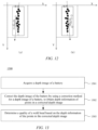
- FIG. 13 is a flowchart 1300 of a method for welding inspection of a shell assembly of a battery according to some embodiments of the present application.
- Some embodiments in a second aspect of the disclosure provide a method for welding inspection of a shell assembly of a battery. As shown in FIG. 13 , the method includes the following steps.
- the battery includes a shell assembly, and the shell assembly includes a first portion and a second portion connected to each other by means of welding.
- the first portion 21 and the second portion 22 of the shell assembly are respectively a top cover and a shell, and the first portion 21 and the second portion 22 are connected to each other by means of welding.
- a plurality of weld beads 302a, 302b, 302c, and 302d are formed when the top cover and the shell are connected to each other by means of welding.
- a depth camera is used to photograph each weld bead, for use in determining the quality of each weld bead.
- the CCD line scan camera 41 when a CCD line scan camera 41 is used to photograph one weld bead 402 on the shell assembly 40, the CCD line scan camera 41 performs scanning along an intersecting line 401 substantially parallel to the weld bead 402 to obtain the depth image of the shell assembly.
- the depth image obtained after scanning can be as shown in FIG. 5(a) .
- the acquired depth image includes two adjacent surfaces of the shell assembly of the battery and an intersecting line between the two adjacent surfaces, and there is a weld bead for the first portion and the second portion on at least one of the two adjacent surfaces.
- the depth image includes two adjacent surfaces 502 and 503 of the shell assembly and an intersecting line 501 between the two adjacent surfaces 502 and 503, and there is a weld bead (not shown) on one of the two adjacent surfaces 502 and 503.
- the weld bead is a weld bead formed by welding between the first portion and the second portion of the shell assembly.
- the shell assembly of the battery is not limited to being formed by the shell and the top cover in FIG. 2 , and can also be formed by a combination of two parts of a shell that have substantially the same shape.
- the weld bead is not limited to being located on the top surface of the shell assembly, for example, the weld bead can also be located on a side of the shell assembly.
- the depth image of the battery is corrected using a correction method for a depth image of a battery of any one of the embodiments described above, to obtain depth information of points in a corrected depth image.
- the corrected depth image includes a weld bead.
- a quality of the weld bead is determined based on the depth information of the points in the corrected depth image.
- the quality of the weld bead is determined using a machine learning method.
- the depth image of the shell assembly of the battery is corrected such that deviations in the depth image caused by the deviation of a photographing state of a camera from a desired index can be avoided, which facilitates inspection of a weld bead of the shell assembly of the battery, and can improve the accuracy of inspection results for the weld bead of the shell assembly of the battery, for example, facilitating determinations of the quality of the weld bead based on a machine learning method and improving the accuracy of determination results.
- the technical solution of the present application provides a simple and effective correction algorithm, which can improve the efficiency of inspecting the weld bead of the shell assembly.
- the acquiring a depth image of a battery in S 1301 includes: photographing the depth image of the battery by means of a depth camera, where an image acquisition plane of the depth camera forms an inclination angle ⁇ with at least one of the two adjacent surfaces of the shell assembly of the battery, and the inclination angle ⁇ satisfies 30° ⁇ ⁇ ⁇ 60°.
- the depth camera is a CCD line scan camera 41
- the image acquisition plane (target surface) 410 of the CCD line scan camera 41 faces an intersecting line 401 of the shell assembly 40, and has an inclination angle ⁇ with a top surface of the shell assembly.
- an included angle ⁇ between the image acquisition plane and one of the two adjacent surfaces is ⁇ 30°
- an included angle between the image acquisition plane and the other of the two adjacent surfaces is larger, and feature information (for example, a weld bead) on the other surface is not easily collected.
- image information is obtained with large distortion, which makes it difficult to implement accurate analysis and inspection.
- an included angle ⁇ between the image acquisition plane and one of the two adjacent surfaces is > 60°, feature information (for example, a weld bead) on this surface is not easily collected.
- image information is obtained with large distortion, which makes it difficult to implement accurate analysis and inspection.
- correction method for a depth image of a battery provided in the present application is not limited to being applied to inspection of the weld bead of the shell assembly, and may also be applied to inspection of the shell assembly in other aspects.
- FIG. 14 is a structural block diagram of a correction apparatus 1400 for a depth image of a battery according to some embodiments of the present application.
- Some embodiments in a third aspect of the disclosure provide a correction apparatus 1400 for a depth image of a battery. As shown in FIG. 14 , the apparatus 1400 includes:
- a datum plane is fitted based on the depth image of the shell assembly of the battery, and the depth information of the depth image is corrected by taking the datum plane as the standard, such that deviations in the depth image caused by the deviation of a photographing state of a camera from a desired index can be avoided, which facilitates inspection of the shell assembly of the battery based on the image, and can improve the accuracy of inspection results for the shell assembly of the battery, for example, facilitating determinations of the quality of the weld bead of the shell assembly based on a machine learning method and improving the accuracy of determination results.
- the fitted datum plane is parallel to the intersecting line, and the included angles between the datum plane and the two adjacent surfaces are equal to each other. In this way, both the intersecting line and the two adjacent surfaces in the depth image can be projected to the datum plane, such that the entire depth image can be corrected to obtain a fully corrected image of the shell assembly of the battery, for use in inspecting the shell assembly.
- the datum plane is simple in terms of algorithm, which facilitates reducing the amount of computation and improving the efficiency of computation.
- the intersecting line extraction module is configured to: extract a point with the largest depth value in each row from a 3D image, and obtain an equation of a straight line for the intersecting line based on extracted points.
- the process of extracting the intersecting line is simple, and the obtained equation for the intersecting line is relatively accurate. Therefore, a datum plane obtained based on the intersecting line can also be made relatively reliable, which facilitates improving the accuracy of correcting the depth image based on the datum plane.
- the intersecting line extraction module may analyze the extracted points by using a principal component analysis algorithm to obtain feature vectors, and obtain the equation of the straight line based on the feature vectors.
- the equation of the straight line for the intersecting line is simple in terms of calculation mode, and the obtained equation for the intersecting line is relatively accurate. Therefore, a datum plane obtained based on the intersecting line can also be made relatively reliable, which facilitates improving the accuracy of correcting the depth image based on the datum plane.
- the intersecting line extraction module is further configured to: determine whether the equation of the straight line meets a set condition, and if not, perform screening on the points, and re-obtain an equation of a straight line based on points remained after screening.
- feature points can be further refined such that the accuracy of the feature points can be improved, and the accuracy of a fitted intersecting line can thus be improved.
- the surface determination module is configured to determine the planes in which the two adjacent surfaces are located based on the equation for the straight line in which the intersecting line is located.
- the planes in which the two surfaces are located can be obtained more easily, thereby further simplifying the entire depth image correction algorithm.
- the datum plane generation module is configured to: calculate feature vectors of the planes in which the two adjacent surfaces are located; and obtain an equation for the datum plane based on the feature vectors of the planes in which the two adjacent surfaces are located and the equation of the straight line in which the intersecting line is located, where a normal vector to the datum plane is a sum of the feature vectors of the planes in which the two adjacent surfaces are located.
- the datum plane is simple in terms of calculation mode, which facilitates reducing the amount of computation and improving the efficiency of computation.
- the correction apparatus for a depth image of a battery according to the embodiments of the disclosure is implemented in the same or similar embodiments and brings about the same or similar beneficial effects, which will not be repeated here.
- Some embodiments in a fourth aspect of the disclosure provide a control apparatus, which includes a memory, a processor, and a program stored on the memory and executable on the processor, where the program, when executed by the processor, implements the correction method for a depth image of a battery of any one of the embodiments described above.
- Various implementations of the systems and technologies described herein above can be implemented in a digital electronic circuit system, an integrated circuit system, a field programmable gate array (FPGA), an application-specific integrated circuit (ASIC), an application-specific standard product (ASSP), a system-on-chip (SOC) system, a complex programmable logical device (CPLD), computer hardware, firmware, software, and/or a combination thereof.
- FPGA field programmable gate array
- ASIC application-specific integrated circuit
- ASSP application-specific standard product
- SOC system-on-chip
- CPLD complex programmable logical device
- computer hardware firmware, software, and/or a combination thereof.
- the programmable processor may be a dedicated or general-purpose programmable processor that can receive data and instructions from a storage system, at least one input apparatus, and at least one output apparatus, and transmit data and instructions to the storage system, the at least one input apparatus, and the at least one output apparatus.
- Some embodiments in a fifth aspect of the disclosure provide a computer-readable storage medium storing a computer program that, when executed by a processor, implements the correction method for a depth image of a battery of any one of the embodiments described above.
- the computer-readable medium may be a tangible medium, which may contain or store a program for use by an instruction execution system, apparatus, or device, or for use in combination with the instruction execution system, apparatus, or device.
- the machine-readable medium may be a machine-readable signal medium or a machine-readable storage medium.
- the machine-readable medium may include, but is not limited to, an electronic, magnetic, optical, electromagnetic, infrared, or semiconductor system, apparatus, or device, or any suitable combination thereof.
- machine-readable storage medium may include an electrical connection based on one or more wires, a portable computer disk, a hard disk, a random access memory (RAM), a read-only memory (ROM), an erasable programmable read-only memory (EPROM or flash memory), an optical fiber, a portable compact disk read-only memory (CD-ROM), an optical storage device, a magnetic storage device, or any suitable combination thereof.
- RAM random access memory
- ROM read-only memory
- EPROM or flash memory erasable programmable read-only memory
- CD-ROM compact disk read-only memory
- magnetic storage device or any suitable combination thereof.
- Some embodiments in a sixth aspect of the disclosure provide a computer program product including a computer program that, when executed by a processor, implements the correction method for a depth image of a battery of any one of the embodiments described above.
- Program codes used to implement the method of the disclosure can be written in any combination of one or more programming languages. These program codes may be provided for a processor or a controller of a general-purpose computer, a special-purpose computer, or other programmable data processing apparatuses, such that when the program codes are executed by the processor or the controller, the functions/operations specified in the flowcharts and/or block diagrams are implemented.
Landscapes
- Engineering & Computer Science (AREA)
- Physics & Mathematics (AREA)
- General Physics & Mathematics (AREA)
- Theoretical Computer Science (AREA)
- Computer Vision & Pattern Recognition (AREA)
- Quality & Reliability (AREA)
- Multimedia (AREA)
- Geometry (AREA)
- Sealing Battery Cases Or Jackets (AREA)
- Length Measuring Devices By Optical Means (AREA)
Applications Claiming Priority (2)
| Application Number | Priority Date | Filing Date | Title |
|---|---|---|---|
| CN202210998618.6A CN115830096B (zh) | 2022-08-19 | 2022-08-19 | 深度图像的校正方法及装置、电池外壳组件焊接检测方法 |
| PCT/CN2023/082805 WO2024036951A1 (zh) | 2022-08-19 | 2023-03-21 | 深度图像的校正方法及装置、电池外壳组件焊接检测方法 |
Publications (3)
| Publication Number | Publication Date |
|---|---|
| EP4354396A1 true EP4354396A1 (de) | 2024-04-17 |
| EP4354396A4 EP4354396A4 (de) | 2024-11-27 |
| EP4354396B1 EP4354396B1 (de) | 2025-04-09 |
Family
ID=85523133
Family Applications (1)
| Application Number | Title | Priority Date | Filing Date |
|---|---|---|---|
| EP23735956.7A Active EP4354396B1 (de) | 2022-08-19 | 2023-03-21 | Verfahren und vorrichtung zur tiefenbildkorrektur und schweissnahterkennungsverfahren für eine batteriegehäusebaugruppe |
Country Status (5)
| Country | Link |
|---|---|
| US (1) | US12374072B2 (de) |
| EP (1) | EP4354396B1 (de) |
| CN (1) | CN115830096B (de) |
| ES (1) | ES3034392T3 (de) |
| WO (1) | WO2024036951A1 (de) |
Families Citing this family (2)
| Publication number | Priority date | Publication date | Assignee | Title |
|---|---|---|---|---|
| DE102022118582B4 (de) * | 2022-07-25 | 2025-07-31 | Carl Zeiss Industrielle Messtechnik Gmbh | Computerimplementiertes Verfahren zum Erzeugen eines korrigierten Bildes mit erweiterter Schärfentiefe, Verfahren, Messgerät und Computerprogrammprodukt |
| CN119681422A (zh) * | 2023-09-15 | 2025-03-25 | 宁德时代新能源科技股份有限公司 | 焊接设备和焊接方法 |
Family Cites Families (12)
| Publication number | Priority date | Publication date | Assignee | Title |
|---|---|---|---|---|
| JP5460149B2 (ja) * | 2009-07-06 | 2014-04-02 | 新日鉄住金エンジニアリング株式会社 | 鋼管突合せ溶接部内面検査装置および方法 |
| TWI572846B (zh) * | 2015-09-18 | 2017-03-01 | 國立交通大學 | 全景影像三維深度估測系統及全景影像三維深度估測方法 |
| CN109813727B (zh) * | 2018-12-25 | 2021-08-03 | 苏州江奥光电科技有限公司 | 一种基于深度信息的pcb板焊接缺陷检测方法 |
| CN111862181A (zh) * | 2019-04-25 | 2020-10-30 | 中国科学院沈阳自动化研究所 | 一种缝隙宽度和阶差检测方法 |
| CN111462110B (zh) * | 2020-04-20 | 2021-04-13 | 广东利元亨智能装备股份有限公司 | 焊缝质量检测方法、装置、系统及电子设备 |
| CN111669557B (zh) * | 2020-06-24 | 2022-05-13 | 歌尔光学科技有限公司 | 投影图像校正方法和校正装置 |
| CN111968183B (zh) | 2020-08-17 | 2022-04-05 | 西安交通大学 | 一种用于单目线激光三维测量模块标定的量块标定法 |
| CN113042939B (zh) * | 2021-03-22 | 2022-06-28 | 山东大学 | 基于三维视觉信息的工件焊缝定位方法及系统 |
| JP7503528B2 (ja) * | 2021-08-03 | 2024-06-20 | 株式会社神戸製鋼所 | 溶接線生成装置、該方法および該プログラム |
| CN113763350B (zh) * | 2021-09-03 | 2024-05-21 | 苏州凌云光工业智能技术有限公司 | 一种胶线检测方法、装置、胶线检测设备及存储介质 |
| CN114119464B (zh) * | 2021-10-08 | 2023-06-16 | 厦门微亚智能科技有限公司 | 一种基于深度学习的锂电池电芯顶盖焊缝外观检测方法 |
| CN113936004B (zh) * | 2021-12-20 | 2022-03-18 | 浙江双元科技股份有限公司 | 一种锂电池焊接质量检测方法、装置及系统 |
-
2022
- 2022-08-19 CN CN202210998618.6A patent/CN115830096B/zh active Active
-
2023
- 2023-03-21 ES ES23735956T patent/ES3034392T3/es active Active
- 2023-03-21 WO PCT/CN2023/082805 patent/WO2024036951A1/zh not_active Ceased
- 2023-03-21 EP EP23735956.7A patent/EP4354396B1/de active Active
- 2023-07-31 US US18/361,916 patent/US12374072B2/en active Active
Also Published As
| Publication number | Publication date |
|---|---|
| EP4354396A4 (de) | 2024-11-27 |
| CN115830096B (zh) | 2023-08-25 |
| CN115830096A (zh) | 2023-03-21 |
| EP4354396B1 (de) | 2025-04-09 |
| US20240062336A1 (en) | 2024-02-22 |
| ES3034392T3 (en) | 2025-08-18 |
| WO2024036951A1 (zh) | 2024-02-22 |
| US12374072B2 (en) | 2025-07-29 |
Similar Documents
| Publication | Publication Date | Title |
|---|---|---|
| EP4336443B1 (de) | Verfahren und vorrichtung zur erkennung von defekten der oberfläche einer batteriezelle | |
| US12374072B2 (en) | Correction method and apparatus for depth image, and method for welding inspection of shell assembly of battery | |
| US20240077432A1 (en) | Cell detection method, apparatus, and system, computer device, and storage medium | |
| CN117280513A (zh) | 电池极片绝缘涂层缺陷的检测方法、装置和计算机设备 | |
| US12307719B2 (en) | Calibration scale, calibration method and apparatus, and detection method and apparatus | |
| KR101515955B1 (ko) | 분석 장치 및 분석 방법 | |
| EP4350621A1 (de) | Verfahren und vorrichtung zur inspektion des aussehens von blanken zellen, computervorrichtung und speichermedium | |
| US12631575B2 (en) | Battery defect inspection device, method, and apparatus | |
| CN115837541B (zh) | 电芯极柱定位方法及装置、焊接方法及装置、设备和介质 | |
| KR20220087027A (ko) | 전지셀 검사 시스템 및 전지셀 검사 방법 | |
| EP4343691A1 (de) | Trainingsverfahren und trainingsvorrichtung für ein fehlererkennungsmodell einer batteriezelle | |
| ES3034926T3 (en) | Method and apparatus for inspecting tab appearance of battery cell assembly, and electronic device | |
| CN117704968B (zh) | 一种基于图像投影的锂电卷绕OverHang检测方法及系统 | |
| WO2024109396A1 (zh) | 转接片的检测方法、装置、电池单体的生产方法和设备 | |
| KR101767707B1 (ko) | 전해액 함침성 측정방법 | |
| CN118229675B (zh) | 电芯检测方法及系统 | |
| CN113963069A (zh) | 一种跳线与铁塔间的测距方法、系统、计算机及存储介质 | |
| CN117642621A (zh) | 用于电池生产的检测方法和系统、电池的生产方法和系统 | |
| CN115839680A (zh) | 电池表面平面度的检测方法、涂胶方法、装置和介质 | |
| CN120031877B (zh) | 电池包外观缺陷检测方法、装置、设备、介质及程序产品 | |
| CN115063414B (zh) | 锂电池极片胶纸的检测方法、装置、设备及存储介质 | |
| CN119251128A (zh) | 图像检测模型及其训练方法、电池检测方法和设备 | |
| CN121540636A (zh) | 极耳翻折检测方法、检测装置、电子设备及可读存储介质 | |
| US20250326068A1 (en) | Quality test method and quality test system | |
| US20240221147A1 (en) | Quality inspection method and apparatus and production method and device for connecting piece, and medium |
Legal Events
| Date | Code | Title | Description |
|---|---|---|---|
| STAA | Information on the status of an ep patent application or granted ep patent |
Free format text: STATUS: UNKNOWN |
|
| STAA | Information on the status of an ep patent application or granted ep patent |
Free format text: STATUS: THE INTERNATIONAL PUBLICATION HAS BEEN MADE |
|
| PUAI | Public reference made under article 153(3) epc to a published international application that has entered the european phase |
Free format text: ORIGINAL CODE: 0009012 |
|
| STAA | Information on the status of an ep patent application or granted ep patent |
Free format text: STATUS: REQUEST FOR EXAMINATION WAS MADE |
|
| 17P | Request for examination filed |
Effective date: 20230712 |
|
| AK | Designated contracting states |
Kind code of ref document: A1 Designated state(s): AL AT BE BG CH CY CZ DE DK EE ES FI FR GB GR HR HU IE IS IT LI LT LU LV MC ME MK MT NL NO PL PT RO RS SE SI SK SM TR |
|
| RAP1 | Party data changed (applicant data changed or rights of an application transferred) |
Owner name: CONTEMPORARY AMPEREX TECHNOLOGY(HONG KONG) LIMITED |
|
| A4 | Supplementary search report drawn up and despatched |
Effective date: 20241025 |
|
| RIC1 | Information provided on ipc code assigned before grant |
Ipc: G06T 7/12 20170101ALI20241021BHEP Ipc: G06T 7/00 20170101ALI20241021BHEP Ipc: G06T 7/60 20170101AFI20241021BHEP |
|
| GRAP | Despatch of communication of intention to grant a patent |
Free format text: ORIGINAL CODE: EPIDOSNIGR1 |
|
| STAA | Information on the status of an ep patent application or granted ep patent |
Free format text: STATUS: GRANT OF PATENT IS INTENDED |
|
| INTG | Intention to grant announced |
Effective date: 20250124 |
|
| RIN1 | Information on inventor provided before grant (corrected) |
Inventor name: JIANG, GUANNAN Inventor name: SHU, ANNAN Inventor name: YUAN, CHAO |
|
| GRAS | Grant fee paid |
Free format text: ORIGINAL CODE: EPIDOSNIGR3 |
|
| GRAA | (expected) grant |
Free format text: ORIGINAL CODE: 0009210 |
|
| STAA | Information on the status of an ep patent application or granted ep patent |
Free format text: STATUS: THE PATENT HAS BEEN GRANTED |
|
| AK | Designated contracting states |
Kind code of ref document: B1 Designated state(s): AL AT BE BG CH CY CZ DE DK EE ES FI FR GB GR HR HU IE IS IT LI LT LU LV MC ME MK MT NL NO PL PT RO RS SE SI SK SM TR |
|
| DAV | Request for validation of the european patent (deleted) | ||
| DAX | Request for extension of the european patent (deleted) | ||
| REG | Reference to a national code |
Ref country code: GB Ref legal event code: FG4D |
|
| REG | Reference to a national code |
Ref country code: CH Ref legal event code: EP |
|
| REG | Reference to a national code |
Ref country code: DE Ref legal event code: R096 Ref document number: 602023002854 Country of ref document: DE |
|
| REG | Reference to a national code |
Ref country code: IE Ref legal event code: FG4D |
|
| P01 | Opt-out of the competence of the unified patent court (upc) registered |
Free format text: CASE NUMBER: APP_19264/2025 Effective date: 20250422 |
|
| REG | Reference to a national code |
Ref country code: NL Ref legal event code: MP Effective date: 20250409 |
|
| REG | Reference to a national code |
Ref country code: ES Ref legal event code: FG2A Ref document number: 3034392 Country of ref document: ES Kind code of ref document: T3 Effective date: 20250818 |
|
| PG25 | Lapsed in a contracting state [announced via postgrant information from national office to epo] |
Ref country code: NL Free format text: LAPSE BECAUSE OF FAILURE TO SUBMIT A TRANSLATION OF THE DESCRIPTION OR TO PAY THE FEE WITHIN THE PRESCRIBED TIME-LIMIT Effective date: 20250409 |
|
| REG | Reference to a national code |
Ref country code: AT Ref legal event code: MK05 Ref document number: 1784234 Country of ref document: AT Kind code of ref document: T Effective date: 20250409 |
|
| PG25 | Lapsed in a contracting state [announced via postgrant information from national office to epo] |
Ref country code: FI Free format text: LAPSE BECAUSE OF FAILURE TO SUBMIT A TRANSLATION OF THE DESCRIPTION OR TO PAY THE FEE WITHIN THE PRESCRIBED TIME-LIMIT Effective date: 20250409 Ref country code: PT Free format text: LAPSE BECAUSE OF FAILURE TO SUBMIT A TRANSLATION OF THE DESCRIPTION OR TO PAY THE FEE WITHIN THE PRESCRIBED TIME-LIMIT Effective date: 20250811 |
|
| REG | Reference to a national code |
Ref country code: LT Ref legal event code: MG9D |
|
| PG25 | Lapsed in a contracting state [announced via postgrant information from national office to epo] |
Ref country code: NO Free format text: LAPSE BECAUSE OF FAILURE TO SUBMIT A TRANSLATION OF THE DESCRIPTION OR TO PAY THE FEE WITHIN THE PRESCRIBED TIME-LIMIT Effective date: 20250709 Ref country code: GR Free format text: LAPSE BECAUSE OF FAILURE TO SUBMIT A TRANSLATION OF THE DESCRIPTION OR TO PAY THE FEE WITHIN THE PRESCRIBED TIME-LIMIT Effective date: 20250710 |
|
| PG25 | Lapsed in a contracting state [announced via postgrant information from national office to epo] |
Ref country code: PL Free format text: LAPSE BECAUSE OF FAILURE TO SUBMIT A TRANSLATION OF THE DESCRIPTION OR TO PAY THE FEE WITHIN THE PRESCRIBED TIME-LIMIT Effective date: 20250409 |
|
| PG25 | Lapsed in a contracting state [announced via postgrant information from national office to epo] |
Ref country code: BG Free format text: LAPSE BECAUSE OF FAILURE TO SUBMIT A TRANSLATION OF THE DESCRIPTION OR TO PAY THE FEE WITHIN THE PRESCRIBED TIME-LIMIT Effective date: 20250409 |
|
| PG25 | Lapsed in a contracting state [announced via postgrant information from national office to epo] |
Ref country code: HR Free format text: LAPSE BECAUSE OF FAILURE TO SUBMIT A TRANSLATION OF THE DESCRIPTION OR TO PAY THE FEE WITHIN THE PRESCRIBED TIME-LIMIT Effective date: 20250409 |
|
| PG25 | Lapsed in a contracting state [announced via postgrant information from national office to epo] |
Ref country code: AT Free format text: LAPSE BECAUSE OF FAILURE TO SUBMIT A TRANSLATION OF THE DESCRIPTION OR TO PAY THE FEE WITHIN THE PRESCRIBED TIME-LIMIT Effective date: 20250409 |
|
| PG25 | Lapsed in a contracting state [announced via postgrant information from national office to epo] |
Ref country code: RS Free format text: LAPSE BECAUSE OF FAILURE TO SUBMIT A TRANSLATION OF THE DESCRIPTION OR TO PAY THE FEE WITHIN THE PRESCRIBED TIME-LIMIT Effective date: 20250709 |
|
| PG25 | Lapsed in a contracting state [announced via postgrant information from national office to epo] |
Ref country code: IS Free format text: LAPSE BECAUSE OF FAILURE TO SUBMIT A TRANSLATION OF THE DESCRIPTION OR TO PAY THE FEE WITHIN THE PRESCRIBED TIME-LIMIT Effective date: 20250809 |
|
| PG25 | Lapsed in a contracting state [announced via postgrant information from national office to epo] |
Ref country code: LV Free format text: LAPSE BECAUSE OF FAILURE TO SUBMIT A TRANSLATION OF THE DESCRIPTION OR TO PAY THE FEE WITHIN THE PRESCRIBED TIME-LIMIT Effective date: 20250409 |
|
| REG | Reference to a national code |
Ref country code: DE Ref legal event code: R097 Ref document number: 602023002854 Country of ref document: DE |
|
| PG25 | Lapsed in a contracting state [announced via postgrant information from national office to epo] |
Ref country code: SM Free format text: LAPSE BECAUSE OF FAILURE TO SUBMIT A TRANSLATION OF THE DESCRIPTION OR TO PAY THE FEE WITHIN THE PRESCRIBED TIME-LIMIT Effective date: 20250409 Ref country code: DK Free format text: LAPSE BECAUSE OF FAILURE TO SUBMIT A TRANSLATION OF THE DESCRIPTION OR TO PAY THE FEE WITHIN THE PRESCRIBED TIME-LIMIT Effective date: 20250409 |
|
| PG25 | Lapsed in a contracting state [announced via postgrant information from national office to epo] |
Ref country code: CZ Free format text: LAPSE BECAUSE OF FAILURE TO SUBMIT A TRANSLATION OF THE DESCRIPTION OR TO PAY THE FEE WITHIN THE PRESCRIBED TIME-LIMIT Effective date: 20250409 |
|
| PG25 | Lapsed in a contracting state [announced via postgrant information from national office to epo] |
Ref country code: EE Free format text: LAPSE BECAUSE OF FAILURE TO SUBMIT A TRANSLATION OF THE DESCRIPTION OR TO PAY THE FEE WITHIN THE PRESCRIBED TIME-LIMIT Effective date: 20250409 |
|
| PG25 | Lapsed in a contracting state [announced via postgrant information from national office to epo] |
Ref country code: SK Free format text: LAPSE BECAUSE OF FAILURE TO SUBMIT A TRANSLATION OF THE DESCRIPTION OR TO PAY THE FEE WITHIN THE PRESCRIBED TIME-LIMIT Effective date: 20250409 |
|
| PG25 | Lapsed in a contracting state [announced via postgrant information from national office to epo] |
Ref country code: IT Free format text: LAPSE BECAUSE OF FAILURE TO SUBMIT A TRANSLATION OF THE DESCRIPTION OR TO PAY THE FEE WITHIN THE PRESCRIBED TIME-LIMIT Effective date: 20250409 |
|
| PLBE | No opposition filed within time limit |
Free format text: ORIGINAL CODE: 0009261 |
|
| STAA | Information on the status of an ep patent application or granted ep patent |
Free format text: STATUS: NO OPPOSITION FILED WITHIN TIME LIMIT |
|
| REG | Reference to a national code |
Ref country code: CH Ref legal event code: L10 Free format text: ST27 STATUS EVENT CODE: U-0-0-L10-L00 (AS PROVIDED BY THE NATIONAL OFFICE) Effective date: 20260218 |
|
| 26N | No opposition filed |
Effective date: 20260112 |
|
| PGFP | Annual fee paid to national office [announced via postgrant information from national office to epo] |
Ref country code: DE Payment date: 20260324 Year of fee payment: 4 |
|
| PGFP | Annual fee paid to national office [announced via postgrant information from national office to epo] |
Ref country code: FR Payment date: 20260330 Year of fee payment: 4 |
|
| PG25 | Lapsed in a contracting state [announced via postgrant information from national office to epo] |
Ref country code: LT Free format text: LAPSE BECAUSE OF FAILURE TO SUBMIT A TRANSLATION OF THE DESCRIPTION OR TO PAY THE FEE WITHIN THE PRESCRIBED TIME-LIMIT Effective date: 20250409 |
|
| PGFP | Annual fee paid to national office [announced via postgrant information from national office to epo] |
Ref country code: ES Payment date: 20260401 Year of fee payment: 4 |
|
| PG25 | Lapsed in a contracting state [announced via postgrant information from national office to epo] |
Ref country code: SE Free format text: LAPSE BECAUSE OF FAILURE TO SUBMIT A TRANSLATION OF THE DESCRIPTION OR TO PAY THE FEE WITHIN THE PRESCRIBED TIME-LIMIT Effective date: 20250409 |