EP4354399A1 - Verfahren und vorrichtung zur grafikdarstellung - Google Patents
Verfahren und vorrichtung zur grafikdarstellung Download PDFInfo
- Publication number
- EP4354399A1 EP4354399A1 EP21946323.9A EP21946323A EP4354399A1 EP 4354399 A1 EP4354399 A1 EP 4354399A1 EP 21946323 A EP21946323 A EP 21946323A EP 4354399 A1 EP4354399 A1 EP 4354399A1
- Authority
- EP
- European Patent Office
- Prior art keywords
- primitive
- rendering
- vertex
- weighting coefficient
- vertex shader
- Prior art date
- Legal status (The legal status is an assumption and is not a legal conclusion. Google has not performed a legal analysis and makes no representation as to the accuracy of the status listed.)
- Pending
Links
Images



Classifications
-
- G—PHYSICS
- G06—COMPUTING OR CALCULATING; COUNTING
- G06T—IMAGE DATA PROCESSING OR GENERATION, IN GENERAL
- G06T15/00—Three-dimensional [3D] image rendering
- G06T15/005—General purpose rendering architectures
-
- G—PHYSICS
- G06—COMPUTING OR CALCULATING; COUNTING
- G06T—IMAGE DATA PROCESSING OR GENERATION, IN GENERAL
- G06T11/00—Two-dimensional [2D] image generation
- G06T11/40—Filling planar surfaces by adding surface attributes, e.g. adding colours or textures
Definitions
- This application relates to the field of information technologies, and more specifically, to a graphics rendering method and apparatus.
- a tile-based rendering system of a computer graphics processing unit divides a to-be-rendered image into many tiles.
- a rendering process includes: in a geometry processing stage, performing geometry processing including vertex shading on a series of primitives input by a graphics application, classifying the primitives into tiles of a rendered image based on a coverage relationship of the primitive to a screen; and then performing rendering processing on all the tiles in a raster processing stage, where rendering of a plurality of tiles may be performed concurrently in the GPU.
- primitive vertex data generated after the geometry processing stage cannot be directly used for rendering processing in the raster processing stage.
- primitive vertex data generated in a geometry processing stage is stored in a GPU memory, and in a raster processing stage, the primitive vertex data is read from the GPU memory and used.
- primitive vertex data generated in a geometry processing stage is not stored, and geometry processing is performed on a primitive again in a raster processing stage in a rendering processing procedure, and the primitive vertex data is generated by a vertex shader.
- graphics rendering is performed based on a fixed mode, which may increase a memory requirement of a GPU or increase a computation amount of a GPU, and affect rendering performance of the GPU. Therefore, how to ensure the rendering performance of the GPU in a graphics rendering process becomes an urgent problem to be resolved.
- This application provides a graphics rendering method, to improve performance of graphics rendering.
- a graphics rendering method is provided and is applied to a tile-based rendering system of a computer graphics processing unit GPU.
- a rendering mode supported by the tile-based rendering system of the GPU includes a first rendering mode and a second rendering mode.
- the method includes: receiving a series of primitives from a graphics application; determining, based on a preset condition, to render the series of primitives by using the first rendering mode and/or the second rendering mode; and rendering the series of primitives based on the first rendering mode and/or the second rendering mode.
- the first rendering mode indicates to store, in a GPU memory, primitive vertex data generated by performing vertex shading processing in a geometry processing stage, and read the primitive vertex data from the GPU memory in a raster processing stage to perform rendering processing.
- the second rendering mode indicates that the primitive vertex data generated by performing vertex shading processing in the geometry processing stage is not stored in the GPU memory, vertex shading processing is performed in the raster processing stage to generate the primitive vertex data, and rendering processing is performed on the primitive vertex data.
- the tile-based rendering system of the GPU can select, based on the preset condition, a specific mode for graphics rendering, to avoid impact on GPU rendering performance caused by graphics rendering based on a fixed mode.
- the preset condition includes at least one of the following: a proportionality constant is greater than a first threshold, a complexity weighting coefficient of a vertex shader program is greater than a second threshold, a primitive weighting coefficient is greater than a third threshold, a storage resource weighting coefficient is greater than a fourth threshold, or a comprehensive weighting coefficient is greater than a fifth threshold.
- the proportion constant is a ratio of a quantity of execution times of the first rendering mode to a quantity of execution times of the second rendering mode.
- the complexity weighting coefficient of the vertex shader program is a weighted value of the following parameters of the vertex shader program: a quantity of instructions, a quantity of complex instructions, a quantity of memory read instructions, and a quantity of executable loop instructions.
- the primitive weighting coefficient is a weighted value of primitive coverage and a quantity of bytes of the primitive vertex data.
- the storage resource weighting coefficient is storage resource utilization of the GPU memory, and the comprehensive weighting coefficient is a weighting value of the proportionality constant, the complexity weighting coefficient of the vertex shader program, the primitive weighting coefficient, and the storage resource weighting coefficient.
- the preset condition further includes: a rendering scenario is a preset rendering scenario.
- the tile-based rendering system of the GPU may determine, by using a plurality of different manners, a specific mode for graphics rendering. This can improve flexibility of the solution.
- the method further includes: determine, based on the series of primitives, that the preset condition includes at least one of the following: the complexity weighting coefficient of the vertex shader program is greater than the second threshold, the primitive weighting coefficient is greater than the third threshold, or the storage resource weighting coefficient is greater than the fourth threshold.
- the vertex shader program bound to the series of primitives is used to determine the complexity weighting coefficient of the vertex shader program.
- the primitive coverage and the quantity of bytes of the primitive vertex data in the series of primitives are used to determine the primitive weighting coefficient.
- the storage resource utilization of the GPU memory is used to determine the storage resource weighting coefficient.
- the method further includes: receiving the vertex shader program from the graphics application; and determining, based on the vertex shader program, that the preset condition includes that the complexity weighting coefficient of the vertex shader program is greater than the second threshold.
- the tile-based rendering system of the GPU can determine the preset condition based on input primitive data, and determine the preset condition based on the input vertex shader program. This improves flexibility of the solution.
- the method further includes: generating primitive vertex position data based on a first vertex shader in the geometry processing stage, where the primitive vertex position data is used to remove a primitive that is invisible on a screen; and generating, based on a second vertex shader, primitive vertex attribute data corresponding to a primitive that is visible on the screen.
- the method further includes: generating primitive vertex position data based on a third vertex shader in the raster processing stage, where the primitive vertex position data is used to remove a primitive that is invisible on the screen; and generating, based on a fourth vertex shader, primitive vertex attribute data corresponding to a primitive that is visible on the screen.
- the vertex shader may be compiled into two independent programs: one vertex shader program specially used to generate the primitive vertex position data, and the other vertex shader program used to generate the primitive vertex attribute data. Both the quantity of instructions in the vertex shader program that generates the primitive vertex position data and amount of input and output data for executing the program usually reduce. Therefore, the vertex shader program may reduce a computation amount in a rendering process in a stage requiring the primitive vertex position data, improving performance of a GPU system.
- a graphics rendering apparatus includes modules corresponding to the method/operations/steps/actions described in the first aspect.
- the foregoing apparatus may be a server, or may be an apparatus (for example, a chip, or an apparatus that can work together with a server) that is in the server and that is configured to perform graphics rendering.
- the module included in the graphics rendering apparatus may be implemented by using a hardware circuit, software, or a combination of a hardware circuit and software.
- a graphics rendering apparatus includes a processor, and the processor is configured to invoke program code stored in a memory, to execute some or all operations in any one of the implementations of the first aspect.
- the memory storing the program code may be located inside the graphics rendering apparatus (in addition to the processor, the graphics rendering apparatus may further include the memory), or may be located outside the graphics rendering apparatus (which may be a memory of another device).
- the memory is a nonvolatile memory.
- the processor and the memory may be coupled together.
- a computer-readable storage medium stores program code, and the program code includes instructions used to execute some or all operations of the method described in the foregoing aspects.
- the computer-readable storage medium is located inside an electronic device, and the electronic device may be an apparatus that can perform graphics rendering.
- an embodiment of this application provides a computer program product.
- the computer program product runs on a communication apparatus, the communication apparatus is enabled to execute some or all operations of the method described in the foregoing aspects.
- a chip includes a processor, and the processor is configured to execute some or all operations of the method described in the foregoing aspects.
- a system including the foregoing graphics application and the foregoing graphics rendering apparatus.
- FIG. 1 is a system to which a graphics rendering method according to an embodiment of this application is applicable.
- the system architecture may include a graphics application 110 and a GPU 120.
- the GPU 120 uses a three-dimensional model in the computer graphics application 110 (for example, a computer game) as input data, performs rendering processing on a primitive (for example, a triangle, a line, or a point) and vertex data (for example, vertex coordinates, a surface normal vector, an RGBA color, a secondary color, a color index, fog coordinates, texture coordinates, and a boundary mark of a polygon) in the three-dimensional model, and finally generates a corresponding output image.
- a primitive for example, a triangle, a line, or a point
- vertex data for example, vertex coordinates, a surface normal vector, an RGBA color, a secondary color, a color index, fog coordinates, texture coordinates, and a boundary mark of a polygon
- a GPU rendering process is mainly divided into two stages: a geometry processing stage and a raster processing stage.
- Main modules in the raster processing stage are as follows:
- a graphics rendering method may be performed by an electronic device.
- the electronic device may be a mobile terminal (for example, a smartphone), a computer, a personal digital assistant, a wearable device, a vehicle-mounted device, an internet of things device, or another device that can perform graphics rendering processing.
- the electronic device may be a device that runs an Android system, an iOS system, a Windows system, or another system.
- FIG. 2 is a schematic diagram of the electronic device according to this application.
- the electronic device shown in FIG. 2 may be an electronic device 200 including the system architecture shown in FIG. 1 .
- the electronic device 200 may include a central processing unit (CPU) 201, a graphics processing unit (GPU) 202, a display device 203, and a memory 204.
- the electronic device 200 may further include at least one communication bus 210 (not shown in FIG. 2 ), configured to implement connection and communication between the components.
- the components in the electronic device 200 may alternatively be mutually coupled by using another connector, and the another connector may include various interfaces, transmission lines, buses, or the like.
- the components in the electronic device 200 may be radioactively connected with the processing unit 201 as a center.
- coupling is mutual electrical connection or communication, including direct connection or indirect connection performed by using another device.
- the central processing unit 201 and the graphics processing unit 202 may also be connected in a plurality of manners, and are not limited to being connected in the manner shown in FIG. 2 .
- the central processing unit 201 and the graphics processing unit 202 in the electronic device 200 may be located on a same chip, or each may be an independent chip.
- the Central processing unit 201 configured to run an operating system 205 and an application 207.
- the application 207 may be a graphical application, such as a game or a video player.
- the operating system 205 provides a system graphics library interface.
- the application 207 may receive, through the system graphics library interface, an instruction stream (for example, a rendering instruction) that is sent by a server and that is used to render a graphic or image frame.
- a driver for example, a graphics library user-mode driver and/or a graphics library kernel-mode driver, provided by the operating system 205, generates an instruction stream that can be identified by a rendering pipeline of the graphics processing unit 202 and required related rendering data.
- a system graphics library includes but is not limited to: an open graphics library for embedded system (open graphics library for embedded system, OpenGL ES), the khronos platform graphics interface (the khronos platform graphics interface), or Vulkan (a cross-platform drawing application interface).
- the instruction stream includes a series of instructions, and these instructions are usually instructions for calling the system graphics library interface.
- the central processing unit 201 may include at least one of the following types of processors: an application processor, one or more microprocessors, a digital signal processor (digital signal processor, DSP), a microcontroller (microcontroller unit, MCU), an artificial intelligence processor, or the like.
- processors an application processor, one or more microprocessors, a digital signal processor (digital signal processor, DSP), a microcontroller (microcontroller unit, MCU), an artificial intelligence processor, or the like.
- the central processing unit 201 may further include a necessary hardware accelerator, such as an application-specific integrated circuit (application specific integrated circuit, ASIC), a field programmable gate array (field programmable gate array, FPGA), or an integrated circuit configured to implement a logical operation.
- ASIC application specific integrated circuit
- FPGA field programmable gate array
- the processing unit 202 may be coupled to one or more data buses, to transmit data and instructions between the components in the electronic device 200.
- Graphics processing unit 202 configured to receive a graphics instruction stream sent by the processing unit 202, generate a rendering target by using the rendering pipeline (pipeline), and display the rendering target on the display device 203 by using a layer composition and display module in the operating system.
- the graphics processing unit 202 may include a general-purpose graphics processing unit that executes software, such as the GPU or another type of dedicated graphics processing unit.
- Display device 203 configured to display various images generated by the electronic device 200.
- the image may be image data (including a still image and a video data) processed by a graphical user interface (graphical user interface, GUI) or the graphics processing unit 2002 in the operating system.
- GUI graphical user interface
- the display device 203 may include any suitable type of display screen, like a liquid crystal display (liquid crystal display, LCD), a plasma display, or an organic light-emitting diode (organic light-emitting diode, OLED) display.
- a liquid crystal display liquid crystal display, LCD
- a plasma display or an organic light-emitting diode (organic light-emitting diode, OLED) display.
- OLED organic light-emitting diode
- the rendering pipeline is a series of operations sequentially performed by the graphics processing unit 202 in a process of rendering the graphic or image frame.
- Typical operations include vertex processing (vertex processing), primitive processing (primitive processing), rasterization (rasterization), fragment processing (fragment processing), and the like.
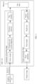
- FIG. 3 is a schematic flowchart of tile-based rendering of a GPU.
- a raster generator reads primitive tile data that belongs to a current tile from the GPU memory, and reads primitive vertex data from the memory.
- the primitive vertex data that belongs to the tile is used in the GPU rendering stage, to further generate an output image of the tile.
- the solution shown in FIG. 3 can avoid repeatedly executing a vertex shader in the rendering stage to generate the primitive vertex data, storing the primitive vertex data generated by the vertex shader increases a memory requirement of the GPU, and reading and writing the primitive vertex data usually increases bandwidth of the GPU. In particular, when memory and bandwidth resources of the GPU are limited, storing a large amount of primitive vertex data after geometry processing may affect overall performance of the GPU.
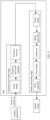
- FIG. 4 is another schematic flowchart of tile-based rendering of a GPU.
- a rendering stage the primitive obtained through geometry processing is processed by the vertex shader again, to regenerate coordinates of a primitive vertex on the screen.
- the regenerated primitive vertex data is used in a raster generator for rasterization processing, and is further used in the entire GPU rendering stage to generate an output image.
- the vertex shader needs to perform processing again, to re-generate the primitive vertex data.
- Repeated execution of the vertex shader in the rendering stage increases a computation amount of the GPU, and further affects rendering performance of the GPU.
- a simplified vertex shader may be executed to generate vertex position data required in the geometry processing stage, and in the rendering stage, the complete vertex shader is executed to generate all primitive vertex data. Even if this optimization measure is applied, impact of repeated execution of the vertex shader on the computation amount and the rendering performance of the GPU in a complex vertex shader computing scenario cannot be ignored.
- this application provides a graphics rendering method. Different rendering modes are selected, to reduce a requirement for both a memory and bandwidth of a GPU and a computation amount of a vertex shader. This improves overall performance of a tile-based rendering system of the GPU.
- Rendering is a stage in which an image finally conforms to a three-dimensional (three dimensions, 3D) scenario.
- rendering software such as rendering engines of various computer graphics (computer graphics, CG) software, and RenderMan.
- Rending is a process in architectural design, animation production, and the like, in which a model and an animation frame are created using software such as 3DS Max and Maya, and design content is used to produce a final effect drawing or animation using the software or auxiliary software (such as lightscape and vray).
- a tile-based rendering architecture rasterization is performed on each tile, which is a main difference from a conventional immediate rendering structure.
- each of all to-be-drawn primitives need to be temporarily stored in a system memory based on a tile in which the primitive is located.
- rendering may be performed tile by tile based on a tile sequence, and traditional read-modify-write operations for a color buffer, a depth buffer, and a template buffer can be performed on a small on-chip memory without repeated access to a system memory.
- content of an on-chip memory of the tile can be written to the memory at once (generally, only content of the color buffer need to be written back).
- This architecture can greatly reduce a quantity of access times, improve drawing efficiency, and reduce power consumption.
- Vertex shading is a rendering method.
- information such as a three-dimensional position, a color, and a direction of a vertex can be accessed. These values can be modified, or be transferred to a fragment shading stage, to implement specific rendering effect.
- the primitive is a basic graphical element.
- the basic graphical element is a basic graphic entity for constructing a complex geometrical graphic and frame. Different graphics systems have different graphic elements.
- the basic graphical element is a point, a line, a triangle, a mesh, and the like.
- a graphic displayed on a raster scan display is a set of pixels with one or more colors.
- a process of determining a set of pixels of a graphic of best approximation and writing pixels with a specified attribute is called scan conversion or generation of the graphic.
- the series of primitives in this application includes at least one primitive.
- FIG. 5 is a schematic flowchart of a graphics rendering method according to an embodiment of this application.
- the graphics rendering method is applied to a tile-based rendering system of a GPU (the system shown in FIG. 1 ).
- a rendering mode supported by the tile-based rendering system of the GPU includes a first rendering mode and a second rendering mode. It may be understood that the rendering mode supported by the tile-based rendering system of the GPU in this embodiment of this application is not a fixed specific rendering mode, and can support two different rendering modes for graphics rendering processing.
- the first rendering mode primitive vertex data generated by a series of primitives in a geometry processing stage that are input by a graphics application is stored in a GPU memory, the primitive vertex data is read from the memory to perform rendering in a raster processing stage, and an output image is generated (for example, the rendering manner shown in FIG. 3 ).
- the primitive vertex data generated by the series of primitives in the geometry processing stage that are input by the graphics application is not stored in the GPU memory, vertex shading processing is performed on the primitives obtained after the geometry processing stage in the raster processing stage to generate the primitive vertex data.
- the primitive vertex data is used for rendering to generate an output image (for example, the rendering manner shown in FIG. 4 ).
- the series of primitives only needs to be processed by a vertex shader in the geometry processing stage, and does not need to be processed by the vertex shader again in the raster processing stage.
- the second rendering mode after the series of primitives is processed by the vertex shader in the geometry processing stage, the series of primitives further needs to be processed by the vertex shader again in the raster processing stage.
- the first rendering mode may be referred to as a single execution mode
- the second rendering mode may be referred to as a repeated execution mode.
- first rendering mode and “second rendering mode”, or the “single execution mode” and the “repeated execution mode” are only intended to distinguish between different rendering modes supported by the tile-based rendering system of the GPU in this embodiment of this application, and do not constitute any limitation on the protection scope of this application.
- the rendering modes may be distinguished by using other names. Examples are not described herein again.
- a “storage mode” and a “non-storage mode” may also be used to distinguish between the rendering modes.
- a mode in which the primitive vertex data generated in the geometry processing stage is stored is referred to as the storage mode
- a mode in which the primitive vertex data generated in the geometry processing stage is not stored is referred to as the non-storage mode.
- the method includes the following steps.
- how the tile-based rendering system of the GPU receives the series of primitives input by the graphics application is not limited.
- the graphics application in this embodiment of this application may be the graphics application 110 shown in FIG. 1
- the series of primitives input by the graphics application may be some primitives in a to-be-rendered graphic in the graphics application 110.
- the graphics application may input primitives in the to-be-rendered graphic into the tile-based rendering system of the GPU in batches, and the tile-based rendering system of the GPU performs processing.
- a primitive that is input by the graphics application to the tile-based rendering system of the GPU each time is referred to as the series of primitives.
- the series of primitives in the following may also be referred to as primitive data, or referred to as a series of primitive input, or referred to as a primitive sequence, or the like.
- the tile-based rendering system of the GPU needs to perform rendering processing on the series of primitives, to produce a corresponding output picture.
- a method procedure shown in FIG. 5 further includes the following step:
- S520 Determine, based on a preset condition, to render the series of primitives by using the first rendering mode and/or the second rendering mode.
- the tile-based rendering system of the GPU when performing rendering, can determine, based on the preset condition, to use a more appropriate rendering mode to render the series of primitives, avoiding impact on GPU rendering performance by using a fixed rendering mode (for example, fixed use of the mode shown in FIG. 3 may increase a memory requirement of the GPU, and fixed use of the mode shown in FIG. 4 may increase a computation amount of the GPU).
- a fixed rendering mode for example, fixed use of the mode shown in FIG. 3 may increase a memory requirement of the GPU, and fixed use of the mode shown in FIG. 4 may increase a computation amount of the GPU.
- it may be determined, based on the preset condition, to render the series of primitives by using the first rendering mode.
- it may be determined, based on the preset condition, to render the series of primitives by using the second rendering mode.
- a rendering mode appropriate for a current series of primitives is selected from a plurality of rendering modes supported by the tile-based rendering system of the GPU. This improves overall performance of the tile-based rendering system of the GPU.
- the tile-based rendering system of the GPU can perform primitive rendering based on the determined rendering mode.
- the method procedure shown in FIG. 5 further includes the following step:
- S530 Render the series of primitives based on the first rendering mode and/or the second rendering mode.
- a specific process of performing rendering by the tile-based rendering system of the GPU is not limited in this embodiment of this application.
- the first rendering mode is determined for rendering, for a specific rendering process, refer to the rendering process shown in FIG. 3 .
- the second rendering mode is determined for rendering, refer to the rendering process shown in FIG. 4 .
- both the first rendering mode and the second rendering mode are determined for rendering, for a specific rendering process of a primitive using the first rendering mode, refer to the rendering process shown in FIG. 3
- for a specific rendering process of a primitive using the second rendering mode refer to the rendering process shown in FIG. 4 .
- the preset condition in this embodiment of this application includes at least one of the following: a proportionality constant is greater than a first threshold, a complexity weighting coefficient of a vertex shader program is greater than a second threshold, a primitive weighting coefficient is greater than a third threshold, a storage resource weighting coefficient is greater than a fourth threshold, or a comprehensive weighting coefficient is greater than a fifth threshold.
- preset condition is only examples of possible forms of the preset condition, and does not constitute any limitation on the protection scope of this application.
- Another preset condition may be further set to select the first rendering mode and/or the second rendering mode. For example, random selection is performed. For another example, a historical rendering record is used. Examples are not described herein again.
- the proportion constant is a ratio of a quantity of execution times of the first rendering mode to a quantity of execution times of the second rendering mode, and is denoted as Rc:
- Rc single_mode_count/repeat_mode_count.
- single _mode count indicates a quantity of execution times of a first rendering mode
- repeat_mode_count indicates a quantity of execution times of a second rendering mode.
- the first rendering mode similar to the rendering mode shown in FIG. 3 may be referred to as the single execution mode, and the second rendering mode similar to the rendering mode shown in FIG. 4 may be referred to as the repeated execution mode.
- That the proportion constant is greater than the first threshold indicates that the ratio of the quantity of execution times of the first rendering mode to the quantity of execution times of the second rendering mode is less than a specific preset threshold. For example, if the first threshold is less than 1, it indicates that the quantity of execution times of the first rendering mode is less than the quantity of execution times of the second rendering mode.
- the proportion constant when the proportion constant is greater than the first threshold, it is determined to use the first rendering mode.
- the proportion constant when the proportion constant is not greater than the first threshold, it is determined to use the second rendering mode, or use both the first rendering mode and the second rendering mode.
- the proportion constant when the proportion constant is greater than the first threshold, it is determined to use the second rendering mode.
- the proportion constant when the proportion constant is not greater than the first threshold, it is determined to use the first rendering mode, or use both the first rendering mode and the second rendering mode.
- the complexity weighting coefficient of the vertex shader program is a weighted value of the following parameters of the vertex shader program: a quantity of instructions, a quantity of complex instructions, a quantity of memory read instructions, and a quantity of executable loop instructions.
- a main weakness of the second rendering mode is that a quantity of executions of the vertex shader is increased, affecting GPU performance in the rendering process. Different weighting coefficients may be used to describe complexity of the vertex shader program, consequently determining whether to select the second rendering mode.
- the following factors may be considered as the complexity weighting coefficient of the following parameters of the vertex shader program: the quantity of instructions, the quantity of complex instructions (for example, log, and square root), the quantity of memory read instructions (for example, texture read), and the quantity of executable loop instructions.
- the weighting coefficients corresponding to the quantities of instructions may be determined and adjusted based on experimental data, to implement optimal effect.
- the complexity weighting coefficient of the vertex shader program when the complexity weighting coefficient of the vertex shader program is greater than the second threshold, it is determined to use the first rendering mode.
- the complexity weighting coefficient of the vertex shader program is not greater than the second threshold, it is determined to use the second rendering mode, or use both the first rendering mode and the second rendering mode.
- the complexity weighting coefficient of the vertex shader program when the complexity weighting coefficient of the vertex shader program is greater than the second threshold, it is determined to use the second rendering mode.
- the complexity weighting coefficient of the vertex shader program is not greater than the second threshold, it is determined to use the first rendering mode, or use both the first rendering mode and the second rendering mode.
- the foregoing weighting coefficient used to describe the complexity of the vertex shader program may be generated in a compilation process of the vertex shader.
- a rendering mode can be selected based on a feature of the vertex shader program.
- the first rendering mode should be usually used, that is, primitive vertex data generated in a geometry processing stage is stored in a GPU memory, and the primitive vertex data in the memory is read in a raster processing stage, reducing a workload of repeatedly executing a complex vertex shader program.
- the second rendering mode may be used, that is, a simple vertex shader program is repeatedly executed in the raster processing stage to regenerate the primitive vertex data.
- the primitive vertex data generated in the geometry processing stage does not need to be stored in the GPU memory, reducing requirements on both memory space and bandwidth of the GPU.
- this application provides another reference factor, namely, a ratio of a computation amount of the vertex shader to a computation amount of a pixel shader. Because a primitive on a screen usually includes a plurality of pixels, the computation amount of the pixel shader with a pixel as a granularity in the raster processing stage is much greater than the computation amount of the vertex shader with a primitive vertex as a granularity in the geometry processing stage.
- the computation amount of the vertex shader in the geometry processing stage may be greater than the computation amount of the pixel shader in the raster processing stage in the tile-based rendering system of the GPU.
- a pixel shader program may be extremely simple, while the vertex shader program may be relatively complex.
- the first rendering mode should not be selected, avoiding increasing a workload of the vertex shader.
- a simplified vertex shader program is executed to generate primitive vertex position data, which is used for geometry processing and tile-based processing of the primitive.
- the vertex shader program is re-executed to generate the primitive vertex data.
- the primitive weighting coefficient is a weighted value of primitive coverage and a quantity of bytes of the primitive vertex data.
- the primitive obtained after the geometry processing stage is distributed to the screen by a tiler.
- each tile covered by each primitive is separately processed on the screen. If the vertex shader is executed in the second rendering mode, in the rendering process of each tile, the vertex shader program is executed again on the primitive to generate the primitive vertex data. For primitives that cover a plurality of tiles on the screen, the vertex shader program may need to be repeatedly executed in a tile covered by each primitive. Repeated execution of the vertex shader program may further increase the workload of the vertex shader, affecting performance of the tile-based rendering system of the GPU.
- Another primitive feature that may affect rendering mode selection is a size of the primitive vertex data.
- the quantity of bytes of the primitive vertex data may range from 16 to 512 in the rendering process.
- the second rendering mode is appropriate for the series of primitives with the large quantity of bytes of the primitive vertex data.
- a primitive geometric weighting method proposed in this application uses a primitive geometric feature to help select a more optimized rendering mode.
- Tiles indicates a total quantity of tiles covered by a series of primitives on a screen; primitives indicates a total quantity of primitives in the series of primitives; vertices indicates a total quantity of primitive vertices of the series of primitives; vertex_size indicates a quantity of bytes of the primitive vertices of the series of primitives; and max_size indicates a maximum quantity of bytes of primitive vertex data, for example, 512 bytes.
- k1 and k2 are weighting coefficients corresponding to both primitive coverage and a quantity of bytes of the primitive vertex data.
- the weighting coefficients k1 and k2 may be determined and adjusted based on experimental data, to implement optimal effect.
- the primitive weighting coefficient when the primitive weighting coefficient is greater than the third threshold, it is determined to use the first rendering mode.
- the primitive weighting coefficient is not greater than the third threshold, it is determined to use the second rendering mode, or use both the first rendering mode and the second rendering mode.
- the primitive weighting coefficient when the primitive weighting coefficient is greater than the third threshold, it is determined to use the second rendering mode.
- the primitive weighting coefficient is not greater than the third threshold, it is determined to use the first rendering mode, or use both the first rendering mode and the second rendering mode.
- the foregoing primitive weighting coefficient Rg of the series of primitives may be used to select the rendering mode of the series of primitives.
- the first rendering mode should be used, that is, the primitive vertex data generated in the geometry processing stage is stored in the GPU memory, and the primitive vertex data in the memory is read in the raster processing stage.
- the first rendering mode is used. This reduces a workload of repeatedly executing the vertex shader program for a primitive with a high tile coverage rate. Storing vertex data with a small quantity of bytes of the primitive vertex data does not cause a large additional requirement on the memory space and bandwidth of the GPU.
- the second rendering mode may be used, that is, the vertex shader program is repeatedly executed in the raster processing stage to regenerate the primitive vertex data.
- the primitive vertex data generated in the geometry processing stage does not need to be stored in the GPU memory, avoiding an additional requirement on the memory space and bandwidth of the GPU caused by storing vertex data with a large quantity of bytes of the primitive vertex data.
- the vertex shader program is repeatedly executed for a primitive with a low tile coverage rate, an increased execution workload of the vertex shader is also controlled within an acceptable range.
- the storage resource weighting coefficient is greater than the fourth threshold.
- the storage resource weighting coefficient is storage resource utilization of the GPU memory.
- the vertex data generated by the vertex shader in the geometry processing stage is stored in the GPU memory for reading in the raster processing stage in the rendering process.
- the first rendering mode of the vertex shader may avoid repeatedly executing the vertex shader program in the raster processing stage to generate the primitive vertex data required in the rendering process, but this mode needs to occupy the storage space of the GPU memory.
- a storage resource of the GPU memory is usually limited. When the utilization of the GPU memory reaches a limit, the first rendering mode should not be selected as the rendering mode.
- the storage resource utilization of the GPU memory is used to help select a more optimized rendering mode.
- the storage resource weighting coefficient Rm is large, there is a plenty of available storage space in the GPU memory, and the first rendering mode may be selected as the rendering mode. If the storage resource weighting coefficient Rm is small, there is limited available storage space in the GPU memory, and the second rendering mode should be selected as the rendering mode.
- the storage resource weighting coefficient when the storage resource weighting coefficient is greater than the fourth threshold, it is determined to use the first rendering mode.
- the storage resource weighting coefficient when the storage resource weighting coefficient is not greater than the fourth threshold, it is determined to use the second rendering mode, or use both the first rendering mode and the second rendering mode.
- the comprehensive weighting coefficient is greater than the fifth threshold.
- the comprehensive weighting coefficient is a weighting value of the proportionality constant, the complexity weighting coefficient of the vertex shader program, the primitive weighting coefficient, and the storage resource weighting coefficient.
- Rs indicates a weighting coefficient of a vertex shader weighting method
- Rg indicates a weighting coefficient of a primitive geometric weighting method
- Rm indicates a weighting coefficient of a storage resource weighting method
- k1, k2, and k3 are weighting coefficients corresponding to weighting methods in the comprehensive weighting coefficient R.
- the weighting coefficients k1, k2, and k3 corresponding to the weighting methods may be determined and adjusted based on experimental data, to implement optimal effect.
- the first rendering mode of the vertex shader should be used, that is, the primitive vertex data generated in the geometry processing stage is stored in the GPU memory, and the primitive vertex data in the memory is read in the raster processing stage.
- the first rendering mode may reduce a workload of repeatedly executing a complex vertex shader program, and reduce a workload of repeatedly executing the vertex shader program for the primitive with the high screen tile coverage rate.
- the comprehensive weighting coefficient R is large, it also means that the GPU memory has a plenty of available storage space. Therefore, storage of the primitive vertex data is not affected.
- the second rendering mode of the vertex shader may be used, that is, the vertex shader program is repeatedly executed in the raster processing stage to regenerate the primitive vertex data.
- the primitive vertex data generated in the geometry processing stage does not need to be stored in the GPU memory, reducing requirements on both the memory space and bandwidth of the GPU.
- the comprehensive weighting coefficient R is small, it also means that the vertex shader program is of low complexity and a primitive tile coverage rate is low. Therefore, an additional workload caused by repeated execution of the vertex shader program does not affect performance of the tile-based rendering system of the GPU greatly.
- the comprehensive weighting coefficient when the comprehensive weighting coefficient is greater than the fifth threshold, it is determined to use the first rendering mode.
- the comprehensive weighting coefficient is not greater than the fifth threshold, it is determined to use the second rendering mode, or use both the first rendering mode and the second rendering mode.
- the rendering scenario is a preset rendering scenario.
- a rendering scenario of the graphics application may be used as a granularity to control rendering mode selection.
- the rendering mode is selected once in the rendering scenario by using the rendering scenario control method, which simplifies a control mode and greatly reduces a quantity of calculation times of the weighting coefficients (for example, the complexity weighting coefficient of the vertex shader program, the primitive weighting coefficient, and the storage resource weighting coefficient) and a change frequency of the rendering mode.
- the weighting coefficients for example, the complexity weighting coefficient of the vertex shader program, the primitive weighting coefficient, and the storage resource weighting coefficient
- the rendering scenario when the rendering scenario is a simple rendering scenario (for example, a screen post-processing scenario), it is determined to use the first rendering mode.
- the rendering scenario when the rendering scenario is a complex rendering scenario, it is determined to use the second rendering mode.
- Another solution for controlling rendering mode selection by using the rendering scenario control method is to predict rendering mode selection in a current rendering scenario by using a feature of the graphics application in a previous rendering scenario.
- predicting the rendering mode in the current rendering scenario by using the feature in the previous rendering scenario is a simple and effective solution.
- the preset condition in this application is briefly described in (1) to (6).
- the preset condition may be further determined in the following several manners: Manner 1: determining, based on the series of primitives input by the graphics application, that the preset condition includes at least one of the following: the complexity weighting coefficient of the vertex shader program is greater than the second threshold, the primitive weighting coefficient is greater than the third threshold, and the storage resource weighting coefficient is greater than the fourth threshold.
- the vertex shader program bound to the series of primitives is used to determine the complexity weighting coefficient of the vertex shader program.
- the primitive coverage and the quantity of bytes of the primitive vertex data in the series of primitives are used to determine the primitive weighting coefficient.
- the storage resource utilization of the GPU memory is used to determine the storage resource weighting coefficient.
- the rendering mode can be determined based on whether the preset condition is met.
- the vertex shader weighting coefficient for selecting the rendering mode may be calculated based on the vertex shader program bound to the series of primitives.
- the primitive geometric weighting coefficient for selecting the rendering mode may be calculated based on features of the primitive and the vertex data in the series of primitives.
- the storage resource weighting coefficient for selecting the rendering mode may be calculated. These weighting coefficients may be separately used to select an execution mode of the vertex shader in the series of primitives, or may be combined to select an execution mode of the vertex shader in the series of primitives.
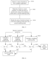
- FIG. 6 is a schematic flowchart of determining a rendering mode according to an embodiment of this application.
- a manner of determining the rendering mode includes the following steps:
- a vertex shader weighting coefficient Rs may be calculated based on the vertex shader program bound to the series of primitives.
- the primitive geometric weighting coefficient Rg may be calculated based on features of the primitive and vertex data in the series of primitives.
- the method procedure shown in FIG. 6 further includes: S623: Calculate a storage resource weighting coefficient Rm.
- the storage resource weighting coefficient Rm may be calculated for current GPU memory utilization.
- the determining a rendering mode based on a preset condition includes the following steps: S631: Determine whether a complexity weighting coefficient of the vertex shader program is greater than a second threshold (Ss).
- step S632 is performed.
- S632 Determine whether a primitive weighting coefficient is greater than the third threshold (Sg).
- step S633 is performed.
- S633 Determine whether the storage resource weighting coefficient is greater than a fourth threshold (Sm).
- the second rendering mode is selected; if the storage resource weighting coefficient Rm is not less than a specific constant Sm, the first rendering mode is selected.
- the vertex shader weighting coefficient Rs generated in a compilation process of the vertex shader program may be stored, to avoid repeated calculation of the vertex shader weighting coefficient when another series of primitives bound to the vertex shader program is processed.
- a feature of the vertex shader program, a geometric feature of the series of primitives, and a feature of GPU memory storage space are comprehensively considered. This is only used as an example for description, and does not constitute any limitation on the protection scope of this application.
- the rendering mode may further be selected in another manner. For example, without considering the feature of GPU memory storage space and/or the geometric feature of the series of primitives, if the vertex shader weighting coefficient Rs is less than the specific constant Ss, the second rendering mode is selected; if the vertex shader weighting coefficient Rs is not less than the specific constant Ss, the first rendering mode is selected. Examples are not provided for description herein one by one.
- Manner 2 determining, based on the vertex shader program input by the graphics application, that the preset condition includes that the complexity weighting coefficient of the vertex shader program is greater than the second threshold.
- the vertex shader program defined by the graphics application is used as a granularity to control selection of the rendering mode.
- the vertex shader weighting coefficient for selecting the rendering mode may be calculated based on compilation of the vertex shader program.
- a same vertex shader program may be bound to a plurality of series of primitives. Therefore, compared with the foregoing manner 1, the manner of selecting the rendering mode by using the vertex shader control method can make full use of a feature of the vertex shader program to select an appropriate rendering mode, reduce calculation of the weighting coefficients (for example, the foregoing primitive geometric weighting coefficient Rg and storage resource weighting coefficient Rm), and reduce a rendering mode change that may be caused (for example, a rendering mode change that is caused when each of the foregoing primitive geometric weighting coefficient Rg and storage resource weighting coefficient Rm does not meet a condition).
- the weighting coefficients for example, the foregoing primitive geometric weighting coefficient Rg and storage resource weighting coefficient Rm
- FIG. 7 is another schematic flowchart of determining a rendering mode according to an embodiment of this application.
- a manner of determining the rendering mode includes the following steps:
- a quantity of program instructions may be determined based on the program instructions.
- a parameter indicating a feature of the vertex shader program may be obtained, for example, a quantity of instructions, a quantity of complex instructions, a quantity of memory read instructions, and a quantity of loop instructions of the vertex shader program.
- a vertex shader weighting coefficient Rs is calculated based on the quantity of instructions.
- the method procedure shown in FIG. 7 further includes: S730: Calculate the vertex shader weighting coefficient Rs.
- the vertex shader program weighting coefficient Rs for selecting the rendering mode may be determined based on the foregoing vertex shader weighting method and the feature parameter of the vertex shader program.
- the determining a rendering mode based on a preset condition includes the following steps: S740: Determine whether a complexity weighting coefficient of the vertex shader program is greater than a second threshold (Ss).
- the second rendering mode is selected; if the vertex shader weighting coefficient Rs is not less than a specific constant Ss, the first rendering mode is selected.
- the execution mode is applied to rendering processes of all series of primitives bound to the vertex shader program.
- the embodiment shown in FIG. 7 can effectively utilize the features of the vertex shader program to select the rendering mode. This improves execution efficiency of the vertex shader and improves effective utilization of the GPU memory.
- the vertex shader may use a segmented output manner:
- the vertex shader may be compiled into two independent programs: one vertex shader program specially used to generate the primitive vertex position data, and the other vertex shader program used to generate the primitive vertex attribute data.
- the vertex shader in the geometry processing stage of the GPU, the vertex shader generates the primitive vertex data by executing the vertex shader program provided by the graphics application, including the vertex position data and attribute data, and further determines a shape and a position relationship of a three-dimensional graphic.
- the geometry processing stage in the tile-based rendering process of the GPU shown in FIG. 3 or FIG. 4 for a primitive on which vertex shader processing, and projection and screen mapping processing are performed, a primitive that is invisible on the screen is further removed through a primitive removal stage. Therefore, a total quantity of primitives finally output in the geometry processing stage is less than a quantity of primitives processed by the vertex shader.
- the position data is fixed, but an amount of vertex attribute data is not fixed.
- the amount of vertex attribute data is usually far greater than an amount of vertex position data.
- the primitive vertex position data and an extremely small amount of special primitive vertex attribute data related to primitive removal are required.
- the vertex shader program provided by the graphics application may be compiled into two independent vertex shader programs: one vertex shader program used to generate the primitive vertex position data, and the other vertex shader program used to generate the primitive vertex attribute data.
- both the quantity of instructions in the vertex shader program that generates the primitive vertex position data and amount of input and output data for executing the program usually reduce.
- the program is relatively simple. Therefore, this simplified vertex shader program is used in a rendering process in a stage requiring the primitive vertex position data. This can reduce a computation amount and improve performance of a GPU system.
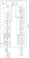
- FIG. 8 is a schematic block diagram of the GPU system according to an embodiment of this application.
- the primitive vertex position data is generated based on a first vertex shader in the geometry processing stage, where the primitive vertex position data is used to remove the primitive that is invisible on the screen; and primitive vertex attribute data corresponding to the primitive that is visible on the screen is generated based on a second vertex shader.
- a vertex shader #1 executes the vertex shader program that generates the primitive vertex position data.
- the primitive vertex position data generated by the vertex shader #1 is used in a subsequent process to remove the primitive that is invisible on the screen.
- a primitive that is not removed executes the vertex shader program that generates the primitive vertex attribute data by using a vertex shader #2, to generate the primitive vertex attribute data.
- the segmented output mode of the vertex shader may be applied to the first rendering mode, and the vertex shader program with a large computation amount that generates the primitive vertex attribute data is executed on a vertex of a primitive obtained after removal. This further reduces the computation amount of the vertex shader and improves the performance of the GPU system.
- a primitive in the first rendering mode, a primitive generates the primitive vertex data by using the vertex shader #1 and the vertex shader #2 shown in FIG. 8 in the geometry processing stage.
- the primitive vertex data is used by a tiler to distribute primitives into different tiles on the screen.
- the primitive vertex data is stored in the GPU memory.
- the primitive vertex data required for primitive rendering is read from the GPU memory, and therefore does not need to be processed by a vertex shader #3 and a vertex shader #4 (in the first mode, the vertex shader #3 and the vertex shader #4 may not exist).
- the vertex shader program may be compiled into a program for generating the vertex position data and a program for generating the vertex attribute data.
- the vertex shader #1 executes a simplified vertex shader program to generate the vertex position data, reducing the amount of computation.
- a primitive generates the vertex attribute data by using the vertex shader #2.
- the vertex shader program that generates the vertex attribute data needs to process the remaining primitive. Therefore, the computation amount of the vertex shader is further reduced, and the performance of the GPU system is improved.
- primitive vertex position data is generated based on a third vertex shader the raster processing stage, where the primitive vertex position data is used to remove a primitive that is invisible on a screen; and primitive vertex attribute data corresponding to a primitive that is visible on the screen is generated based on a fourth vertex shader.
- the vertex shader #3 in the raster processing stage in FIG. 8 executes a vertex shader program with a less computation amount that generates the primitive vertex position data.
- the primitive vertex position data generated by the vertex shader #3 is used to rasterize the primitive in a subsequent process and perform a depth test, to remove the primitive that is invisible on the screen.
- a depth test stage some blocked primitives are removed, and a primitive that is not removed executes the vertex shader program that generates the primitive vertex attribute data by using the vertex shader #4, to generate the primitive vertex attribute data required by the pixel shader in a subsequent process.
- the vertex shader program with a large computation amount that generates the primitive vertex attribute data is executed on a primitive vertex obtained after the depth test. This further reduces the computation amount of repeated execution of the vertex shader and improves the performance of the GPU system.
- the primitive in the second rendering mode, the primitive generates the primitive vertex data by executing the vertex shader #1 in FIG. 8 in the geometry processing stage.
- the primitive vertex data is used by the tiler to distribute primitives into different tiles on the screen.
- the primitive vertex data generated by using the vertex shader #1 is not stored in the GPU memory.
- the primitive vertex position data is required in the geometry processing stage. Therefore, in the second rendering mode, the vertex shader #1 needs only to execute the simplified vertex shader program to generate the vertex position data, and does not need to be processed by the vertex shader #2 (the vertex shader #2 may not exist in the first mode).
- the primitive vertex data required for primitive rendering is generated by the primitive through repeated execution of the vertex shader #3.
- the vertex shader program that generates the vertex attribute data may be postponed and executed in the vertex shader #4 after the depth test in the raster processing stage.
- the vertex shader #3 executes the simplified vertex shader program to generate the vertex position data, which is used in a raster generator and the depth test.
- this embodiment of this application mainly uses an example in which the rendering mode supported by the tile-based rendering system of the GPU includes the first rendering mode and the second rendering mode for description.
- the rendering mode supported by the tile-based rendering system of the GPU may alternatively be another rendering mode.
- the vertex position data generated by the vertex shader is stored in the GPU memory. Similar to the first rendering mode, in the tile-based rendering system shown in FIG. 8 , after screen projection and primitive removal, the vertex position data generated by the vertex shader #1 is used by the tiler to distribute primitives into different tiles on the screen. In addition, after primitive removal, the vertex position data is stored in the GPU memory.
- the vertex attribute data is not stored in GPU memory. Therefore, the vertex shader #2 is not required.
- the vertex position data stored in the GPU memory in the raster processing stage is read, and is used for raster generation and depth test processing of the primitive, without be processed by the vertex shader #3. After the depth test, the primitive generates the vertex attribute data required for rendering by using the vertex shader #4.
- this rendering mode reduces memory space and bandwidth for storing the vertex data.
- the second rendering mode reduces a workload of repeated execution of the vertex shader. In addition, because space required for storing the vertex position data is fixed, it is more convenient to manage GPU memory storage space.
- the rending mode is selected based on the preset condition for rendering, to avoid impact on GPU rendering performance caused by rendering based on a fixed mode.
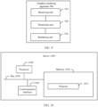
- FIG. 9 is a schematic block diagram of a graphics rendering apparatus 900 according to an embodiment of this application. It should be understood that the apparatus 900 can perform the steps in the methods in FIG. 5 to FIG. 8 . To avoid repetition, details are not described herein again.
- the graphics rendering apparatus 900 may be an electronic device, or the graphics rendering apparatus 900 may be a chip configured in an electronic device.
- the graphics rendering apparatus 900 includes: a receiving unit 910, a processing unit 920, and a rendering unit 930.
- the receiving unit 910 is configured to receive a series of primitives from a graphics application.
- the processing unit 920 is configured to determine, based on a preset condition, to perform graphics rendering and render the series of primitives by using the first rendering mode and/or the second rendering mode.
- the rendering unit 930 is configured to render the series of primitives based on the first rendering mode and/or the second rendering mode.
- the first rendering mode indicates to store, in a GPU memory, primitive vertex data generated by performing vertex shading processing on the series of primitives in a geometry processing stage, and read the primitive vertex data from the GPU memory in a raster processing stage to perform rendering processing.
- the second rendering mode indicates that the primitive vertex data generated by performing vertex shading processing on the series of primitives in the geometry processing stage is not stored in the GPU memory, vertex shading processing is performed on the series of primitives in the raster processing stage to generate the primitive vertex data, and rendering processing is performed on the primitive vertex data.
- the graphics rendering apparatus 900 herein is implemented in a form of a functional unit.
- the term "unit” herein may be implemented in a form of software and/or hardware. This is not specifically limited.
- the "unit” may be a software program, a hardware circuit, or a combination thereof for implementing the foregoing function.
- the hardware circuit may include an application-specific integrated circuit (application-specific integrated circuit, ASIC), an electronic circuit, a processor (for example, a shared processor, a dedicated processor, or a group processor) configured to execute one or more software or firmware programs, a memory, a merged logic circuit, and/or another appropriate component that supports the described function.
- ASIC application-specific integrated circuit
- the units in the example described in this embodiment of this application can be implemented by electronic hardware, or a combination of computer software and electronic hardware. Whether the functions are performed by hardware or software depends on particular applications and design constraint conditions of the technical solutions. A person skilled in the art may use different methods to implement the described functions for each particular application, but it should not be considered that the implementation goes beyond the scope of this application.
- FIG. 10 is a schematic block diagram of a server 1000 according to an embodiment of this application.
- the server 1000 includes a processor 1020, a memory 1030, a communication interface 1040, and a bus 1050.
- the processor 1020, the memory 1030, and the communication interface 1040 perform communication by using the bus 1050, or may implement communication through another means such as wireless transmission.
- the memory 1030 is configured to store instructions, and the processor 1020 is configured to execute the instructions stored in the memory 1030.
- the memory 1030 stores program code 1011, and the processor 1020 may invoke the program code 1011 stored in the memory 1030 to perform the graphics rendering method shown in FIG. 5 to FIG. 8 .
- the memory 1030 may include a read-only memory and a random access memory and provide an instruction and data to the processor 1020.
- the memory 1030 may further include a nonvolatile random access memory.
- the memory 1030 may be a volatile memory or a nonvolatile memory, or may include both a volatile memory and a nonvolatile memory.
- the nonvolatile memory may be a read-only memory (read-only memory, ROM), a programmable read-only memory (programmable ROM, PROM), an erasable programmable read-only memory (erasable PROM, EPROM), an electrically erasable programmable read-only memory (electrically EPROM, EEPROM), or a flash memory.
- the volatile memory may be a random access memory (random access memory, RAM), used as an external cache.
- RAM random access memory
- many forms of RAMs may be used, for example, a static random access memory (static RAM, SRAM), a dynamic random access memory (DRAM), a synchronous dynamic random access memory (synchronous DRAM, SDRAM), a double data rate synchronous dynamic random access memory (double data date SDRAM, DDR SDRAM), an enhanced synchronous dynamic random access memory (enhanced SDRAM, ESDRAM), a synchlink dynamic random access memory (synchlink DRAM, SLDRAM), and a direct rambus random access memory (direct rambus RAM, DR RAM).
- static random access memory static random access memory
- DRAM dynamic random access memory
- SDRAM synchronous dynamic random access memory
- double data rate synchronous dynamic random access memory double data date SDRAM, DDR SDRAM
- ESDRAM enhanced synchronous dynamic random access memory
- synchlink dynamic random access memory synchlink dynamic random access memory
- SLDRAM direct rambus
- the bus 1050 may further include a power bus, a control bus, a status signal bus, and the like. However, for clarity of description, various buses are marked as the bus 1050 in FIG. 10 .
- the processor 1020 may perform a step/function corresponding to the processing unit 920 shown in FIG. 9
- the communication interface 1040 may perform a step/function corresponding to the receiving unit 910 shown in FIG. 9 .
- the server 1000 shown in FIG. 10 can implement the processes performed by the devices in the method embodiments shown in FIG. 5 to FIG. 8 .
- Operations and/or functions of the modules in the server 1000 are intended to implement corresponding procedures of the devices in the foregoing method embodiments.
- a component may be, but is not limited to, a process that runs on a processor, a processor, an object, an executable file, an execution thread, a program, and/or a computer.
- a computing device and an application that runs on the computing device may be components.
- One or more components may reside in a process and/or an execution thread, and a component may be located on one computer and/or distributed between two or more computers.
- these components may be executed from various computer-readable media that store various data structures.
- the components may communicate by using a local and/or remote process based on a signal having one or more data packets (for example, data from two components interacting with another component in a local system, a distributed system, and/or across a network such as internet interacting with another system by using the signal).
- a signal having one or more data packets (for example, data from two components interacting with another component in a local system, a distributed system, and/or across a network such as internet interacting with another system by using the signal).
- the disclosed system, apparatus, and method can be performed in other manners.
- the described apparatus embodiment is only an example.
- division into the units is only logical function division and may be other division in actual implementation.
- a plurality of units or components may be combined or integrated into another system, or some features may be ignored or not performed.
- the displayed or discussed mutual couplings or direct couplings or communication connections may be implemented by using some interfaces.
- the indirect couplings or communication connections between the apparatuses or units may be implemented in electronic, mechanical, or other forms.
- the units described as separate parts may or may not be physically separate, and parts displayed as units may or may not be physical units, may be located in one position, or may be distributed on a plurality of network units. Some or all of the units may be selected based on actual requirements to implement the objectives of the solutions of embodiments.
- the functions When the functions are implemented in the form of a software functional unit and sold or used as an independent product, the functions may be stored in a computer-readable storage medium. Based on such an understanding, the technical solutions of this application essentially, or the part contributing to the conventional technology, or a part of the technical solutions may be implemented in a form of a software product.
- the computer software product is stored in a storage medium, and includes several instructions for indicating a computer device (which may be a personal computer, a server, a network device, or the like) to perform all or a part of the steps of the methods described in embodiments of this application.
- the foregoing storage medium includes any medium that can store program code, such as a USB flash drive, a removable hard disk, a read-only memory (Read-Only Memory, ROM), a random access memory (Random Access Memory, RAM), a magnetic disk, or an optical disc.
- program code such as a USB flash drive, a removable hard disk, a read-only memory (Read-Only Memory, ROM), a random access memory (Random Access Memory, RAM), a magnetic disk, or an optical disc.
Landscapes
- Engineering & Computer Science (AREA)
- Physics & Mathematics (AREA)
- General Physics & Mathematics (AREA)
- Theoretical Computer Science (AREA)
- Computer Graphics (AREA)
- Image Generation (AREA)
Applications Claiming Priority (1)
| Application Number | Priority Date | Filing Date | Title |
|---|---|---|---|
| PCT/CN2021/101386 WO2022266821A1 (zh) | 2021-06-22 | 2021-06-22 | 图形渲染的方法及装置 |
Publications (2)
| Publication Number | Publication Date |
|---|---|
| EP4354399A1 true EP4354399A1 (de) | 2024-04-17 |
| EP4354399A4 EP4354399A4 (de) | 2024-08-21 |
Family
ID=84543881
Family Applications (1)
| Application Number | Title | Priority Date | Filing Date |
|---|---|---|---|
| EP21946323.9A Pending EP4354399A4 (de) | 2021-06-22 | 2021-06-22 | Verfahren und vorrichtung zur grafikdarstellung |
Country Status (3)
| Country | Link |
|---|---|
| EP (1) | EP4354399A4 (de) |
| CN (1) | CN117501312A (de) |
| WO (1) | WO2022266821A1 (de) |
Families Citing this family (12)
| Publication number | Priority date | Publication date | Assignee | Title |
|---|---|---|---|---|
| CN116188241B (zh) * | 2023-01-18 | 2026-04-14 | 上海壁仞科技股份有限公司 | 图形处理器、操作方法和机器可读存储介质 |
| CN118429173A (zh) * | 2023-02-01 | 2024-08-02 | 华为技术有限公司 | 渲染方法、装置、电子设备以及计算机可读存储介质 |
| CN116843540B (zh) * | 2023-08-31 | 2024-01-23 | 南京砺算科技有限公司 | 图形处理器及图形处理设备 |
| CN117764808B (zh) * | 2023-12-22 | 2024-09-17 | 摩尔线程智能科技(北京)有限责任公司 | Gpu的数据处理方法、装置及存储介质 |
| CN117786913B (zh) * | 2024-01-09 | 2025-09-09 | 国网经济技术研究院有限公司 | 一种电网设备模型离散渲染方法、电子设备及存储介质 |
| CN117541744B (zh) * | 2024-01-10 | 2024-04-26 | 埃洛克航空科技(北京)有限公司 | 一种城市级实景三维图像的渲染方法及装置 |
| CN117745518B (zh) * | 2024-02-21 | 2024-06-11 | 芯动微电子科技(武汉)有限公司 | 一种优化内存分配的图形处理方法及系统 |
| WO2026000316A1 (zh) * | 2024-06-27 | 2026-01-02 | 荣耀终端股份有限公司 | 渲染处理方法及电子设备 |
| CN118887071B (zh) * | 2024-07-05 | 2025-10-14 | 摩尔线程智能科技(上海)有限责任公司 | Gpu图元预处理装置、系统及方法 |
| CN119919276B (zh) * | 2024-12-31 | 2025-07-04 | 摩尔线程智能科技(北京)股份有限公司 | 图元光栅化方法、装置、电子设备及存储介质 |
| CN121392104A (zh) * | 2025-10-21 | 2026-01-23 | 摩尔线程智能科技(北京)股份有限公司 | 渲染处理方法、装置、设备、存储介质及程序产品 |
| CN121437714A (zh) * | 2025-10-31 | 2026-01-30 | 摩尔线程智能科技(北京)股份有限公司 | 几何处理方法、系统、处理器、设备、介质及产品 |
Family Cites Families (9)
| Publication number | Priority date | Publication date | Assignee | Title |
|---|---|---|---|---|
| US7385609B1 (en) * | 2004-11-02 | 2008-06-10 | Nvidia Corporation | Apparatus, system, and method for increased processing flexibility of a graphic pipeline |
| US8031194B2 (en) * | 2007-11-09 | 2011-10-04 | Vivante Corporation | Intelligent configurable graphics bandwidth modulator |
| US9928565B2 (en) * | 2014-04-21 | 2018-03-27 | Qualcomm Incorporated | Flex rendering based on a render target in graphics processing |
| US20180082464A1 (en) * | 2016-09-16 | 2018-03-22 | Tomas G. Akenine-Moller | Apparatus and method for an efficient 3d graphics pipeline |
| US10403032B2 (en) * | 2017-08-22 | 2019-09-03 | Qualcomm Incorporated | Rendering an image from computer graphics using two rendering computing devices |
| CN109242756B (zh) * | 2018-09-07 | 2023-04-04 | 格兰菲智能科技有限公司 | 计算机系统、图形处理单元及其图形处理方法 |
| CN109325899B (zh) * | 2018-09-07 | 2023-04-04 | 格兰菲智能科技有限公司 | 计算机系统、图形处理单元及其图形处理方法 |
| US10733782B2 (en) * | 2018-10-05 | 2020-08-04 | Arm Limited | Graphics processing systems |
| CN112348929A (zh) * | 2020-11-26 | 2021-02-09 | 腾讯科技(深圳)有限公司 | 帧动画的渲染方法、装置、计算机设备及存储介质 |
-
2021
- 2021-06-22 EP EP21946323.9A patent/EP4354399A4/de active Pending
- 2021-06-22 WO PCT/CN2021/101386 patent/WO2022266821A1/zh not_active Ceased
- 2021-06-22 CN CN202180099453.2A patent/CN117501312A/zh active Pending
Also Published As
| Publication number | Publication date |
|---|---|
| WO2022266821A1 (zh) | 2022-12-29 |
| EP4354399A4 (de) | 2024-08-21 |
| CN117501312A (zh) | 2024-02-02 |
Similar Documents
| Publication | Publication Date | Title |
|---|---|---|
| EP4354399A1 (de) | Verfahren und vorrichtung zur grafikdarstellung | |
| TWI592902B (zh) | 來自片段著色器程式之樣本遮罩的控制 | |
| US11908039B2 (en) | Graphics rendering method and apparatus, and computer-readable storage medium | |
| US9355483B2 (en) | Variable fragment shading with surface recasting | |
| US9317960B2 (en) | Top-to bottom path rendering with opacity testing | |
| KR101286318B1 (ko) | 렌더링된 그래픽 엘리먼트들을 위한 성능 메트릭들의 시각적 표현의 디스플레이 | |
| US9230363B2 (en) | System, method, and computer program product for using compression with programmable sample locations | |
| US20140327690A1 (en) | System, method, and computer program product for computing indirect lighting in a cloud network | |
| US9230362B2 (en) | System, method, and computer program product for using compression with programmable sample locations | |
| US10055883B2 (en) | Frustum tests for sub-pixel shadows | |
| TW201435801A (zh) | 多重解析度一致性光柵化 | |
| US9558573B2 (en) | Optimizing triangle topology for path rendering | |
| US20140176529A1 (en) | Tile shader for screen space, a method of rendering and a graphics processing unit employing the tile shader | |
| US7928984B1 (en) | Efficient data packaging for rendering bézier curves on a GPU | |
| TW201428676A (zh) | 在上游著色器內設定下游著色狀態 | |
| EP4058973B1 (de) | Tessellierungsfaktoren mit reduzierter bandbreite | |
| JP2015515059A (ja) | シーンにおける不透明度レベルを推定する方法とそれに対応する装置 | |
| CN112001993A (zh) | 一种面向大场景的多gpu城市仿真系统 | |
| US20220036632A1 (en) | Post-processing in a memory-system efficient manner | |
| US10192348B2 (en) | Method and apparatus for processing texture | |
| CN106846452A (zh) | 一种gpu上针对延迟着色反走样绘制的优化方法 | |
| EP4229586B1 (de) | Optimierung eines gpu-kerns mit simo-ansatz zur abwärtsskalierung unter verwendung eines gpu-caches | |
| CN119816864A (zh) | 用于图形处理的快速msaa技术 | |
| CN116670719A (zh) | 一种图形处理方法、装置及电子设备 | |
| CN112581575A (zh) | 一种外视频做纹理系统 |
Legal Events
| Date | Code | Title | Description |
|---|---|---|---|
| STAA | Information on the status of an ep patent application or granted ep patent |
Free format text: STATUS: THE INTERNATIONAL PUBLICATION HAS BEEN MADE |
|
| PUAI | Public reference made under article 153(3) epc to a published international application that has entered the european phase |
Free format text: ORIGINAL CODE: 0009012 |
|
| STAA | Information on the status of an ep patent application or granted ep patent |
Free format text: STATUS: REQUEST FOR EXAMINATION WAS MADE |
|
| 17P | Request for examination filed |
Effective date: 20240110 |
|
| AK | Designated contracting states |
Kind code of ref document: A1 Designated state(s): AL AT BE BG CH CY CZ DE DK EE ES FI FR GB GR HR HU IE IS IT LI LT LU LV MC MK MT NL NO PL PT RO RS SE SI SK SM TR |
|
| REG | Reference to a national code |
Ref country code: DE Ref legal event code: R079 Free format text: PREVIOUS MAIN CLASS: G06T0015000000 Ipc: G06T0011400000 |
|
| A4 | Supplementary search report drawn up and despatched |
Effective date: 20240719 |
|
| RIC1 | Information provided on ipc code assigned before grant |
Ipc: G06T 15/00 20110101ALN20240715BHEP Ipc: G06T 11/40 20060101AFI20240715BHEP |
|
| DAV | Request for validation of the european patent (deleted) | ||
| DAX | Request for extension of the european patent (deleted) |