EP4354480A1 - Coupe-circuit cc - Google Patents
Coupe-circuit cc Download PDFInfo
- Publication number
- EP4354480A1 EP4354480A1 EP21945025.1A EP21945025A EP4354480A1 EP 4354480 A1 EP4354480 A1 EP 4354480A1 EP 21945025 A EP21945025 A EP 21945025A EP 4354480 A1 EP4354480 A1 EP 4354480A1
- Authority
- EP
- European Patent Office
- Prior art keywords
- fixed
- contact
- arc runner
- fixed contact
- side arc
- Prior art date
- Legal status (The legal status is an assumption and is not a legal conclusion. Google has not performed a legal analysis and makes no representation as to the accuracy of the status listed.)
- Pending
Links
Images


Classifications
-
- H—ELECTRICITY
- H01—ELECTRIC ELEMENTS
- H01H—ELECTRIC SWITCHES; RELAYS; SELECTORS; EMERGENCY PROTECTIVE DEVICES
- H01H73/00—Protective overload circuit-breaking switches in which excess current opens the contacts by automatic release of mechanical energy stored by previous operation of a hand reset mechanism
- H01H73/02—Details
- H01H73/18—Means for extinguishing or suppressing arc
-
- H—ELECTRICITY
- H01—ELECTRIC ELEMENTS
- H01H—ELECTRIC SWITCHES; RELAYS; SELECTORS; EMERGENCY PROTECTIVE DEVICES
- H01H9/00—Details of switching devices, not covered by groups H01H1/00 - H01H7/00
- H01H9/30—Means for extinguishing or preventing arc between current-carrying parts
- H01H9/46—Means for extinguishing or preventing arc between current-carrying parts using arcing horns
-
- H—ELECTRICITY
- H01—ELECTRIC ELEMENTS
- H01H—ELECTRIC SWITCHES; RELAYS; SELECTORS; EMERGENCY PROTECTIVE DEVICES
- H01H9/00—Details of switching devices, not covered by groups H01H1/00 - H01H7/00
- H01H9/30—Means for extinguishing or preventing arc between current-carrying parts
- H01H9/34—Stationary parts for restricting or subdividing the arc, e.g. barrier plate
- H01H9/346—Details concerning the arc formation chamber
-
- H—ELECTRICITY
- H01—ELECTRIC ELEMENTS
- H01H—ELECTRIC SWITCHES; RELAYS; SELECTORS; EMERGENCY PROTECTIVE DEVICES
- H01H9/00—Details of switching devices, not covered by groups H01H1/00 - H01H7/00
- H01H9/30—Means for extinguishing or preventing arc between current-carrying parts
- H01H9/34—Stationary parts for restricting or subdividing the arc, e.g. barrier plate
- H01H9/36—Metal parts
Definitions
- the present disclosure relates to a DC circuit breaker.
- a DC circuit breaker includes a fixed element having a fixed contact, a movable element having a movable contact contactable with and separable from the fixed element, arc runners for transferring an arc generated between contacts from the contacts, and an arc extinguishing chamber for extinguishing the arc, and the arc runners are respectively disposed near the fixed element and the movable element.
- an arc generated between the contacts upon contact separation at the time of current interruption is commutated from the contacts to the arc runners and travels on the arc runners, so as to be driven to the arc extinguishing chamber. Then, the arc enters grids inside the arc extinguishing chamber and is divided, so that an arc voltage not smaller than a power supply voltage of a DC circuit occurs, whereby the current is limited and interrupted.
- the DC circuit breaker quickly commutates an arc generated between contacts to the arc runners and drives the arc to the arc extinguishing chamber, whereby the life of the contacts can be prolonged by a shortened interruption time and a reduced wear amount of the contacts. Therefore, a configuration in which a protrusion is provided at a fixed-side arc runner to promptly commutate a generated arc from contacts to arc runners, is known (e.g., see Patent Document 1).
- Patent Document 1 Japanese Laid-Open Patent Publication No. 2010-170876
- an effect can be expected in a small current region not larger than rated current, in which it is difficult to commutate an arc from the contacts to the arc runners.
- an effect that commutation time is shortened according to the shape of a commutation destination is small in a large current region not smaller than rated current, in which the arc diameter is large and driving force is great. Therefore, it is difficult to improve commutation and traveling performance over the entire region from the small current region to the large current region by using the shape of an arc runner.
- the present disclosure has been made to solve the above problem, and an object of the present disclosure is to provide a DC circuit breaker including an arc runner capable of obtaining high interruption performance by shortening commutation time.
- a DC circuit breaker includes a fixed element having a fixed contact, a movable element having a movable contact contactable with and separable from the fixed contact, and a fixed-side arc runner that is disposed near the fixed contact and the movable contact and that drives an arc generated at the time of opening of the fixed contact and the movable contact to an arc extinguishing chamber.
- the fixed contact has an end surface connected to the fixed-side arc runner and side surfaces adjacent to the end surface, and the fixed-side arc runner is formed so as to cover the end surface and the side surfaces of the fixed contact.
- a biased magnetic flux occurs around the generated arc, whereby driving force toward a fixed-side arc runner is increased and commutation time is shortened, thereby obtaining high interruption performance.
- FIG. 1 is a schematic sectional view of the entire configuration of the DC circuit breaker of embodiment 1
- FIG. 2 is a sectional view illustrating movement of an arc in an interruption process of the DC circuit breaker
- FIG. 3 is a perspective view of a fixed element and a fixed-side arc runner of the DC circuit breaker
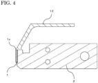
- FIG. 4 is a sectional view along line A-A in FIG. 3 .
- the DC circuit breaker includes a fixed element 3 composed of a fixed contact 1 and a fixed contact base metal 2, and a movable element 6 composed of a movable contact 4 and a movable contact base metal 5 contactable with and separable from the fixed contact 1.
- a closing actuator 7 When current is conducted, the movable element 6 is moved toward a fixed element by a closing actuator 7 so as to contact with the fixed element 3, whereby current is conducted via an upper conductor 8 connected to the fixed element 3 and a lower conductor 9 connected to the movable element 6.
- a detector 10 disposed on the lower conductor 9 detects the failure current and is operated, and releases a latch 11 having held the movable element 6, whereby the movable element 6 is separated from the fixed element 3 to perform an opening operation.
- an arc 16 shown in FIG. 2 is generated (hereinafter referred to as arcing) between the fixed contact 1 and the movable contact 4.
- the arc 16 generated between the contacts is transferred (hereinafter referred to as commutated) to a fixed-side arc runner 12 disposed near the fixed element 3 (fixed contact 1) and a movable-side arc runner 13 disposed near the movable element 6 (movable contact 4).
- the arc 17 generated between the fixed-side arc runner 12 and the movable-side arc runner 13 travels in a direction away from the contacts by an electromagnetic force due to current flowing on each arc runner or a flow of a conductive hot gas generated in arcing or the like.
- the arc 18 enters an arc extinguishing chamber 15 in which many grids 14 each formed of a thin-plate-shaped magnetic material are arranged, and the arc 19 is divided by the grids 14, so that an arc voltage is increased and becomes a power supply voltage of the circuit or higher, whereby the current is limited and interrupted.
- the arc 16 generated by separation of the movable contact 4 is commutated to the fixed-side arc runner 12, travels in a direction opposite to the contacts, and then enters the grids 14 so as to be interrupted.
- FIG. 3 and FIG. 4 the configuration of the fixed-side arc runner 12 will be described.
- components other than the fixed-side arc runner 12 and the fixed element 3 are omitted.
- appearance of each arc only on the fixed side is shown.
- the fixed contact 1 made of a silver alloy, the fixed contact base metal 2 made of copper, and the fixed-side arc runner 12 made of iron are brazed and configured so as to be in contact with each other.
- the fixed contact 1 has an end surface 1a (hereinafter, referred to as upper surface) that is connected to the fixed-side arc runner 12, and side surfaces 1b adjacent to the upper surface 1a.
- the side surfaces 1b of the fixed contact 1 are opposed to the fixed-side arc runner 12, and the fixed-side arc runner 12 is formed so as to cover the upper surface 1a and the side surfaces 1b of the fixed contact 1.
- the fixed-side arc runner 12 as a magnetic material is formed in a range including a portion around the fixed contact 1, whereby not only the electromagnetic force due to the self-magnetic field but also a biased magnetic flux can occur. More specifically, the fixed-side arc runner 12 is formed in a shape covering from the upper part of the fixed contact 1 to the side surfaces 1b of the fixed contact 1, that is, the fixed-side arc runner 12 covers in a U shape from the upper part of the fixed contact 1, whereby the biased magnetic flux is used.
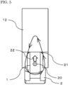
- FIG. 5 is a view of the fixed-side arc runner 12 when seen from an abutting surface side of the fixed contact 1.
- the current due to the arc 16 generated between the fixed contact 1 and the movable contact 4 flows toward a frontward direction 20 of the drawing sheet, and a magnetic flux 21 occurs in a right-hand screw direction with respect to the current.
- a magnetic material fixed-side arc runner 12
- the magnetic flux passes in the magnetic material having high magnetic permeability, and the magnetic flux that is originally concentric with current is biased.
- an electromagnetic force 22 toward the fixed-side arc runner 12 occurs in the arc through which current flows, and the arc is quickly elongated, thereby shortening commutation time.
- Such a shape that the side surfaces 1b of the fixed contact 1 are covered by the fixed-side arc runner 12 corresponds to a configuration for generating larger bias in a magnetic flux and increasing an electromagnetic force.
- the fixed-side arc runner 12 only has to cover at least a part of the side surfaces 1b of the fixed contact 1.
- the magnetic flux positioned lower than an arcing position also passes the fixed-side arc runner 12, so that the electromagnetic force toward the fixed-side arc runner 12 decreases.
- the length of the side surface portions of the fixed-side arc runner 12 covering the fixed contact 1 preferably extends to a contact intermediate position substantially corresponding to the arcing position.
- the upper part (upper surface 1a) of the fixed contact 1 is brazed so as to be in contact with the fixed-side arc runner 12.
- the arc generated between the contacts is commutated to the fixed-side arc runner 12.
- commutation is not smoothly performed, so that interruption performance may decrease or failure of interruption may be caused.
- the upper part of the fixed contact 1 and the fixed-side arc runner 12 are in contact with each other, thereby promoting commutation.
- the contact-direction height of the fixed-side arc runner 12 at the side surface portions of the fixed contact 1 is preferably the same as that of a contact abutting surface or lower than the contact abutting surface. If the fixed-side arc runner 12 at the side surface portions of the fixed contact 1 is made higher than the contact abutting surface and disposed nearer the movable contact 4 than the fixed contact 1, an opening distance between the movable element 6 and the fixed element 3 is shorter than the distance between the contacts, so that withstand voltage performance may be deteriorated, and the movable contact 4 may come into contact with the fixed-side arc runner 12 at the time of closing and thus conduction fault may be caused.
- the height of the contact abutting surface (surface to separate/contact from/to movable contact 4) of the fixed contact 1 means a height from a lower surface (surface opposite to the contact abutting surface) of the fixed contact 1.
- a plane including the lower surface of the fixed contact 1 is defined as a reference plane
- the height of portions, which respectively cover the side surfaces 1b of the fixed contact 1, of the fixed-side arc runner 12 means a height in a contact direction (the left direction in FIG. 4 ) from the reference surface.
- the end surface (upper surface) and the side surfaces adjacent to the upper surface of the fixed contact 1 are covered with the fixed-side arc runner 12, and the upper part of the fixed contact 1 and the fixed-side arc runner 12 are connected with each other. Accordingly, the biased magnetic flux occurs with respect to the generated arc and thus an electromagnetic force toward the fixed-side arc runner 12 is increased and a driving force is increased, whereby commutation time is shortened, so that high interruption performance can be obtained.
- the fixed-side arc runner 12 does not cover a back surface of the fixed contact 1 in embodiment 1, but a fixed-side arc runner 12 has a shape covering not only side surfaces but also a contact back surface of a fixed contact 1 in embodiment 2.
- the configuration of a DC circuit breaker of embodiment 2 is the same as that of embodiment 1 except that the fixed-side arc runner 12 covers the contact back surface.
- FIG. 6 is a sectional view showing the fixed-side arc runner of embodiment 2. As shown in FIG. 6 , the fixed-side arc runner 12 also covers the contact back surface, and thus a high effect of improving an electromagnetic force is obtained.
- the arc runner covering the contact back surface is disposed in such a position as not to be in contact with the arc, and thus the part covering the contact back surface and the fixed-side arc runner 12 may be formed as separate members.
- a slit 23 is provided in the fixed contact base metal 2. In the configuration, an electromagnetic force due to the self-magnetic field is increased.
- the configuration of a DC circuit breaker in embodiment 3 is the same as those of embodiments 1 and 2 except that the slit 23 is provided.
- FIG. 7 is a sectional view of the fixed-side arc runner 12 of the present embodiment when seen from a side surface thereof.
- the slit 23 is formed rearward of a contact back surface of the fixed contact base metal 2 so as to be parallel to the abutting surface of the fixed contact 1.
- FIG. 7 an example in which the slit 23 is formed in the fixed-side arc runner 12 of embodiment 2 is shown, but the slit may be formed in the fixed-side arc runner 12 of embodiment 1.
- the slit 23 is formed in a portion (an upper surface of the fixed contact base metal 2 in FIG. 7 ), on the fixed-side arc runner 12 side in the fixed contact base metal 2, whereby a path 24 is formed such that a current path thereof near the fixed contact 1 circumvents the slit 23 and advances from below, and by the magnetic flux that occurs from the path 24, an electromagnetic force 25 toward the fixed-side arc runner 12 acts on the arc 16 generated between the contacts. Accordingly, elongation of the arc is promoted and commutation time can be shortened.
- the slit 23 provided in the fixed contact base metal 2 approaches the abutting surface of the fixed contact 1.
- a higher effect is obtained, when the slit 23 is formed deeper so as to reach the vicinity of a lower part of the fixed contact base metal 2. It is effective and preferable that the slit 23 has such an angle as to be parallel to the abutting surface of the fixed contact 1. However, even if the above angle is changed to a predetermined angle other than the above angle, a similar effect is obtained.
- a position where the slit 23 is provided may be determined, in consideration of mechanical strength that can withstand contact opening/closing and a limit value of temperature increase due to energization, and the slit 23 may be provided in a different position for another configuration having a different rated value or the like.
- a part of the fixed-side arc runner 12 as described in embodiments 1 and 2 may be disposed rearward of the slit 23 to ensure the strength.
- Such a configuration increases not only strength, but also an effect caused by the electromagnetic force when a deep slit is provided.
- the slit 23 is partially closed with the fixed-side arc runner 12, and thus a current path flowing from above to the contact direction via the fixed-side arc runner 12 occurs.
- a difference between conductivity of copper, which is a material of the fixed contact base metal 2 and conductivity of iron, which is a material of the fixed-side arc runner 12 allows lower-path current passing through copper to be dominant, and thus strength is ensured without significantly reducing the electromagnetic force.
- FIG. 8 is a perspective view of the fixed element and the fixed-side arc runner of the present embodiment. As shown in FIG. 8 , the ribs 26 continuing from the vicinity of the contact to the end of the fixed-side arc runner 12 are respectively erected on the side surfaces of the fixed-side arc runner 12.
- the present configuration promotes commutation and traveling of an arc, in small current that is not larger than a rated current value and that has a weak arc driving force.
- the configuration of a DC circuit breaker in embodiment 4 is the same as those in embodiments 1 to 3 except that the ribs 26 are provided.
- the ribs 26 are respectively erected on the side surfaces of the fixed-side arc runner 12, and furthermore, the ribs 26 are provided so as to continue to the end of the fixed-side arc runner 12, whereby commutation performance and traveling performance are improved and elongation of an arc is promoted, so that a high arc voltage can be obtained, thereby improving interruption performance for small current.
- the DC circuit breaker of the present embodiment leads to reduction in size and weight thereof, compared to the DC circuit breaker using the air puffer.
- each rib 26 and the fixed-side arc runner 12 are integrally formed through cutting processing, but may be produced as different members and may be fastened by a bolt, a rivet, or the like or welded to each other.
- the rib 26 may be formed through not only cutting processing but also sheet metal bending processing.
- the fixed-side arc runner 12 and each rib 26 of the side surface thereof are formed as separate members, a portion (e.g., a screwing portion in a case where they are fixed by screwing) where they are connected and the other portion have different contact degrees. Since current flows concentratedly through the connection portion having a high contact degree, current having flowed through the connection portion may apply an electromagnetic force in a contact direction to an arc, depending on a position where the connection portion is formed, so that the arc flows backward toward the contact side in some cases. In contrast, when the ribs 26 and the fixed-side arc runner 12 are integrally formed, current does not flow concentratedly through the connection positions, and the arc driving force only toward the arc extinguishing chamber 15 can be obtained. Thus, the ribs 26 on the side surfaces of the fixed-side arc runner 12 are preferably formed integrally with the fixed-side arc runner 12.
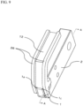
- FIG. 9 is a perspective view of the fixed element and the fixed-side arc runner of the present embodiment
- FIG. 10 is a sectional view of the fixed element and the fixed-side arc runner along line A-A in FIG. 9 .
- the configuration of a DC circuit breaker of embodiment 5 is the same as that of embodiment 4 except that the fixed-side arc runner 12, the fixed contact 1, and the fixed contact base metal 2 are integrated.
- the fixed contact 1, the fixed contact base metal 2, and the fixed-side arc runner 12 are integrally brazed, and then a cutting processing 27 is performed on a portion from an upper end surface of the fixed contact 1 to the fixed-side arc runner 12, whereby a boundary between the upper end surface of the fixed contact 1 and the fixed-side arc runner 12 is formed to be smoothly continuous.
- a generated small current arc is prevented from being stagnant and staying at the boundary that is a joint between the fixed contact 1 and the fixed-side arc runner 12 and that is formed after brazing, commutation to the fixed-side arc runner 12 is promoted, and interruption performance can be improved.
Landscapes
- Breakers (AREA)
- Arc-Extinguishing Devices That Are Switches (AREA)
Applications Claiming Priority (1)
| Application Number | Priority Date | Filing Date | Title |
|---|---|---|---|
| PCT/JP2021/021668 WO2022259347A1 (fr) | 2021-06-08 | 2021-06-08 | Coupe-circuit cc |
Publications (2)
| Publication Number | Publication Date |
|---|---|
| EP4354480A1 true EP4354480A1 (fr) | 2024-04-17 |
| EP4354480A4 EP4354480A4 (fr) | 2024-07-31 |
Family
ID=81215071
Family Applications (1)
| Application Number | Title | Priority Date | Filing Date |
|---|---|---|---|
| EP21945025.1A Pending EP4354480A4 (fr) | 2021-06-08 | 2021-06-08 | Coupe-circuit cc |
Country Status (3)
| Country | Link |
|---|---|
| EP (1) | EP4354480A4 (fr) |
| JP (1) | JP7031083B1 (fr) |
| WO (1) | WO2022259347A1 (fr) |
Family Cites Families (11)
| Publication number | Priority date | Publication date | Assignee | Title |
|---|---|---|---|---|
| JPS57163618U (fr) * | 1981-04-08 | 1982-10-15 | ||
| KR860002080B1 (ko) * | 1982-01-28 | 1986-11-24 | 카다야마히도 하지로 | 전력 개폐장치 |
| JPS6132325A (ja) * | 1984-07-24 | 1986-02-15 | 三菱電機株式会社 | 回路しや断器 |
| JPH0446331Y2 (fr) * | 1986-02-26 | 1992-10-30 | ||
| JP3252661B2 (ja) * | 1995-07-05 | 2002-02-04 | 富士電機株式会社 | 回路しゃ断器 |
| JP3955702B2 (ja) * | 1999-12-03 | 2007-08-08 | 三菱電機株式会社 | 回路遮断器 |
| US6300586B1 (en) * | 1999-12-09 | 2001-10-09 | General Electric Company | Arc runner retaining feature |
| JP2010170876A (ja) * | 2009-01-23 | 2010-08-05 | Mitsubishi Electric Corp | 回路遮断器 |
| US9029727B2 (en) * | 2013-01-24 | 2015-05-12 | Eaton Corporation | Arc runners suitable for DC molded case circuit breakers and related methods |
| JP6007135B2 (ja) * | 2013-03-07 | 2016-10-12 | 株式会社日立産機システム | 回路遮断器 |
| JP6336848B2 (ja) * | 2014-07-31 | 2018-06-06 | 河村電器産業株式会社 | 直流遮断器 |
-
2021
- 2021-06-08 WO PCT/JP2021/021668 patent/WO2022259347A1/fr not_active Ceased
- 2021-06-08 EP EP21945025.1A patent/EP4354480A4/fr active Pending
- 2021-06-08 JP JP2021564251A patent/JP7031083B1/ja active Active
Also Published As
| Publication number | Publication date |
|---|---|
| JP7031083B1 (ja) | 2022-03-07 |
| JPWO2022259347A1 (fr) | 2022-12-15 |
| WO2022259347A1 (fr) | 2022-12-15 |
| EP4354480A4 (fr) | 2024-07-31 |
Similar Documents
| Publication | Publication Date | Title |
|---|---|---|
| EP2980821B1 (fr) | Appareillage de commutation | |
| EP3447782B1 (fr) | Dispositif de contacteur pour disjoncteur et disjoncteur utilisant ce dispositif contacteur | |
| JP6516078B1 (ja) | 回路遮断器及び回路遮断方法 | |
| JP4493859B2 (ja) | 回路遮断器用の極 | |
| JP6203428B2 (ja) | 直流高速度遮断器 | |
| CN108140499B (zh) | 开关设备 | |
| CN1841615B (zh) | 单块固定导体和包含该导体的电力开关 | |
| CN107204263B (zh) | 用于高安培数多指断路器的槽式马达构造 | |
| US7148774B1 (en) | Contact assembly | |
| EP4354480A1 (fr) | Coupe-circuit cc | |
| KR100744245B1 (ko) | 배선용 회로 차단기 | |
| HK40105904A (en) | Dc circuit breaker | |
| KR100386629B1 (ko) | 회로차단기의 소호장치 | |
| JP2013140767A (ja) | 開閉器 | |
| JP2004273235A (ja) | 回路遮断器 | |
| JP2013164920A (ja) | 回路遮断器 | |
| JP2010170787A (ja) | 回路遮断器 | |
| EP0124620A1 (fr) | Commutateur | |
| JP2021125368A (ja) | アークランナーおよびこれを用いた回路遮断器 | |
| JP3407102B2 (ja) | 回路遮断器 | |
| JP7149754B2 (ja) | 回路遮断器 | |
| JPH0620550A (ja) | 開閉器 | |
| JP7040103B2 (ja) | 回路遮断器 | |
| JP3645774B2 (ja) | 限流形遮断装置 | |
| JPH0221090B2 (fr) |
Legal Events
| Date | Code | Title | Description |
|---|---|---|---|
| STAA | Information on the status of an ep patent application or granted ep patent |
Free format text: STATUS: THE INTERNATIONAL PUBLICATION HAS BEEN MADE |
|
| PUAI | Public reference made under article 153(3) epc to a published international application that has entered the european phase |
Free format text: ORIGINAL CODE: 0009012 |
|
| STAA | Information on the status of an ep patent application or granted ep patent |
Free format text: STATUS: REQUEST FOR EXAMINATION WAS MADE |
|
| 17P | Request for examination filed |
Effective date: 20230928 |
|
| AK | Designated contracting states |
Kind code of ref document: A1 Designated state(s): AL AT BE BG CH CY CZ DE DK EE ES FI FR GB GR HR HU IE IS IT LI LT LU LV MC MK MT NL NO PL PT RO RS SE SI SK SM TR |
|
| REG | Reference to a national code |
Ref country code: DE Ref legal event code: R079 Free format text: PREVIOUS MAIN CLASS: H01H0009380000 Ipc: H01H0009460000 |
|
| A4 | Supplementary search report drawn up and despatched |
Effective date: 20240703 |
|
| RIC1 | Information provided on ipc code assigned before grant |
Ipc: H01H 9/36 20060101ALN20240627BHEP Ipc: H01H 9/34 20060101ALN20240627BHEP Ipc: H01H 73/18 20060101ALI20240627BHEP Ipc: H01H 9/46 20060101AFI20240627BHEP |
|
| REG | Reference to a national code |
Ref country code: HK Ref legal event code: DE Ref document number: 40105904 Country of ref document: HK |
|
| DAV | Request for validation of the european patent (deleted) | ||
| DAX | Request for extension of the european patent (deleted) | ||
| GRAP | Despatch of communication of intention to grant a patent |
Free format text: ORIGINAL CODE: EPIDOSNIGR1 |
|
| STAA | Information on the status of an ep patent application or granted ep patent |
Free format text: STATUS: GRANT OF PATENT IS INTENDED |
|
| RIC1 | Information provided on ipc code assigned before grant |
Ipc: H01H 9/46 20060101AFI20251215BHEP Ipc: H01H 73/18 20060101ALI20251215BHEP Ipc: H01H 9/34 20060101ALN20251215BHEP Ipc: H01H 9/36 20060101ALN20251215BHEP |
|
| INTG | Intention to grant announced |
Effective date: 20260107 |
|
| GRAJ | Information related to disapproval of communication of intention to grant by the applicant or resumption of examination proceedings by the epo deleted |
Free format text: ORIGINAL CODE: EPIDOSDIGR1 |
|
| STAA | Information on the status of an ep patent application or granted ep patent |
Free format text: STATUS: REQUEST FOR EXAMINATION WAS MADE |
|
| GRAP | Despatch of communication of intention to grant a patent |
Free format text: ORIGINAL CODE: EPIDOSNIGR1 |
|
| STAA | Information on the status of an ep patent application or granted ep patent |
Free format text: STATUS: GRANT OF PATENT IS INTENDED |
|
| INTG | Intention to grant announced |
Effective date: 20260310 |
|
| RIC1 | Information provided on ipc code assigned before grant |
Ipc: H01H 9/46 20060101AFI20260302BHEP Ipc: H01H 73/18 20060101ALI20260302BHEP Ipc: H01H 9/34 20060101ALN20260302BHEP Ipc: H01H 9/36 20060101ALN20260302BHEP |