EP4354585A1 - Wasserdichte anordnung für energiespeichervorrichtung und energiespeichervorrichtung - Google Patents
Wasserdichte anordnung für energiespeichervorrichtung und energiespeichervorrichtung Download PDFInfo
- Publication number
- EP4354585A1 EP4354585A1 EP22897568.6A EP22897568A EP4354585A1 EP 4354585 A1 EP4354585 A1 EP 4354585A1 EP 22897568 A EP22897568 A EP 22897568A EP 4354585 A1 EP4354585 A1 EP 4354585A1
- Authority
- EP
- European Patent Office
- Prior art keywords
- wire harness
- outward protruding
- protruding portion
- recess
- boss
- Prior art date
- Legal status (The legal status is an assumption and is not a legal conclusion. Google has not performed a legal analysis and makes no representation as to the accuracy of the status listed.)
- Granted
Links
Images


Classifications
-
- H—ELECTRICITY
- H01—ELECTRIC ELEMENTS
- H01M—PROCESSES OR MEANS, e.g. BATTERIES, FOR THE DIRECT CONVERSION OF CHEMICAL ENERGY INTO ELECTRICAL ENERGY
- H01M50/00—Constructional details or processes of manufacture of the non-active parts of electrochemical cells other than fuel cells, e.g. hybrid cells
- H01M50/20—Mountings; Secondary casings or frames; Racks, modules or packs; Suspension devices; Shock absorbers; Transport or carrying devices; Holders
- H01M50/233—Mountings; Secondary casings or frames; Racks, modules or packs; Suspension devices; Shock absorbers; Transport or carrying devices; Holders characterised by physical properties of casings or racks, e.g. dimensions
- H01M50/24—Mountings; Secondary casings or frames; Racks, modules or packs; Suspension devices; Shock absorbers; Transport or carrying devices; Holders characterised by physical properties of casings or racks, e.g. dimensions adapted for protecting batteries from their environment, e.g. from corrosion
-
- H—ELECTRICITY
- H01—ELECTRIC ELEMENTS
- H01M—PROCESSES OR MEANS, e.g. BATTERIES, FOR THE DIRECT CONVERSION OF CHEMICAL ENERGY INTO ELECTRICAL ENERGY
- H01M10/00—Secondary cells; Manufacture thereof
- H01M10/42—Methods or arrangements for servicing or maintenance of secondary cells or secondary half-cells
-
- H—ELECTRICITY
- H01—ELECTRIC ELEMENTS
- H01M—PROCESSES OR MEANS, e.g. BATTERIES, FOR THE DIRECT CONVERSION OF CHEMICAL ENERGY INTO ELECTRICAL ENERGY
- H01M50/00—Constructional details or processes of manufacture of the non-active parts of electrochemical cells other than fuel cells, e.g. hybrid cells
- H01M50/20—Mountings; Secondary casings or frames; Racks, modules or packs; Suspension devices; Shock absorbers; Transport or carrying devices; Holders
- H01M50/204—Racks, modules or packs for multiple batteries or multiple cells
- H01M50/207—Racks, modules or packs for multiple batteries or multiple cells characterised by their shape
- H01M50/209—Racks, modules or packs for multiple batteries or multiple cells characterised by their shape adapted for prismatic or rectangular cells
-
- H—ELECTRICITY
- H01—ELECTRIC ELEMENTS
- H01M—PROCESSES OR MEANS, e.g. BATTERIES, FOR THE DIRECT CONVERSION OF CHEMICAL ENERGY INTO ELECTRICAL ENERGY
- H01M50/00—Constructional details or processes of manufacture of the non-active parts of electrochemical cells other than fuel cells, e.g. hybrid cells
- H01M50/20—Mountings; Secondary casings or frames; Racks, modules or packs; Suspension devices; Shock absorbers; Transport or carrying devices; Holders
- H01M50/298—Mountings; Secondary casings or frames; Racks, modules or packs; Suspension devices; Shock absorbers; Transport or carrying devices; Holders characterised by the wiring of battery packs
-
- H—ELECTRICITY
- H01—ELECTRIC ELEMENTS
- H01M—PROCESSES OR MEANS, e.g. BATTERIES, FOR THE DIRECT CONVERSION OF CHEMICAL ENERGY INTO ELECTRICAL ENERGY
- H01M2220/00—Batteries for particular applications
- H01M2220/20—Batteries in motive systems, e.g. vehicle, ship, plane
-
- H—ELECTRICITY
- H02—GENERATION; CONVERSION OR DISTRIBUTION OF ELECTRIC POWER
- H02G—INSTALLATION OF ELECTRIC CABLES OR LINES, OR OF COMBINED OPTICAL AND ELECTRIC CABLES OR LINES
- H02G15/00—Cable fittings
- H02G15/013—Sealing means for cable inlets
-
- Y—GENERAL TAGGING OF NEW TECHNOLOGICAL DEVELOPMENTS; GENERAL TAGGING OF CROSS-SECTIONAL TECHNOLOGIES SPANNING OVER SEVERAL SECTIONS OF THE IPC; TECHNICAL SUBJECTS COVERED BY FORMER USPC CROSS-REFERENCE ART COLLECTIONS [XRACs] AND DIGESTS
- Y02—TECHNOLOGIES OR APPLICATIONS FOR MITIGATION OR ADAPTATION AGAINST CLIMATE CHANGE
- Y02E—REDUCTION OF GREENHOUSE GAS [GHG] EMISSIONS, RELATED TO ENERGY GENERATION, TRANSMISSION OR DISTRIBUTION
- Y02E60/00—Enabling technologies; Technologies with a potential or indirect contribution to GHG emissions mitigation
- Y02E60/10—Energy storage using batteries
Definitions
- the embodiments of the present application relate to the technical field of energy storage, and in particular to a waterproof assembly of an energy storage device, and an energy storage device.
- a waterproof assembly of an energy storage device, and an energy storage device are provided, which can improve the rainproof performance of the energy storage device.
- a waterproof assembly of an energy storage device, and an energy storage device are provided, which can improve the rainproof performance of the energy storage device.
- a waterproof assembly of an energy storage device includes a boss and a wire harness cover.
- the boss is arranged on an outer wall of a case of a battery, and includes a first outward protruding portion that defines a first through hole in communication with the interior of the case.
- the wire harness cover is configured to be of a hollow cavity structure for receiving a wire harness, and is internally includes a first recess that is configured to accommodate the first outward protruding portion to communicate the first through hole with the hollow cavity.
- the first outward protruding portion is in interference-fit with the first recess in an axial direction of the boss.
- the interference-fit connection is simple in structure, has little weakening effect on the strength of the first outward protruding portion and the first recess, and has good impact resistance. Since an outer side wall of the first outward protruding portion is in interference-fit with an inner wall of the first recess, the sealing performance of the wire harness cover to the boss is greatly improved.
- the boss includes a first end and a second end.
- the first end is connected to a side wall of the case.
- the second end is arranged opposite the first end, and is provided with the first outward protruding portion.
- a second recess is formed between the first end and the first outward protruding portion, and is configured to accommodate a portion of the wire harness cover when the first outward protruding portion is accommodated in the first recess.
- the wire harness cover includes a mouth portion, a tail portion and a transition portion.
- the mouth portion is located at one end of the wire harness cover connected to the boss, and is provided with an opening through which the first outward protruding portion enters the hollow cavity of the wire harness cover.
- the tail portion is located at the other end of the wire harness cover, and includes a second through hole through which the wire harness enters the hollow cavity of the wire harness cover.
- the transition portion connects the mouth portion with the tail portion, and the outer diameter of one end of the transition portion connected to the mouth portion is greater than the outer diameter of one end of the transition portion connected to the tail portion. According to this solution, the volume of the tail portion may be reduced, and accordingly, the wire harness cover occupies less volume of the energy storage device, thereby increasing the energy density of the energy storage device.
- the mouth portion includes an opening section and a connecting section.
- the opening section is located at one end of the mouth portion connected to the boss.
- the connecting section is located at the other end of the mouth portion and configured to connect the opening section with the transition portion.
- the inner diameter of the connecting section is greater than the inner diameter of the opening section, and the opening section, the connecting section and the transition portion jointly form the first recess.
- the boss further includes a second outward protruding portion.
- the second outward protruding portion is located in the second recess, and the second outward protruding portion and the first outward protruding portion form a third recess that is configured to accommodate at least a portion of the opening section when the first outward protruding portion is accommodated in the first recess, the at least a portion of the opening section being in interference-fit with the third recess.
- a portion of the opening section in contact with the second outward protruding portion is provided with a third outward protruding portion extending toward the first end.
- the second outward protruding portion is provided with a fourth recess matching the third outward protruding portion.
- the tail portion includes a bent tail pipe.
- An inner cavity of the bent tail pipe is in communication with the second through hole.
- the material of the wire harness cover includes rubber. According to this solution, the sealing performance of the wire harness cover can be improved.
- an energy storage device which includes a battery, a wire harness, and any waterproof assembly provided in the first aspect of the present application.
- the waterproof assembly is used to implement a waterproof function at a connection between the wire harness and the battery.
- the energy storage device provided in the second aspect of the present application has a feature of good rainproof effect.
- a battery case is provided with a boss having an outward protruding portion
- a wire harness cover is internally provided with a recess in which the outward protruding portion can be accommodated.
- the wire harness cover can encase the portion connected to the boss, so as to prevent rainwater from directly flowing into the wire harness cover or the battery case, thereby enhancing the rainproof performance of the wire harness cover.
- a plurality of means two or more (including two), similarly the term “a plurality of groups” means two or more groups (including two groups), and the term “a plurality of pieces” means two or more pieces (including two pieces).
- the technical terms such as “mount”, “couple”, “connect”, and “fix” should be understood in a broad sense, for example, they may be a fixed connection, a detachable connection, or an integrated connection; may be a mechanical connection or an electric connection; and may be a direct connection or an indirect connection by means of an intermediate medium, or may be internal communication between two elements or interaction between the two elements.
- mount may be a fixed connection, a detachable connection, or an integrated connection
- the battery case is provided with a boss having an outward protruding portion
- the wire harness cover is internally provided with a recess in which the outward protruding portion can be accommodated.
- the wire harness cover can encase the portion connected to the boss, so as to prevent rainwater from directly flowing into the wire harness cover or the battery case.
- a waterproof assembly of an energy storage device disclosed in the embodiments of the present application can, but is not limited to, be used in an energy storage device, but can also be used in a battery and in a power consuming device using a battery as a power source.
- the energy storage device is a device for storing electrical energy, and includes a cabinet frame and a battery.
- the power consuming device may be, but is not limited to, a mobile phone, a tablet, a notebook computer, an electric toy, an electric tool, a battery cart, an electric vehicle, a ship, a spacecraft, etc.
- the electric toy may include a stationary or mobile electric toy, such as a game console, an electric vehicle toy, an electric ship toy, and an electric airplane toy.
- the spacecraft may include an airplane, a rocket, a space shuttle, a spaceship, etc.
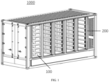
- FIG. 1 is a schematic structure diagram of an energy storage device 1000 according to some embodiments of the present application.
- the energy storage device 1000 is internally provided with a battery 100 and a cabinet frame 200.
- the battery 100 may be arranged on the cabinet frame 200.
- a plurality of batteries 100 may be stacked from top to bottom between cabinet frames 200.
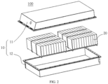
- FIG. 2 is an exploded view of a battery 100 according to some embodiments of the present application.
- the battery 100 includes a case 10 and a battery cell 20.
- the battery cell 20 is accommodated in the case 10.
- the case 10 is configured to provide an accommodating space for the battery cell 20, and the case 10 may be of various structures.
- the case 10 may include a first portion 11 and a second portion 12. The first portion 11 and the second portion 12 are fitted to each other in a covering manner, and the first portion 11 and the second portion 12 jointly define the accommodating space for accommodating the battery cell 20.
- the second portion 12 may be of a hollow structure with one end open, the first portion 11 may be of a plate-like structure, and the first portion 11 covers an open side of the second portion 12 such that the first portion 11 and the second portion 12 jointly define the accommodating space; and the first portion 11 and the second portion 12 may also each be of a hollow structure with one side open, and the open side of the first portion 11 covers the open side of the second portion 12.
- the case 10 formed by the first portion 11 and the second portion 12 may be in various shapes, such as a cylinder and a cuboid.
- a plurality of battery cells 20 may be provided.
- the plurality of battery cells 20 may be in series connection, in parallel connection, or in parallel-series connection.
- the parallel-series connection means that some of the plurality of battery cells 20 are connected in series and some are connected in parallel.
- the plurality of battery cells 20 may be directly connected together in series, or in parallel, or in series-parallel, and then a whole composed of the plurality of battery cells 20 is accommodated in the case 10.
- the battery 100 may also be a unit accommodated in the case 10 that is formed by firstly connecting a plurality of battery cells 20 in series or in parallel or in series-parallel to form a plurality of battery modules, and then connecting the plurality of battery modules in series or in parallel or in series-parallel.
- the battery 100 may further include other structures.
- the battery 100 may further include a busbar component configured to achieve electrical connections between the multiple battery cells 20.
- the battery cell 20 may be a secondary battery or a primary battery, and may be a lithium-sulfur battery, a sodium-ion battery, or a magnesium-ion battery, but is not limited thereto.
- the battery cell 20 may be in the shape of a cylinder, a flat body, a cuboid, etc.
- FIG. 3 is a schematic exploded view of a battery cell 20 according to some embodiments of the present application.
- the battery cell 20 may include an electrode assembly 21, a shell 22, an end cap 23, and an electrolyte (not shown in the figure).
- the electrode assembly 21 may include a positive electrode plate, a negative electrode plate, and a separator (none is shown in the figure).
- the battery cell 20 works primarily by moving metal ions between the positive electrode plate and the negative electrode plate.
- the positive electrode plate includes a positive current collector and a positive active material layer. A surface of the positive current collector is coated with the positive active material layer.
- the positive current collector includes a positive current collecting portion coated with the positive active material layer.
- the positive current collector may be made of aluminum, and the positive active material layer includes a positive active material which may be lithium cobalt oxides, lithium iron phosphate, ternary lithium, lithium manganate, etc.
- the negative electrode plate includes a negative current collector and a negative active material layer. A surface of the negative current collector is coated with the negative active material layer.
- the negative collector includes a negative current collecting portion coated with the negative active material layer.
- the negative current collector may be made of copper, and the negative active material layer includes a negative active material which may be carbon, silicon, etc.
- the separator may be made of polypropylene (PP), polyethylene (PE), etc.
- the electrode assembly 21 may be of a wound structure or a laminated structure, but the embodiments of the present application are not limited thereto.
- the shell 22 may have an opening at one end or have openings at both ends.
- the end cap 23 covers the opening of the shell 22 to form, together with the shell 22, an accommodating space for accommodating the electrode assembly 21 and the electrolyte.
- the shell 22 and the end cap 23 can be made of the same material, for example, the shell 22 and the end cap 23 can be both made of aluminum, so that the shell 22 and the end cap 23 can be welded conveniently.
- the shell 22 and the end cap 23 can also be made of different materials, for example, the shell 22 and the end cap 23 can be made of different metals, and the shell 22 and the end cap 23 can be connected by riveting or other manners.
- FIG. 4 is a schematic partial view of an energy storage device 1000 according to some embodiments of the present application
- FIG. 5 is an enlarged view of region A in FIG. 4
- a plurality of batteries 100 are stacked in a space formed by a plurality of cabinet frames 200, and the plurality of batteries 100 are electrically connected to each other by means of wire harnesses 300.
- a wire harness cover 30 is arranged on a case 10 of a battery, and the wire harness 300 passes through the wire harness cover 30 and is electrically connected to the battery 100 inside the case 10.
- FIG. 6 is an exploded view of a waterproof assembly according to some embodiments of the present application
- FIG. 7 is a schematic diagram of connection between a single wire harness cover 30 and a battery case 10 according to some embodiments of the present application
- FIG. 8 is a schematic cross-sectional structure view of region C in FIG. 7 in direction B-B.
- the present application provides a waterproof assembly of the energy storage device 1000.
- the waterproof assembly includes a boss 40 and a wire harness cover 30.
- the boss 40 is arranged on an outer wall of a case 10 of a battery, the boss 40 includes a first outward protruding portion 41, the first outward protruding portion 41 defines a first through hole 401, and the first through hole 401 is in communication with the interior of the case 10.
- the wire harness cover 30 is configured as a hollow cavity structure for receiving a wire harness 300, the wire harness cover 30 internally includes a first recess 301, and the first recess 301 is configured to accommodate the first outward protruding portion 41 to communicate the first through hole 401 with the hollow cavity.
- the boss 40 is arranged on the outer wall of the case 10 and configured to be connected to the wire harness cover 30.
- the boss 40 may be made of metal such as iron, magnesium or aluminum, or engineering plastic such as polybutylece terephthalate (PBT).
- PBT polybutylece terephthalate
- the interior of the boss 40 may be of a hollow pipe structure to facilitate electrical connection between the wire harness 300 and the battery 100 through the hollow pipe of the boss 40.
- the exterior of the boss 40 may be of a simple geometric structure such as a cuboid, a cylinder, or a sphere, or may be a complex geometric structure composed of a cuboid, a cylinder, a sphere, or other simple geometric structures.
- the boss 40 includes a first outward protruding portion 41, the first outward protruding portion 41 may be arranged at an end of the boss 40 opposite to a side wall of the case 10 and extend toward an edge of the case 10 in a radial direction X of the boss 40.
- the first outward protruding portion 41 extends around the periphery of the boss 40 and internally defines a first through hole 401.
- the first through hole 401 may be in communication with the interior of the case 40 so as to allow the wire harness 300 to be electrically connected to the battery 100 through the first through hole 401.
- the wire harness cover 30 may be configured to be of a hollow cavity structure for receiving the wire harness 300.
- the exterior of the wire harness cover 30 may be of a simple geometric structure such as a cuboid, a cylinder or a sphere, or may be a complex geometric structure composed of a cuboid, a cylinder, a sphere or other simple geometric structures.
- the wire harness cover 30 may be made of metal such as iron, magnesium or aluminum, or engineering plastic such as PBT, or an elastic material such as rubber.
- the case 10 is provided with the boss 40 having the first outward protruding portion 41, and the wire harness cover 30 is internally provided with the first recess 301 in which the first outward protruding portion 41 can be accommodated.
- the wire harness cover 30 may encase the portion connected to the boss 41 so as to prevent rainwater from directly flowing into the wire harness cover 30 or the case 10, thereby improving the waterproof performance of the energy storage device 1000.
- the first outward protruding portion 41 is in interference-fit with the first recess 301 in an axial direction Y of the boss 41.
- the first outward protruding portion 41 is in interference-fit with the first recess 301 in the axial direction Y of the boss 41, that is, the diameter D1 of the outer side wall of the first outward protruding portion 41 in the axial direction is greater than the diameter D2 of the inner side wall of the first recess 301.
- the interference-fit means that, during a mechanical installation process, when parts need to fit closely together, under the action of the elasticity of material, the first recess 301 expands and deforms to sleeve on the first outward protruding portion 41, and then the first recess 301 is restored and applies a hooping force to the first outward protruding portion 41, so that the first outward protruding portion 41 fits closely with the first recess 301.
- the interference-fit connection is simple in structure, has little weakening effect on the strength of the first outward protruding portion 41 and the first recess 301, and has good impact resistance. Since the outer side wall of the first outward protruding portion 41 is in interference-fit with the inner wall of the first recess 301, the sealing performance of the wire harness cover 30 to the boss 40 is greatly improved.
- FIG. 9 is a schematic structure diagram of a boss 40 according to some embodiments of the present application
- FIG. 10 is a schematic cross-sectional structure view of the boss 40 shown in FIG. 9 in plane X-Y.
- the boss 40 includes a first end 40a and a second end 40b.
- the first end 40a is connected to a side wall of the case 10.
- the second end 40b is arranged opposite the first end 40a, and the second end 40b is provided with the first outward protruding portion 41.
- a second recess 402 is formed between the first end 40a and the first outward protruding portion 41, and the second recess 402 is configured to accommodate a portion of the wire harness cover 30.
- the boss 40 is provided with the second recess 402 to accommodate a portion of the wire harness cover 30 when the first outward protruding portion 41 is accommodated in the first recess 301, so that the sealing performance of the wire harness cover 30 to the boss 40 can be enhanced.
- FIG. 11 is a schematic structure diagram of a wire harness cover 30 according to some embodiments of the present application
- FIG. 12 is a front view of the wire harness cover 30 shown in FIG. 11
- FIG. 13 is a schematic cross-sectional structure view of the wire harness cover 30 shown in FIG. 11 from a top view
- FIG. 14 is a schematic cross-sectional structure view of the wire harness cover 30 shown in FIG. 11 in direction D-D.
- the wire harness cover 30 includes a mouth portion 31, a transition portion 32, and a tail portion 33.
- the mouth portion 31 is located at one end of the wire harness cover 30 connected to the boss 40, the mouth portion 31 is provided with an opening 310, and the first outward protruding portion 41 enters the hollow cavity of the wire harness cover 30 through the opening 310.
- the tail portion 33 is located at the other end of the wire harness cover 30, the tail portion 33 includes a second through hole 302, and the wire harness 300 enters the hollow cavity of the wire harness cover 30 through the second through hole 302.
- the transition portion 32 connects the mouth portion 31 with the tail portion 33, and the outer diameter D3 of one end of the transition portion 32 connected to the mouth portion 31 is greater than the outer diameter D4 of one end of the transition portion 32 connected to the tail portion 33.
- the mouth portion 31 is located at one end of the wire harness cover 30 connected to the boss 40 and configured to be connected to the boss 40.
- the mouth portion 31 may be provided with an opening 310, and the first outward protruding portion 41 enters the hollow cavity of the wire harness cover 30 through the opening 310 and is accommodated in the first recess 301.
- the mouth portion 31 may be made of engineering plastic such as PBT, or an elastic material such as rubber.
- the tail portion 33 is located at the other end of the wire harness cover 30 opposite to the mouth portion 31.
- the tail portion 33 may include a second through hole 302, and the wire harness 300 may enter the hollow cavity of the wire harness cover 30 through the second through hole 302, and then enter the first through hole 401 through the mouth portion 31 and is connected to the battery 100.
- the transition portion 32 is configured to connect the mouth portion 31 with the tail portion 33. As shown in FIG. 13 , the outer diameter D3 of one end of the transition portion 32 connected to the mouth portion 31 is greater than the outer diameter D4 of one end of the transition portion 32 connected to the tail portion 33.
- the wire harness cover 30 is configured such that the outer diameter D4 of the tail portion 33 is smaller than the outer diameter D3 of the mouth portion 31, so that the volume of the tail portion 33 can be reduced, and accordingly, the wire harness cover 30 occupies less volume of the energy storage device 1000, thereby increasing the energy density of the energy storage device 1000.
- the mouth portion 31 includes an opening section 311 and a connecting section 312.
- the opening section 311 is located at one end of the mouth portion 31 connected to the boss 40.
- the connecting section 32 is located at the other end of the mouth portion 31 and configured to connect the opening section 311 with the transition portion 32.
- the inner diameter D5 of the connecting section 312 is greater than the inner diameter D6 of the opening section 311, and the opening section 311, the connecting section 312 and the transition portion 32 jointly form the first recess 301.
- FIG. 15 is a schematic partial cross-sectional structure view of a wire harness cover 30 and a boss 40 according to some embodiments of the present application.
- the boss 40 further includes a second outward protruding portion 42, the second outward protruding portion 42 is located in the second recess 402, the second outward protruding portion 42 and the first outward protruding portion 41 form a third recess 403, and the third recess 403 is configured to accommodate at least a portion of the opening section 311 when the first outward protruding portion 41 is accommodated in the first recess 301, the at least a portion of the opening section 311 being in interference-fit with the third recess 403.
- the boss 40 is additionally provided with the third recess 403, and at least a portion of the opening section 311 is in interference-fit with the third recess 403, so that the sealing performance of the wire harness cover 30 to the boss 40 can be improved.
- FIG. 16 is a schematic partial cross-sectional structure view of another wire harness cover 30 and another boss 40 according to some embodiments of the present application.
- a portion of the opening section 311 in contact with the second outward protruding portion 42 is provided with a third outward protruding portion 313 extending toward the first end 40a, and the second outward protruding portion 42 is provided with a fourth recess 404 matching the third outward protruding portion 313 in shape.
- the boss 40 is additionally provided with the fourth recess 404, and the wire harness cover 30 is provided with the third outward protruding portion 313 matching the fourth recess 404, so that the sealing performance of the wire harness cover 30 to the boss 40 can be improved.
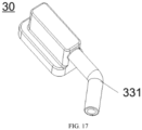
- FIG. 17 is a schematic structure diagram of a wire harness cover 30 including a bent tail pipe 331 according to some embodiments of the present application.
- the tail portion 33 includes a bent tail pipe 331, and an inner cavity of the bent tail pipe 331 is in communication with the second through hole 302.
- the bent tail pipe 331 prevents rainwater from directly flowing into the wire harness cover 30 from the second through hole 302, thereby enhancing the rainproof performance of the wire harness cover 30.
- the material of the wire harness cover 30 includes rubber.
- Rubber has good elasticity, and the connection between the wire harness cover 30 and the boss 40 can be made of rubber to improve the sealing performance of the wire harness cover 30.
- a waterproof assembly of the energy storage device 1000 provided in the present application includes a boss 40 and a wire harness cover 30.
- the boss 40 includes a first outward protruding portion 41, the first outward protruding portion 41 defines a first through hole 401, and the wire harness cover 30 internally includes a first recess 301.
- the first outward protruding portion 41 is in interference-fit with the first recess 301 in an axial direction of the boss 40.
- the boss 40 further includes a second recess 402, a third recess 403, a fourth recess 404, and a second outward protruding portion 42.
- the wire harness cover 30 includes a mouth portion 31, a transition portion 32 and a tail portion 33.
- the mouth portion 31 is provided with an opening 310, the mouth portion 31 includes an opening section 311 and a connecting section 312, and the opening section 311 is provided with a third outward protruding portion 313.
- the tail portion 33 includes a bent tail pipe 331, and an inner cavity of the bent tail pipe 331 forms the second through hole 302.
- the outer diameter D3 of one end of the transition portion 32 connected to the mouth portion 31 is greater than the outer diameter D4 of one end of the transition portion 32 connected to the tail portion 33.
- the mouth portion 31 of the wire harness cover 30 is made of rubber, the transition portion 32 and the tail portion 33 are made of PBT, and the boss 40 is made of metal aluminum.
- an energy storage device 1000 which includes a battery 100, a wire harness 300, and a waterproof assembly of any of the embodiments provided in the first aspect of the present application.
- the waterproof assembly is used to implement a waterproof function at the connection between the wire harness 300 and the battery 100.
- the energy storage device 1000 provided in the second aspect of the present application has a feature of good rainproof effect.
Landscapes
- Chemical & Material Sciences (AREA)
- Chemical Kinetics & Catalysis (AREA)
- Electrochemistry (AREA)
- General Chemical & Material Sciences (AREA)
- Engineering & Computer Science (AREA)
- Manufacturing & Machinery (AREA)
- Battery Mounting, Suspending (AREA)
Applications Claiming Priority (2)
| Application Number | Priority Date | Filing Date | Title |
|---|---|---|---|
| CN202122918062.9U CN216529216U (zh) | 2021-11-25 | 2021-11-25 | 储能装置的防水组件与储能装置 |
| PCT/CN2022/129373 WO2023093485A1 (zh) | 2021-11-25 | 2022-11-02 | 储能装置的防水组件与储能装置 |
Publications (3)
| Publication Number | Publication Date |
|---|---|
| EP4354585A1 true EP4354585A1 (de) | 2024-04-17 |
| EP4354585A4 EP4354585A4 (de) | 2025-04-02 |
| EP4354585B1 EP4354585B1 (de) | 2025-12-17 |
Family
ID=81533265
Family Applications (1)
| Application Number | Title | Priority Date | Filing Date |
|---|---|---|---|
| EP22897568.6A Active EP4354585B1 (de) | 2021-11-25 | 2022-11-02 | Wasserdichte anordnung für energiespeichervorrichtung und energiespeichervorrichtung |
Country Status (4)
| Country | Link |
|---|---|
| US (1) | US20240250364A1 (de) |
| EP (1) | EP4354585B1 (de) |
| CN (1) | CN216529216U (de) |
| WO (1) | WO2023093485A1 (de) |
Families Citing this family (1)
| Publication number | Priority date | Publication date | Assignee | Title |
|---|---|---|---|---|
| CN216529216U (zh) * | 2021-11-25 | 2022-05-13 | 宁德时代新能源科技股份有限公司 | 储能装置的防水组件与储能装置 |
Family Cites Families (8)
| Publication number | Priority date | Publication date | Assignee | Title |
|---|---|---|---|---|
| JPS5152668Y2 (de) * | 1971-07-06 | 1976-12-16 | ||
| JP2815081B2 (ja) * | 1993-02-18 | 1998-10-27 | 矢崎総業株式会社 | バッテリ間接続用コネクタ装置 |
| JP2001135289A (ja) * | 1999-11-03 | 2001-05-18 | Sanmooru Denshi Kk | 防滴型電池ケース |
| TWM401877U (en) * | 2010-11-08 | 2011-04-11 | han-xi Huang | Water-proof battery box |
| CN208596728U (zh) * | 2018-07-20 | 2019-03-12 | 黄河交通学院 | 一种共享汽车防水电池总成 |
| CN212461896U (zh) * | 2020-06-04 | 2021-02-02 | 万达电智能科技(昆山)有限公司 | 一种具有防水效果的锂电池外壳 |
| CN113659293A (zh) * | 2021-07-27 | 2021-11-16 | 深圳市立杰天源科技有限公司 | 一种避免正负极接触液体的锂电池保护板 |
| CN216529216U (zh) * | 2021-11-25 | 2022-05-13 | 宁德时代新能源科技股份有限公司 | 储能装置的防水组件与储能装置 |
-
2021
- 2021-11-25 CN CN202122918062.9U patent/CN216529216U/zh active Active
-
2022
- 2022-11-02 EP EP22897568.6A patent/EP4354585B1/de active Active
- 2022-11-02 WO PCT/CN2022/129373 patent/WO2023093485A1/zh not_active Ceased
-
2024
- 2024-03-08 US US18/599,244 patent/US20240250364A1/en active Pending
Also Published As
| Publication number | Publication date |
|---|---|
| WO2023093485A1 (zh) | 2023-06-01 |
| EP4354585A4 (de) | 2025-04-02 |
| CN216529216U (zh) | 2022-05-13 |
| EP4354585B1 (de) | 2025-12-17 |
| US20240250364A1 (en) | 2024-07-25 |
Similar Documents
| Publication | Publication Date | Title |
|---|---|---|
| US20240304918A1 (en) | Box of battery, battery, electrical apparatus, and manufacturing device for batteries | |
| US20240213544A1 (en) | Jelly-roll electrode assembly, battery cell, battery, and electrical device | |
| EP4498488A1 (de) | Endkappe, batteriezelle, batterie und elektrische vorrichtung | |
| US20240283062A1 (en) | Battery cell, battery, and power consuming device | |
| EP4358281A1 (de) | Elektrodenanordnung und leistungsbatterie | |
| US20250046934A1 (en) | Battery and electric apparatus | |
| EP4362171A1 (de) | Batteriekühlstruktur, batterie und stromverbrauchende vorrichtung | |
| US20230352743A1 (en) | Battery assembly and processing method and device therefor, battery cell, battery, and power consuming apparatus | |
| CN219303812U (zh) | 电池单体、电池及用电装置 | |
| KR102912908B1 (ko) | 전지 셀, 전지, 전기기기, 전지 셀의 제조 방법 및 장비 | |
| EP4726864A1 (de) | Batteriezelle, batterie und elektrische vorrichtung | |
| US20250392013A1 (en) | Battery cell, battery, and electric device | |
| CN117501532A (zh) | 电池单体、电池以及用电装置 | |
| US20240250364A1 (en) | Waterproof assembly of energy storage device, and energy storage device | |
| US20230361356A1 (en) | Battery unit, and battery, power consuming device and preparation apparatus associated therewith | |
| KR102913933B1 (ko) | 방식 부재가 구비된 버스 바 및 이를 포함하는 배터리 모듈 | |
| US20240222780A1 (en) | End plate, battery module, battery, electric device, and manufacturing method of end plate | |
| CN119627373B (zh) | 电池单体的制造方法、电池单体、电池及用电装置 | |
| CN219203426U (zh) | 电池及用电设备 | |
| EP4589754A1 (de) | Endkappenanordnung, batteriezelle, batterie und elektrische vorrichtung | |
| JP2025523928A (ja) | 電池セル、電池及び電力消費装置 | |
| KR20190067325A (ko) | 이차전지 모듈 | |
| CN222483631U (zh) | 壳体组件、电池单体、电池和用电装置 | |
| EP4318755A1 (de) | Batterie, elektrische vorrichtung sowie verfahren und vorrichtung zur herstellung der batterie | |
| CN221041294U (zh) | 电池单体、电池和用电装置 |
Legal Events
| Date | Code | Title | Description |
|---|---|---|---|
| STAA | Information on the status of an ep patent application or granted ep patent |
Free format text: STATUS: THE INTERNATIONAL PUBLICATION HAS BEEN MADE |
|
| PUAI | Public reference made under article 153(3) epc to a published international application that has entered the european phase |
Free format text: ORIGINAL CODE: 0009012 |
|
| STAA | Information on the status of an ep patent application or granted ep patent |
Free format text: STATUS: REQUEST FOR EXAMINATION WAS MADE |
|
| 17P | Request for examination filed |
Effective date: 20240109 |
|
| AK | Designated contracting states |
Kind code of ref document: A1 Designated state(s): AL AT BE BG CH CY CZ DE DK EE ES FI FR GB GR HR HU IE IS IT LI LT LU LV MC ME MK MT NL NO PL PT RO RS SE SI SK SM TR |
|
| RAP1 | Party data changed (applicant data changed or rights of an application transferred) |
Owner name: CONTEMPORARY AMPEREX TECHNOLOGY(HONG KONG) LIMITED |
|
| REG | Reference to a national code |
Ref country code: DE Free format text: PREVIOUS MAIN CLASS: H01M0010420000 Ref country code: DE Ref legal event code: R079 Ref document number: 602022027217 Country of ref document: DE Free format text: PREVIOUS MAIN CLASS: H01M0010420000 Ipc: H01M0050240000 |
|
| DAV | Request for validation of the european patent (deleted) | ||
| DAX | Request for extension of the european patent (deleted) | ||
| A4 | Supplementary search report drawn up and despatched |
Effective date: 20250303 |
|
| RIC1 | Information provided on ipc code assigned before grant |
Ipc: H01M 10/42 20060101ALI20250225BHEP Ipc: H01M 50/24 20210101AFI20250225BHEP |
|
| GRAP | Despatch of communication of intention to grant a patent |
Free format text: ORIGINAL CODE: EPIDOSNIGR1 |
|
| STAA | Information on the status of an ep patent application or granted ep patent |
Free format text: STATUS: GRANT OF PATENT IS INTENDED |
|
| RIC1 | Information provided on ipc code assigned before grant |
Ipc: H01M 50/24 20210101AFI20250911BHEP Ipc: H01M 10/42 20060101ALI20250911BHEP |
|
| GRAS | Grant fee paid |
Free format text: ORIGINAL CODE: EPIDOSNIGR3 |
|
| INTG | Intention to grant announced |
Effective date: 20251009 |
|
| GRAA | (expected) grant |
Free format text: ORIGINAL CODE: 0009210 |
|
| STAA | Information on the status of an ep patent application or granted ep patent |
Free format text: STATUS: THE PATENT HAS BEEN GRANTED |
|
| AK | Designated contracting states |
Kind code of ref document: B1 Designated state(s): AL AT BE BG CH CY CZ DE DK EE ES FI FR GB GR HR HU IE IS IT LI LT LU LV MC ME MK MT NL NO PL PT RO RS SE SI SK SM TR |
|
| REG | Reference to a national code |
Ref country code: CH Ref legal event code: F10 Free format text: ST27 STATUS EVENT CODE: U-0-0-F10-F00 (AS PROVIDED BY THE NATIONAL OFFICE) Effective date: 20251217 Ref country code: GB Ref legal event code: FG4D |
|
| REG | Reference to a national code |
Ref country code: DE Ref legal event code: R096 Ref document number: 602022027217 Country of ref document: DE |
|
| REG | Reference to a national code |
Ref country code: LT Ref legal event code: MG9D |
|
| PG25 | Lapsed in a contracting state [announced via postgrant information from national office to epo] |
Ref country code: NO Free format text: LAPSE BECAUSE OF FAILURE TO SUBMIT A TRANSLATION OF THE DESCRIPTION OR TO PAY THE FEE WITHIN THE PRESCRIBED TIME-LIMIT Effective date: 20260317 |
|
| PG25 | Lapsed in a contracting state [announced via postgrant information from national office to epo] |
Ref country code: FI Free format text: LAPSE BECAUSE OF FAILURE TO SUBMIT A TRANSLATION OF THE DESCRIPTION OR TO PAY THE FEE WITHIN THE PRESCRIBED TIME-LIMIT Effective date: 20251217 Ref country code: HR Free format text: LAPSE BECAUSE OF FAILURE TO SUBMIT A TRANSLATION OF THE DESCRIPTION OR TO PAY THE FEE WITHIN THE PRESCRIBED TIME-LIMIT Effective date: 20251217 |
|
| PG25 | Lapsed in a contracting state [announced via postgrant information from national office to epo] |
Ref country code: RS Free format text: LAPSE BECAUSE OF FAILURE TO SUBMIT A TRANSLATION OF THE DESCRIPTION OR TO PAY THE FEE WITHIN THE PRESCRIBED TIME-LIMIT Effective date: 20260317 |
|
| REG | Reference to a national code |
Ref country code: NL Ref legal event code: MP Effective date: 20251217 |
|
| PG25 | Lapsed in a contracting state [announced via postgrant information from national office to epo] |
Ref country code: LV Free format text: LAPSE BECAUSE OF FAILURE TO SUBMIT A TRANSLATION OF THE DESCRIPTION OR TO PAY THE FEE WITHIN THE PRESCRIBED TIME-LIMIT Effective date: 20251217 |