EP4354596B1 - Battery module - Google Patents
Battery module Download PDFInfo
- Publication number
- EP4354596B1 EP4354596B1 EP23164484.0A EP23164484A EP4354596B1 EP 4354596 B1 EP4354596 B1 EP 4354596B1 EP 23164484 A EP23164484 A EP 23164484A EP 4354596 B1 EP4354596 B1 EP 4354596B1
- Authority
- EP
- European Patent Office
- Prior art keywords
- central wall
- module
- sub
- battery module
- groove
- Prior art date
- Legal status (The legal status is an assumption and is not a legal conclusion. Google has not performed a legal analysis and makes no representation as to the accuracy of the status listed.)
- Active
Links
Images


Classifications
-
- H—ELECTRICITY
- H01—ELECTRIC ELEMENTS
- H01M—PROCESSES OR MEANS, e.g. BATTERIES, FOR THE DIRECT CONVERSION OF CHEMICAL ENERGY INTO ELECTRICAL ENERGY
- H01M50/00—Constructional details or processes of manufacture of the non-active parts of electrochemical cells other than fuel cells, e.g. hybrid cells
- H01M50/20—Mountings; Secondary casings or frames; Racks, modules or packs; Suspension devices; Shock absorbers; Transport or carrying devices; Holders
- H01M50/249—Mountings; Secondary casings or frames; Racks, modules or packs; Suspension devices; Shock absorbers; Transport or carrying devices; Holders specially adapted for aircraft or vehicles, e.g. cars or trains
-
- H—ELECTRICITY
- H01—ELECTRIC ELEMENTS
- H01M—PROCESSES OR MEANS, e.g. BATTERIES, FOR THE DIRECT CONVERSION OF CHEMICAL ENERGY INTO ELECTRICAL ENERGY
- H01M10/00—Secondary cells; Manufacture thereof
- H01M10/60—Heating or cooling; Temperature control
- H01M10/61—Types of temperature control
- H01M10/613—Cooling or keeping cold
-
- H—ELECTRICITY
- H01—ELECTRIC ELEMENTS
- H01M—PROCESSES OR MEANS, e.g. BATTERIES, FOR THE DIRECT CONVERSION OF CHEMICAL ENERGY INTO ELECTRICAL ENERGY
- H01M10/00—Secondary cells; Manufacture thereof
- H01M10/60—Heating or cooling; Temperature control
- H01M10/64—Heating or cooling; Temperature control characterised by the shape of the cells
- H01M10/647—Prismatic or flat cells, e.g. pouch cells
-
- H—ELECTRICITY
- H01—ELECTRIC ELEMENTS
- H01M—PROCESSES OR MEANS, e.g. BATTERIES, FOR THE DIRECT CONVERSION OF CHEMICAL ENERGY INTO ELECTRICAL ENERGY
- H01M10/00—Secondary cells; Manufacture thereof
- H01M10/60—Heating or cooling; Temperature control
- H01M10/65—Means for temperature control structurally associated with the cells
- H01M10/655—Solid structures for heat exchange or heat conduction
- H01M10/6554—Rods or plates
-
- H—ELECTRICITY
- H01—ELECTRIC ELEMENTS
- H01M—PROCESSES OR MEANS, e.g. BATTERIES, FOR THE DIRECT CONVERSION OF CHEMICAL ENERGY INTO ELECTRICAL ENERGY
- H01M10/00—Secondary cells; Manufacture thereof
- H01M10/60—Heating or cooling; Temperature control
- H01M10/65—Means for temperature control structurally associated with the cells
- H01M10/655—Solid structures for heat exchange or heat conduction
- H01M10/6556—Solid parts with flow channel passages or pipes for heat exchange
-
- H—ELECTRICITY
- H01—ELECTRIC ELEMENTS
- H01M—PROCESSES OR MEANS, e.g. BATTERIES, FOR THE DIRECT CONVERSION OF CHEMICAL ENERGY INTO ELECTRICAL ENERGY
- H01M10/00—Secondary cells; Manufacture thereof
- H01M10/60—Heating or cooling; Temperature control
- H01M10/65—Means for temperature control structurally associated with the cells
- H01M10/658—Means for temperature control structurally associated with the cells by thermal insulation or shielding
-
- H—ELECTRICITY
- H01—ELECTRIC ELEMENTS
- H01M—PROCESSES OR MEANS, e.g. BATTERIES, FOR THE DIRECT CONVERSION OF CHEMICAL ENERGY INTO ELECTRICAL ENERGY
- H01M50/00—Constructional details or processes of manufacture of the non-active parts of electrochemical cells other than fuel cells, e.g. hybrid cells
- H01M50/20—Mountings; Secondary casings or frames; Racks, modules or packs; Suspension devices; Shock absorbers; Transport or carrying devices; Holders
- H01M50/204—Racks, modules or packs for multiple batteries or multiple cells
-
- H—ELECTRICITY
- H01—ELECTRIC ELEMENTS
- H01M—PROCESSES OR MEANS, e.g. BATTERIES, FOR THE DIRECT CONVERSION OF CHEMICAL ENERGY INTO ELECTRICAL ENERGY
- H01M50/00—Constructional details or processes of manufacture of the non-active parts of electrochemical cells other than fuel cells, e.g. hybrid cells
- H01M50/20—Mountings; Secondary casings or frames; Racks, modules or packs; Suspension devices; Shock absorbers; Transport or carrying devices; Holders
- H01M50/204—Racks, modules or packs for multiple batteries or multiple cells
- H01M50/207—Racks, modules or packs for multiple batteries or multiple cells characterised by their shape
- H01M50/209—Racks, modules or packs for multiple batteries or multiple cells characterised by their shape adapted for prismatic or rectangular cells
-
- H—ELECTRICITY
- H01—ELECTRIC ELEMENTS
- H01M—PROCESSES OR MEANS, e.g. BATTERIES, FOR THE DIRECT CONVERSION OF CHEMICAL ENERGY INTO ELECTRICAL ENERGY
- H01M50/00—Constructional details or processes of manufacture of the non-active parts of electrochemical cells other than fuel cells, e.g. hybrid cells
- H01M50/20—Mountings; Secondary casings or frames; Racks, modules or packs; Suspension devices; Shock absorbers; Transport or carrying devices; Holders
- H01M50/233—Mountings; Secondary casings or frames; Racks, modules or packs; Suspension devices; Shock absorbers; Transport or carrying devices; Holders characterised by physical properties of casings or racks, e.g. dimensions
-
- H—ELECTRICITY
- H01—ELECTRIC ELEMENTS
- H01M—PROCESSES OR MEANS, e.g. BATTERIES, FOR THE DIRECT CONVERSION OF CHEMICAL ENERGY INTO ELECTRICAL ENERGY
- H01M50/00—Constructional details or processes of manufacture of the non-active parts of electrochemical cells other than fuel cells, e.g. hybrid cells
- H01M50/20—Mountings; Secondary casings or frames; Racks, modules or packs; Suspension devices; Shock absorbers; Transport or carrying devices; Holders
- H01M50/233—Mountings; Secondary casings or frames; Racks, modules or packs; Suspension devices; Shock absorbers; Transport or carrying devices; Holders characterised by physical properties of casings or racks, e.g. dimensions
- H01M50/24—Mountings; Secondary casings or frames; Racks, modules or packs; Suspension devices; Shock absorbers; Transport or carrying devices; Holders characterised by physical properties of casings or racks, e.g. dimensions adapted for protecting batteries from their environment, e.g. from corrosion
-
- H—ELECTRICITY
- H01—ELECTRIC ELEMENTS
- H01M—PROCESSES OR MEANS, e.g. BATTERIES, FOR THE DIRECT CONVERSION OF CHEMICAL ENERGY INTO ELECTRICAL ENERGY
- H01M50/00—Constructional details or processes of manufacture of the non-active parts of electrochemical cells other than fuel cells, e.g. hybrid cells
- H01M50/20—Mountings; Secondary casings or frames; Racks, modules or packs; Suspension devices; Shock absorbers; Transport or carrying devices; Holders
- H01M50/258—Modular batteries; Casings provided with means for assembling
-
- H—ELECTRICITY
- H01—ELECTRIC ELEMENTS
- H01M—PROCESSES OR MEANS, e.g. BATTERIES, FOR THE DIRECT CONVERSION OF CHEMICAL ENERGY INTO ELECTRICAL ENERGY
- H01M50/00—Constructional details or processes of manufacture of the non-active parts of electrochemical cells other than fuel cells, e.g. hybrid cells
- H01M50/20—Mountings; Secondary casings or frames; Racks, modules or packs; Suspension devices; Shock absorbers; Transport or carrying devices; Holders
- H01M50/262—Mountings; Secondary casings or frames; Racks, modules or packs; Suspension devices; Shock absorbers; Transport or carrying devices; Holders with fastening means, e.g. locks
-
- H—ELECTRICITY
- H01—ELECTRIC ELEMENTS
- H01M—PROCESSES OR MEANS, e.g. BATTERIES, FOR THE DIRECT CONVERSION OF CHEMICAL ENERGY INTO ELECTRICAL ENERGY
- H01M50/00—Constructional details or processes of manufacture of the non-active parts of electrochemical cells other than fuel cells, e.g. hybrid cells
- H01M50/20—Mountings; Secondary casings or frames; Racks, modules or packs; Suspension devices; Shock absorbers; Transport or carrying devices; Holders
- H01M50/262—Mountings; Secondary casings or frames; Racks, modules or packs; Suspension devices; Shock absorbers; Transport or carrying devices; Holders with fastening means, e.g. locks
- H01M50/264—Mountings; Secondary casings or frames; Racks, modules or packs; Suspension devices; Shock absorbers; Transport or carrying devices; Holders with fastening means, e.g. locks for cells or batteries, e.g. straps, tie rods or peripheral frames
-
- H—ELECTRICITY
- H01—ELECTRIC ELEMENTS
- H01M—PROCESSES OR MEANS, e.g. BATTERIES, FOR THE DIRECT CONVERSION OF CHEMICAL ENERGY INTO ELECTRICAL ENERGY
- H01M50/00—Constructional details or processes of manufacture of the non-active parts of electrochemical cells other than fuel cells, e.g. hybrid cells
- H01M50/20—Mountings; Secondary casings or frames; Racks, modules or packs; Suspension devices; Shock absorbers; Transport or carrying devices; Holders
- H01M50/271—Lids or covers for the racks or secondary casings
-
- H—ELECTRICITY
- H01—ELECTRIC ELEMENTS
- H01M—PROCESSES OR MEANS, e.g. BATTERIES, FOR THE DIRECT CONVERSION OF CHEMICAL ENERGY INTO ELECTRICAL ENERGY
- H01M50/00—Constructional details or processes of manufacture of the non-active parts of electrochemical cells other than fuel cells, e.g. hybrid cells
- H01M50/20—Mountings; Secondary casings or frames; Racks, modules or packs; Suspension devices; Shock absorbers; Transport or carrying devices; Holders
- H01M50/289—Mountings; Secondary casings or frames; Racks, modules or packs; Suspension devices; Shock absorbers; Transport or carrying devices; Holders characterised by spacing elements or positioning means within frames, racks or packs
-
- H—ELECTRICITY
- H01—ELECTRIC ELEMENTS
- H01M—PROCESSES OR MEANS, e.g. BATTERIES, FOR THE DIRECT CONVERSION OF CHEMICAL ENERGY INTO ELECTRICAL ENERGY
- H01M50/00—Constructional details or processes of manufacture of the non-active parts of electrochemical cells other than fuel cells, e.g. hybrid cells
- H01M50/20—Mountings; Secondary casings or frames; Racks, modules or packs; Suspension devices; Shock absorbers; Transport or carrying devices; Holders
- H01M50/289—Mountings; Secondary casings or frames; Racks, modules or packs; Suspension devices; Shock absorbers; Transport or carrying devices; Holders characterised by spacing elements or positioning means within frames, racks or packs
- H01M50/291—Mountings; Secondary casings or frames; Racks, modules or packs; Suspension devices; Shock absorbers; Transport or carrying devices; Holders characterised by spacing elements or positioning means within frames, racks or packs characterised by their shape
-
- H—ELECTRICITY
- H01—ELECTRIC ELEMENTS
- H01M—PROCESSES OR MEANS, e.g. BATTERIES, FOR THE DIRECT CONVERSION OF CHEMICAL ENERGY INTO ELECTRICAL ENERGY
- H01M2220/00—Batteries for particular applications
- H01M2220/20—Batteries in motive systems, e.g. vehicle, ship, plane
-
- Y—GENERAL TAGGING OF NEW TECHNOLOGICAL DEVELOPMENTS; GENERAL TAGGING OF CROSS-SECTIONAL TECHNOLOGIES SPANNING OVER SEVERAL SECTIONS OF THE IPC; TECHNICAL SUBJECTS COVERED BY FORMER USPC CROSS-REFERENCE ART COLLECTIONS [XRACs] AND DIGESTS
- Y02—TECHNOLOGIES OR APPLICATIONS FOR MITIGATION OR ADAPTATION AGAINST CLIMATE CHANGE
- Y02E—REDUCTION OF GREENHOUSE GAS [GHG] EMISSIONS, RELATED TO ENERGY GENERATION, TRANSMISSION OR DISTRIBUTION
- Y02E60/00—Enabling technologies; Technologies with a potential or indirect contribution to GHG emissions mitigation
- Y02E60/10—Energy storage using batteries
Definitions
- the present disclosure relates to a battery module.
- each sub-module has been manufactured individually.
- US Patent Application 20190198831 A1 discloses an energy storage apparatus comprising a plurality of energy storage devices stacked in a first direction and coupled to each other by a connecting member, that may be decoupled, and an intermediate member.
- the disclosed configuration facilitates exchange of some of the energy storage devices without the need to exchange the entire battery module.
- rectangular parts are connected to each other using a concavo-convex fitting engagement.
- European Patent Application 3641004 A1 discloses a battery module comprising a cell stack that includes a plurality of cells stacked in a first direction and a coupling part.
- the coupling part is configured to be coupled to the coupling part of an adjacent battery module.
- the coupling part may include fastening parts at a first and at a second wall.
- a guide groove that may be disposed between the fastening part and a tube receiving opening, may be configured in a geometry to receive guide pins of a second module housing.
- European Patent Application 0065349 A1 discloses a battery pack comprising a plurality of individual cell containers clamped together in a way that a small ventilation gap is maintained for the sake of cooling.
- interlocks are disclosed that contain at least one set of complementary shaped (e.g., male and female) projections on juxtaposed walls of adjacent containers.
- Present disclosure provides a simplified process of manufacturing a battery module including a plurality of same sub-modules.
- Present disclosure provides a battery module in which a central wall is connected to a side cover to have improved mechanical rigidity.
- Present disclosure provides a battery module capable of preventing heat from propagating to adjacent sub-modules by coupling a sub-module and a central wall.
- a battery module comprises a battery module including: a first sub-module and a second sub-module respectively including a cell stack in which a plurality of battery cells are stacked; and a central wall disposed between the first sub-module and the second sub-module, wherein the central wall includes a first central wall facing the first sub-module and a second central wall facing the second sub-module, wherein the first central wall has a rotationary symmetrical shape of the second central wall around a first axis.
- the first central wall may be coupled to the first sub-module, and the second central wall may be coupled to the second sub-module.
- the first sub-module and the second sub-module may have the same structure.
- first central wall and the second central wall may have the same structure.
- the battery module may further include a side cover protecting the first sub-module, and the central wall may be coupled to the side cover.
- the central wall may include a first fastening groove, and the central wall may be coupled to the side cover through a fastening member and the first fastening groove.
- the battery module may further include an upper cover covering upper portions of the first sub-module and the second sub-module; and a lower cover covering lower portions of the first sub-module and the second sub-module, wherein the central wall may be coupled to the upper cover and the lower cover.
- the central wall may include a second fastening groove, and the central wall may be coupled to the upper cover and the lower cover through a fastening member and the second fastening groove.
- the central wall includes a guide groove and a guide protrusion, which may be formed on one surface thereof, and which are disposed to face each other.
- the guide groove and the guide protrusion are disposed to be rotationally symmetrical with respect to a centerline passing through a center of the central wall.
- the guide groove of the first central wall and the guide groove of the second central wall are disposed to be rotationally symmetrical around the first axis.
- the guide groove of the first central wall is in contact with the guide protrusion of the second central wall, and the guide protrusion of the first central wall is in contact with the guide groove of the second central wall.
- the central wall may include a plurality of groove portions on one surface thereof.
- the plurality of groove portions may expand inwardly from an outer surface of the central wall to an inner side of the center wall.
- the plurality of groove portions of the first central wall may extend in a first direction and have depth in a second direction perpendicular to the first direction and be formed in a direction, from the first central wall toward the first sub-module, and the plurality of groove portions of the second central wall may extend in the first direction and have depth in the second direction and be formed in a direction, from the second central wall toward the second sub-module.
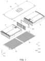
- FIG. 1 is an exploded perspective view of a battery module according to one embodiment of the present disclosure.
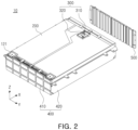
- FIG. 2 is a perspective view of a sub-module according to an embodiment of the present disclosure.
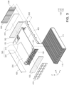
- FIG. 3 is an exploded perspective view of the sub-module illustrated in FIG. 2 .
- a battery module 1 of the present disclosure may include a sub-module 10 including a central wall 500, and an upper cover 20 and a lower cover 30 covering the sub-module 10.
- the sub-module 10 may include a first sub-module 11 and a second sub-module 12, and the first submodule 11 and the second submodule 12 may be disposed to face each other with the central wall 500 interposed therebetween.
- the first sub-module 11 and the second sub-module 12 may be formed to have the same structure. That is, the first sub-module 11 and the second sub-module 12 may include the same components (e.g., a cell assembly or a protective cover), and may be manufactured through the same manufacturing process.
- the second sub-module 12 may be in a state in which the first sub-module 11 is rotated by 180° around a first direction (Z-direction), as an axis.
- first sub-module 11 and the second sub-module 12 may be disposed to be rotationally symmetrical around a first axis (Z-axis).
- the first sub-module 11 and the second sub-module 12 may be disposed to face each other in a second direction (X-direction), perpendicular to the first direction (Z-direction).
- the first sub-module 11 may include a first central wall 510 and the second sub-module 12 may include a second central wall 520.
- the first central wall 510 and the second central wall 520 may be disposed between the first sub-module 11 and the second sub-module 12.
- the central wall 500 may block heat propagation between adjacent sub-modules 10.
- the central wall 500 may include the first central wall 510 and the second central wall 520.
- the first central wall 510 and the second central wall 520 may be formed to have the same structure. That is, the first central wall 510 and the second central wall 520 may include the same components, and may be manufactured through the same manufacturing process. For example, a plurality of grooves may be formed on one surface of the first central wall 510 and the second central wall 520 in the same manner.
- the second central wall 520 may be in a state in which the first central wall 510 is rotated by 180° around the first direction (Z-direction), as an axis. That is, the first central wall 510 and the second central wall 520 may be disposed to be rotationally symmetrical around the first axis (Z-axis).
- the battery module 1 may include an upper cover 20 disposed above the sub-module 10 and a lower cover 30 disposed below the sub-module 10.
- the upper cover 20 may be disposed to cover upper surfaces of the first and second sub-modules 11 and 12
- the lower cover 30 may be disposed to cover lower surfaces of the first and secondsub-modules 11 and 12.
- the battery module 1 may include a housing covering the first and second sub-modules 11 and 12.
- the housing may protect all of the upper portions, lower portions, and side surfaces of the first and second sub-modules 11 and 12.
- the housing may additionally include a side cover to cover the first and second sub-modules 11 and 12.
- the upper cover 20 may include an opening 21. As shown in FIG. 2 , a sensing terminal 310 may be disposed on an outer surface of the upper cover 20 due to the opening 21. Therefore, even if the upper cover 20 covers the upper portions of the first and second sub-modules 11 and 12, the sensing terminal 310 may be exposed to an upper side thereof (e.g., in the Z-direction) through the opening 21 to be connected to an external circuit.
- a heat conducting member may be disposed between the lower cover 30 and the first and secondsub-modules 11 and 12. One surface of the heat conducting member may contact the sub-module 10 and the other surface may contact the lower cover 30.
- the heat conducting member may include a thermal adhesive.
- a heat sink 40 may be disposed on the lower cover 30.
- a cooling passage may be formed in the heat sink 40.
- one heat sink 40 may be formed to cover all of the first and second sub-modules 11 and 12.
- a structure of the heat sink 40 is not limited thereto.
- a plurality of heat sinks 40 may be provided and configured to respectively correspond to the first and second sub-modules 11 and 12.
- the sub-module 10 may include a cell assembly 100 in which a plurality of battery cells 111 are stacked in a third direction (Y-direction), and a protective cover 400 protecting the cell assembly 100 and a central wall 500.
- the protective cover 400 may protect the plurality of battery cells 111 from external impacts.
- the cell assembly 100 may include a cell stack 110 including battery cells 111 stacked in a third direction (Y-direction), a busbar assembly 120 electrically connected to the cell stack 110, and an insulating cover 130 coupled to the busbar assembly 120.
- the cell stack 110 may include one or more battery cells 111.
- the plurality of battery cells 111 included in the cell stack 110 may be pouch-type battery cells 111.
- the battery cell 111 may convert chemical energy into electrical energy to supply power to an external circuit or receive power from the outside to convert electrical energy into chemical energy and store the same therein.
- the battery cell 111 is not limited to a pouch-type battery cell.
- the type of battery cell 111 may be a prismatic battery cell or a cylindrical battery cell.
- the busbar assembly 120 may electrically connect the battery cells 111 accommodated in the cell assembly 100, and may include a terminal unit 121 connected externally.
- a plurality of busbar assemblies 120 may be disposed to be connected to the cell stack 110, and may be provided on both one side surface and the other side surface of the cell stack 110, facing each other.
- the busbar assembly 120 may be disposed on one side surface of the cell stack 110, and the terminal unit 121 may be connected to one side surface of an upper plate member 200.
- the terminal unit 121 may include a positive electrode terminal and a negative electrode terminal, and may be disposed to be spaced apart from each other.
- the cell assembly 100 may include an insulating cover 130 coupled to the busbar assembly 120.
- the insulating cover 130 may be connected to the busbar assembly 120 and may block electrical connection between the busbar assembly 120 and an end cover 410.
- the sub-module 10 may be connected to the cell assembly 100, and may include an upper plate member 200 disposed above the cell assembly 100.
- a sensing module 300 may be disposed on the upper plate member 200.
- a sensing terminal 310 may be disposed on one side of the upper plate member 200 disposed on the central wall 500, and a terminal unit 121 may be connected to the other side of the upper plate member 200 on which the central wall 500 is not disposed.
- the sensing module 300 may sense electrical and thermal states of the battery cells 111 included in the cell assembly 100.
- the sensing module 300 may be disposed above the cell assembly 100, and may be connected to a plurality of battery cells 111.
- the sensing module 300 may include a sensing terminal 310 and a sensing circuit 320.
- the sensing circuit 320 forms a circuit for sensing electrical and thermal states of the plurality of battery cells 111.
- the sensing circuit 320 may be connected to the busbar assembly 120, and electrically connected to the battery cells 111.
- the sensing terminal 310 may be connected to the sensing circuit 320 and may be connected externally.
- the sensing terminal 310 may be connected to the upper cover 20.
- the sensing terminal 310 may be disposed on the other side surface of the upper plate member 200 facing one side surface of the upper plate member 200 to which the terminal unit 121 is connected.
- the sub-module 10 may include a protective cover 400 coupled to the cell assembly 100.
- the protective cover 400 may include a plurality of end covers 410 and a plurality of side covers 420 covering at least one side of the cell assembly 100.
- a lower portion of the cell assembly 100 may directly contact a heat sink 40 without being covered by the protective cover 400. Accordingly, the cell assembly 100 directly contacts the heat sink 40 (shown in FIG. 1 ), so that the cooling efficiency of the battery module may be improved.
- the end cover 410 may be disposed on a side on which the busbar assembly 120 is disposed in the sub-module 10, to cover the sub module 10.
- a plurality of end covers 410 may be provided, may be disposed on both sides thereof, and may be connected to the insulating cover 130.
- an end cover 410, the insulating cover 130, the busbar assembly 120, and the cell stack 110 may be sequentially disposed on one side surface of the sub-module 10. That is, the end cover 410 may be disposed on both ends of the sub-module 10, and may protect the cell assembly 100 from external impacts or the external environment.
- the side cover 420 may protect a side surface of the cell assembly 100.
- the side cover 420 may be disposed on a side surface of the cell assembly 100, and may be disposed to face a cell body unit of the stacked battery cells 111.
- the sub-module 10 may include a central wall 500 coupled to the cell assembly 100.
- the central wall 500 may be disposed on a side of the sub-module 10 on which the sensing module 300 is disposed, to cover the sub module 10.
- the central wall 500 may be provided on only one side of the sub-module, and may protect the cell assembly 100.
- the central wall 500 may be coupled to the side cover 420.
- the fastening member 600 may couple the central wall 500 and the side cover 420.
- Each of the central wall 500 and the side cover 420 may include a first fastening groove 540 corresponding to the fastening member 600.
- a plurality of first fastening grooves 540 may be provided.
- the central wall 500 and the side cover 420 may be fixed by the fastening member(s) 600, and thus mechanical rigidity of the sub-module 10 may be improved, and structural stability may be obtained.
- a side cover was not fixed in a process of manufacturing the sub-module, and accordingly, the side cover was fixed and used by applying force from the outside.
- the battery module 1 of the embodiments of the present disclosure since the side cover 420 and the central wall 500 are coupled so that the side cover 420 may be fixed, manufacturing process may be simplified.
- the sub-modules included in the battery module have different structures, so that each of the sub-modules had to be individually manufactured.
- the same sub-module 10 may be repeatedly manufactured and connected.
- the central wall 500 having the same structure may be repeatedly manufactured and coupled to the sub-module 10. Accordingly, the battery module 1 may be produced by connecting the sub-module 10 connected to the central wall 500, and a manufacturing process of the battery module 1 may be simplified.
- the central wall 500 may perform a function of blocking heat propagation between adjacent sub-modules 10. For example, heat generated in sub-module 10 may be prevented from propagating to adjacent sub-modules 10.
- the central wall 500 may be formed of a member having low thermal conductivity.
- the flame retardant material such as flame retardant plastic
- ceramic coated metal, mica coated metal or flame retardant polymer coated metal can be used to form the central wall 500, but the present disclosure is not limited thereto.
- a groove portion may be formed in the central wall 500, and thus a space may be formed inside the central wall 500. Accordingly, the internal space of the central wall 500 may perform a heat insulating function of blocking heat propagation.
- FIG. 4 is an exploded perspective view of a central wall according to an embodiment of the present disclosure.
- FIG. 5A is a perspective view of the central wall illustrated in FIG. 4 .
- FIG. 5B is a plan view of the central wall shown in FIG. 5A .
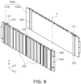
- FIG. 6 is an exploded perspective view of a central wall according to another embodiment of the present disclosure.
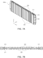
- FIG. 7A is a perspective view illustrating the central wall illustrated in FIG. 6 .
- FIG. 7B is a plan view of the central wall illustrated in FIG. 7A .
- the central wall 500 may be formed to have a length in a third direction (Y-direction).
- the central wall 500a (shown in FIG. 4 ) may include a plurality of groove portions 530, and may include a guide groove 560 and a guide protrusion 570 to be coupled to each other.
- the central wall 500a may include a first central wall 510a and a second central wall 520a.
- the first central wall 510a may have the same structure as the second central wall 520a.
- the first central wall 510a and the second central wall 520a may be rotated by 180° around a first axis.
- the first central wall 510a and the second central wall 520a may be manufactured to be the same as each other and coupled to the sub-module 10 having the same structure, and a manufacturing process of the battery module 1 may be simplified.
- the first central wall 510a and the second central wall 520a may include a guide groove 560 and a guide protrusion 570 on one surface thereof, respectively. While the first central wall 510a and the second central wall 520a contact each other, one surface on which the guide groove 560 and the guide protrusion 570 are formed may be in contact with each other.
- a guide protrusion 570 and a guide groove 560 may be formed on an opposite surface of the surface on which the groove portion 530 is formed.
- the guide groove 560 and the guide protrusion 570 may be formed to be symmetrical with respect to a centerline C in a longitudinal direction (e.g., the third direction (Y-direction)) of the center wall 500a. Therefore, when the first central wall 510a and the second central wall 520a are coupled, the guide groove 560 of the first central wall 510 and the guide protrusion 570 of the second central wall 520 may be in contact with each other, the guide protrusion 570 of the first central wall 510a and the guide groove 560 of the second central wall 520a may be in contact with each other.
- the guide protrusion 570 and the guide groove 560 may correspond to each other, and in the battery module 1, the first central wall 510a and the second central wall 520a may be in close contact with each other. Therefore, since a space between the central walls 510a and 520a does not exist, a space-saving efficiency in the battery module 1 may be secured.
- the guide protrusion 570 may include a through-hole 571.
- the through-hole 571 may be formed to have a length in the first direction (Z-direction). As the through-hole 571 is formed, an empty space may be formed inside the guide protrusion 570. Thus, an empty space may be formed inside the central wall 500, and a weight of the battery module 1 including the central wall 500 may be reduced.
- FIGS. 4 , 5A and 5B illustrate a central wall 500a according to one embodiment of the present disclosure.
- the central wall 500a may include a plurality of groove portions 530 on one surface thereof.
- a plurality of groove portions 530 may be formed on one surface of the central wall 510a or 520a.
- the plurality of groove portions 530 may be formed to have a length in a first direction (Z-direction).
- one surface of the central wall 500a on which the plurality of groove portions 530 are formed may be disposed in a direction facing the sub-module 10. Referring to FIG.
- the groove portion 530 of the first central wall 510a may extend in the first direction (Z-direction) and have depth in the second direction (X-direction) direction and be formed in a direction from the first central wall 510a toward the first sub-module 11
- the groove portion 530 of the second central wall 520a may extend in the first direction (Z-direction) and have depth in the second direction (X-direction) be formed in a direction from the second central wall 520a toward the second sub-module 12.
- Heat or gas may be generated in battery cells 111 of the sub-module 10, and the heat or gas may propagate to the central wall 500a.
- the groove portion 530 of the central wall 500a may function similarly to a vent hole, and the heat or gas emitted from the sub-module 10 may move in the groove portion 530 to both ends thereof in the first direction (Z-direction).
- the heat propagated to both ends thereof in the first direction (Z-direction) may move to a heat sink 40 disposed below a lower cover 30 and be cooled.
- the central wall 500a may include a first fastening groove 540 to be coupled to the side cover 420. That is, the central wall 500a may be connected to the side cover 420, and a fastening member 600 may be coupled to the first fastening groove 540. Thus, the side cover 420 may be fixed without applying external force to fix the side cover 420.
- the first fastening groove 540 may be formed on a side surface, adjacent to one side surface on which the groove portion 530 is formed. For example, the first fastening groove 540 may be formed to have a length in a third direction (Y-direction).
- the central wall 500a may include a second fastening groove 550 to be coupled to an upper cover 20 and a lower cover 30.
- the second fastening groove 550 may be connected to the upper cover 20 and the lower cover 30 and may be fastened through the fastening member 600. Therefore, in the battery module 1 according to one embodiment of the present disclosure, the upper cover 20 and the lower cover 30 may be fixed by being coupled to the central wall 500a.
- the second fastening groove 550 may be formed on a side surface, adjacent to one side surface on which the groove portion 530 is formed, and may be formed on a side, other than the side on which the first fastening groove 540 is formed.
- the second fastening groove 550 may be formed to have a length in the first direction (Z-direction). Referring to FIG. 5B , a plurality of second fastening grooves 550 may be provided.
- FIGS. 6 , 7A and 7B illustrate a central wall 500b according to another embodiment of the present disclosure.
- a groove portion 530 may be formed in a structure in which the groove portion 530 expands inwardly from outer surface of the central wall 500b to inner side of the central wall 500b. As the groove portion 530 thereinside extends, heat or gas that has moved to the central wall 500b may be easily accommodated in the groove portion 530. Accordingly, the accommodated heat or gas can move along the groove portion 530 in a first direction (Z-direction).
- the groove portion 530 may be expanded so that an empty space may be additionally formed inside the central wall 500b. Accordingly, a weight of the central wall 500b may be reduced, and a weight of the battery module 1 including the central wall 500b may be reduced.
- the central wall 500b may include a first fastening groove 540 and a second fastening groove 550, like the central wall 500a of the earlier embodiment of the present disclosure, and may include a guide protrusion 570 and a guide groove 560.
- the guide protrusion 570 and the guide groove 560 of the central wall 500b may be formed to be symmetrical with respect to a centerline C of the central wall 500 in a longitudinal direction (e.g., third direction (Y-direction) .
- a manufacturing process may be simplified by including the same sub-module.
- a central wall may be connected to a side cover to improve mechanical rigidity.
- a sub-module and a central wall may be coupled to prevent heat from propagating to an adjacent sub-module.
- the embodiments described herein are to be considered in a descriptive sense only, and not for purposes of limitation. Descriptions of features or aspects in each embodiment are to be considered as being applicable to similar features or aspects in other examples. The invention is defined by the appended claims.
Landscapes
- Chemical & Material Sciences (AREA)
- Chemical Kinetics & Catalysis (AREA)
- Electrochemistry (AREA)
- General Chemical & Material Sciences (AREA)
- Engineering & Computer Science (AREA)
- Manufacturing & Machinery (AREA)
- Aviation & Aerospace Engineering (AREA)
- Battery Mounting, Suspending (AREA)
Applications Claiming Priority (2)
| Application Number | Priority Date | Filing Date | Title |
|---|---|---|---|
| KR20220131838 | 2022-10-13 | ||
| KR1020220141797A KR102661155B1 (ko) | 2022-10-13 | 2022-10-28 | 배터리 모듈 |
Publications (2)
| Publication Number | Publication Date |
|---|---|
| EP4354596A1 EP4354596A1 (en) | 2024-04-17 |
| EP4354596B1 true EP4354596B1 (en) | 2025-06-04 |
Family
ID=85776014
Family Applications (1)
| Application Number | Title | Priority Date | Filing Date |
|---|---|---|---|
| EP23164484.0A Active EP4354596B1 (en) | 2022-10-13 | 2023-03-27 | Battery module |
Country Status (4)
| Country | Link |
|---|---|
| US (2) | US12009540B2 (pl) |
| EP (1) | EP4354596B1 (pl) |
| KR (1) | KR102823840B1 (pl) |
| PL (1) | PL4354596T3 (pl) |
Families Citing this family (1)
| Publication number | Priority date | Publication date | Assignee | Title |
|---|---|---|---|---|
| US20250118852A1 (en) * | 2023-10-10 | 2025-04-10 | Ford Global Technologies, Llc | Battery arrays with multi-piece dividing wall structures |
Family Cites Families (20)
| Publication number | Priority date | Publication date | Assignee | Title |
|---|---|---|---|---|
| CA1168303A (en) | 1981-05-11 | 1984-05-29 | Richard A. Jones | Battery pack |
| KR100612305B1 (ko) | 2004-06-25 | 2006-08-11 | 삼성에스디아이 주식회사 | 전지 모듈 |
| JP5440675B1 (ja) | 2012-10-04 | 2014-03-12 | 株式会社豊田自動織機 | 電池モジュール及び電池パック |
| EP2958165B1 (en) | 2013-02-15 | 2017-09-20 | Hitachi Automotive Systems, Ltd. | Secondary battery module |
| KR102394688B1 (ko) | 2015-08-21 | 2022-05-06 | 삼성에스디아이 주식회사 | 배터리 모듈 |
| KR102172517B1 (ko) * | 2017-04-04 | 2020-10-30 | 주식회사 엘지화학 | 크래쉬 빔 구조를 갖는 배터리 팩 |
| KR102152347B1 (ko) | 2017-06-22 | 2020-09-04 | 주식회사 엘지화학 | 배터리 팩 |
| JP7134626B2 (ja) | 2017-12-27 | 2022-09-12 | 株式会社Gsユアサ | 蓄電装置 |
| DE102018115919B4 (de) * | 2018-07-02 | 2025-07-31 | Audi Aktiengesellschaft | Traktionsbatterie eines Kraftfahrzeugs |
| KR20200027709A (ko) | 2018-09-05 | 2020-03-13 | 현대모비스 주식회사 | 전기자동차의 배터리모듈 |
| KR102640327B1 (ko) * | 2018-10-19 | 2024-02-22 | 삼성에스디아이 주식회사 | 배터리의 대형 모듈 |
| KR102646854B1 (ko) | 2018-10-19 | 2024-03-11 | 삼성에스디아이 주식회사 | 배터리 모듈 |
| CN210576067U (zh) * | 2019-08-09 | 2020-05-19 | 宁德时代新能源科技股份有限公司 | 电池模组 |
| JP7243539B2 (ja) * | 2019-09-12 | 2023-03-22 | トヨタ自動車株式会社 | 電池モジュール及び電池モジュール製造方法 |
| KR102903479B1 (ko) | 2020-04-01 | 2025-12-22 | 삼성에스디아이 주식회사 | 배터리 팩 |
| KR102953580B1 (ko) | 2020-08-26 | 2026-04-15 | 주식회사 엘지에너지솔루션 | 대형 배터리 모듈 및 이를 포함하는 배터리 팩 |
| KR102994197B1 (ko) | 2020-11-13 | 2026-07-21 | 주식회사 엘지에너지솔루션 | 스웰링 제어가 가능한 구조를 갖는 배터리 팩 및 이를 포함하는 자동차 |
| KR102884911B1 (ko) | 2021-01-22 | 2025-11-13 | 주식회사 엘지에너지솔루션 | 화재 전이 방지 구조가 구비된 전지 모듈 및 이를 포함하는 전지 팩 |
| KR102266391B1 (ko) | 2021-04-06 | 2021-06-18 | 덕양산업 주식회사 | 가스 배출 구조를 갖는 배터리 모듈 |
| CN114784431B (zh) * | 2022-04-20 | 2025-11-11 | 力神(青岛)新能源有限公司 | 一种电池模组 |
-
2023
- 2023-01-17 US US18/155,409 patent/US12009540B2/en active Active
- 2023-03-27 PL PL23164484.0T patent/PL4354596T3/pl unknown
- 2023-03-27 EP EP23164484.0A patent/EP4354596B1/en active Active
-
2024
- 2024-04-23 KR KR1020240053769A patent/KR102823840B1/ko active Active
- 2024-05-09 US US18/659,017 patent/US20240291092A1/en active Pending
Also Published As
| Publication number | Publication date |
|---|---|
| KR102823840B1 (ko) | 2025-06-25 |
| EP4354596A1 (en) | 2024-04-17 |
| PL4354596T3 (pl) | 2025-09-15 |
| US20240128572A1 (en) | 2024-04-18 |
| KR20240056708A (ko) | 2024-04-30 |
| US20240291092A1 (en) | 2024-08-29 |
| US12009540B2 (en) | 2024-06-11 |
Similar Documents
| Publication | Publication Date | Title |
|---|---|---|
| EP2793289B1 (en) | Battery module | |
| US7989104B2 (en) | Battery module | |
| US7612526B2 (en) | Battery module having coupled cases of adjacent unit batteries | |
| US20200259152A1 (en) | Battery module and manufacturing method thereof | |
| JPWO2017130259A1 (ja) | 電池パック | |
| CN117832743A (zh) | 二次电池模块 | |
| JP2007048750A (ja) | 電池モジュール | |
| WO2015162841A1 (ja) | 電池ブロック | |
| US12015163B2 (en) | Eco-friendly power source such as battery module for a transportation vehicle and method of manufacturing battery module | |
| US20220181733A1 (en) | Battery Module and Battery Pack Comprising Same | |
| CN111712940A (zh) | 电池模块 | |
| KR102802981B1 (ko) | 전지팩 및 이를 포함하는 디바이스 | |
| KR20220085598A (ko) | 배터리 모듈 | |
| JP7216079B2 (ja) | 電源装置 | |
| KR20140002112A (ko) | 배터리 모듈 | |
| WO2020075507A1 (ja) | 電池パック | |
| KR20230104345A (ko) | 배터리 모듈 및 이를 포함하는 배터리 팩 | |
| JP7276243B2 (ja) | バッテリパック | |
| EP4354596A1 (en) | Battery module | |
| JP2020523773A (ja) | 電池モジュールおよびこれを含む電池パック | |
| US20230369672A1 (en) | Heat dissipation member and battery pack including the same | |
| EP4266465A1 (en) | Battery module | |
| WO2024185893A1 (ja) | 蓄電装置 | |
| KR20250143928A (ko) | 배터리 셀 및 이를 포함하는 배터리 모듈 및 배터리 팩 | |
| CN117999701A (zh) | 电池组 |
Legal Events
| Date | Code | Title | Description |
|---|---|---|---|
| PUAI | Public reference made under article 153(3) epc to a published international application that has entered the european phase |
Free format text: ORIGINAL CODE: 0009012 |
|
| STAA | Information on the status of an ep patent application or granted ep patent |
Free format text: STATUS: REQUEST FOR EXAMINATION WAS MADE |
|
| 17P | Request for examination filed |
Effective date: 20230327 |
|
| AK | Designated contracting states |
Kind code of ref document: A1 Designated state(s): AL AT BE BG CH CY CZ DE DK EE ES FI FR GB GR HR HU IE IS IT LI LT LU LV MC ME MK MT NL NO PL PT RO RS SE SI SK SM TR |
|
| GRAP | Despatch of communication of intention to grant a patent |
Free format text: ORIGINAL CODE: EPIDOSNIGR1 |
|
| STAA | Information on the status of an ep patent application or granted ep patent |
Free format text: STATUS: GRANT OF PATENT IS INTENDED |
|
| INTG | Intention to grant announced |
Effective date: 20250122 |
|
| GRAS | Grant fee paid |
Free format text: ORIGINAL CODE: EPIDOSNIGR3 |
|
| GRAA | (expected) grant |
Free format text: ORIGINAL CODE: 0009210 |
|
| STAA | Information on the status of an ep patent application or granted ep patent |
Free format text: STATUS: THE PATENT HAS BEEN GRANTED |
|
| AK | Designated contracting states |
Kind code of ref document: B1 Designated state(s): AL AT BE BG CH CY CZ DE DK EE ES FI FR GB GR HR HU IE IS IT LI LT LU LV MC ME MK MT NL NO PL PT RO RS SE SI SK SM TR |
|
| REG | Reference to a national code |
Ref country code: GB Ref legal event code: FG4D |
|
| REG | Reference to a national code |
Ref country code: CH Ref legal event code: EP |
|
| REG | Reference to a national code |
Ref country code: DE Ref legal event code: R096 Ref document number: 602023003768 Country of ref document: DE |
|
| REG | Reference to a national code |
Ref country code: IE Ref legal event code: FG4D |
|
| REG | Reference to a national code |
Ref country code: NL Ref legal event code: MP Effective date: 20250604 |
|
| PG25 | Lapsed in a contracting state [announced via postgrant information from national office to epo] |
Ref country code: ES Free format text: LAPSE BECAUSE OF FAILURE TO SUBMIT A TRANSLATION OF THE DESCRIPTION OR TO PAY THE FEE WITHIN THE PRESCRIBED TIME-LIMIT Effective date: 20250604 Ref country code: FI Free format text: LAPSE BECAUSE OF FAILURE TO SUBMIT A TRANSLATION OF THE DESCRIPTION OR TO PAY THE FEE WITHIN THE PRESCRIBED TIME-LIMIT Effective date: 20250604 |
|
| REG | Reference to a national code |
Ref country code: LT Ref legal event code: MG9D |
|
| PG25 | Lapsed in a contracting state [announced via postgrant information from national office to epo] |
Ref country code: GR Free format text: LAPSE BECAUSE OF FAILURE TO SUBMIT A TRANSLATION OF THE DESCRIPTION OR TO PAY THE FEE WITHIN THE PRESCRIBED TIME-LIMIT Effective date: 20250905 Ref country code: NO Free format text: LAPSE BECAUSE OF FAILURE TO SUBMIT A TRANSLATION OF THE DESCRIPTION OR TO PAY THE FEE WITHIN THE PRESCRIBED TIME-LIMIT Effective date: 20250904 |
|
| PG25 | Lapsed in a contracting state [announced via postgrant information from national office to epo] |
Ref country code: BG Free format text: LAPSE BECAUSE OF FAILURE TO SUBMIT A TRANSLATION OF THE DESCRIPTION OR TO PAY THE FEE WITHIN THE PRESCRIBED TIME-LIMIT Effective date: 20250604 |
|
| PG25 | Lapsed in a contracting state [announced via postgrant information from national office to epo] |
Ref country code: HR Free format text: LAPSE BECAUSE OF FAILURE TO SUBMIT A TRANSLATION OF THE DESCRIPTION OR TO PAY THE FEE WITHIN THE PRESCRIBED TIME-LIMIT Effective date: 20250604 |
|
| PG25 | Lapsed in a contracting state [announced via postgrant information from national office to epo] |
Ref country code: RS Free format text: LAPSE BECAUSE OF FAILURE TO SUBMIT A TRANSLATION OF THE DESCRIPTION OR TO PAY THE FEE WITHIN THE PRESCRIBED TIME-LIMIT Effective date: 20250904 |
|
| PG25 | Lapsed in a contracting state [announced via postgrant information from national office to epo] |
Ref country code: LV Free format text: LAPSE BECAUSE OF FAILURE TO SUBMIT A TRANSLATION OF THE DESCRIPTION OR TO PAY THE FEE WITHIN THE PRESCRIBED TIME-LIMIT Effective date: 20250604 |
|
| PG25 | Lapsed in a contracting state [announced via postgrant information from national office to epo] |
Ref country code: NL Free format text: LAPSE BECAUSE OF FAILURE TO SUBMIT A TRANSLATION OF THE DESCRIPTION OR TO PAY THE FEE WITHIN THE PRESCRIBED TIME-LIMIT Effective date: 20250604 |
|
| PG25 | Lapsed in a contracting state [announced via postgrant information from national office to epo] |
Ref country code: PT Free format text: LAPSE BECAUSE OF FAILURE TO SUBMIT A TRANSLATION OF THE DESCRIPTION OR TO PAY THE FEE WITHIN THE PRESCRIBED TIME-LIMIT Effective date: 20251006 |
|
| REG | Reference to a national code |
Ref country code: AT Ref legal event code: MK05 Ref document number: 1801284 Country of ref document: AT Kind code of ref document: T Effective date: 20250604 |
|
| PG25 | Lapsed in a contracting state [announced via postgrant information from national office to epo] |
Ref country code: IS Free format text: LAPSE BECAUSE OF FAILURE TO SUBMIT A TRANSLATION OF THE DESCRIPTION OR TO PAY THE FEE WITHIN THE PRESCRIBED TIME-LIMIT Effective date: 20251004 |
|
| PG25 | Lapsed in a contracting state [announced via postgrant information from national office to epo] |
Ref country code: AT Free format text: LAPSE BECAUSE OF FAILURE TO SUBMIT A TRANSLATION OF THE DESCRIPTION OR TO PAY THE FEE WITHIN THE PRESCRIBED TIME-LIMIT Effective date: 20250604 Ref country code: SM Free format text: LAPSE BECAUSE OF FAILURE TO SUBMIT A TRANSLATION OF THE DESCRIPTION OR TO PAY THE FEE WITHIN THE PRESCRIBED TIME-LIMIT Effective date: 20250604 |
|
| PG25 | Lapsed in a contracting state [announced via postgrant information from national office to epo] |
Ref country code: CZ Free format text: LAPSE BECAUSE OF FAILURE TO SUBMIT A TRANSLATION OF THE DESCRIPTION OR TO PAY THE FEE WITHIN THE PRESCRIBED TIME-LIMIT Effective date: 20250604 |
|
| PGFP | Annual fee paid to national office [announced via postgrant information from national office to epo] |
Ref country code: PL Payment date: 20251229 Year of fee payment: 4 |
|
| PG25 | Lapsed in a contracting state [announced via postgrant information from national office to epo] |
Ref country code: EE Free format text: LAPSE BECAUSE OF FAILURE TO SUBMIT A TRANSLATION OF THE DESCRIPTION OR TO PAY THE FEE WITHIN THE PRESCRIBED TIME-LIMIT Effective date: 20250604 |
|
| PG25 | Lapsed in a contracting state [announced via postgrant information from national office to epo] |
Ref country code: SK Free format text: LAPSE BECAUSE OF FAILURE TO SUBMIT A TRANSLATION OF THE DESCRIPTION OR TO PAY THE FEE WITHIN THE PRESCRIBED TIME-LIMIT Effective date: 20250604 |
|
| PG25 | Lapsed in a contracting state [announced via postgrant information from national office to epo] |
Ref country code: IT Free format text: LAPSE BECAUSE OF FAILURE TO SUBMIT A TRANSLATION OF THE DESCRIPTION OR TO PAY THE FEE WITHIN THE PRESCRIBED TIME-LIMIT Effective date: 20250604 |
|
| REG | Reference to a national code |
Ref country code: DE Ref legal event code: R097 Ref document number: 602023003768 Country of ref document: DE |
|
| PLBE | No opposition filed within time limit |
Free format text: ORIGINAL CODE: 0009261 |
|
| STAA | Information on the status of an ep patent application or granted ep patent |
Free format text: STATUS: NO OPPOSITION FILED WITHIN TIME LIMIT |
|
| PG25 | Lapsed in a contracting state [announced via postgrant information from national office to epo] |
Ref country code: DK Free format text: LAPSE BECAUSE OF FAILURE TO SUBMIT A TRANSLATION OF THE DESCRIPTION OR TO PAY THE FEE WITHIN THE PRESCRIBED TIME-LIMIT Effective date: 20250604 |
|
| PGFP | Annual fee paid to national office [announced via postgrant information from national office to epo] |
Ref country code: DE Payment date: 20251222 Year of fee payment: 4 |
|
| REG | Reference to a national code |
Ref country code: CH Ref legal event code: L10 Free format text: ST27 STATUS EVENT CODE: U-0-0-L10-L00 (AS PROVIDED BY THE NATIONAL OFFICE) Effective date: 20260416 |
|
| 26N | No opposition filed |
Effective date: 20260305 |
|
| PG25 | Lapsed in a contracting state [announced via postgrant information from national office to epo] |
Ref country code: LT Free format text: LAPSE BECAUSE OF FAILURE TO SUBMIT A TRANSLATION OF THE DESCRIPTION OR TO PAY THE FEE WITHIN THE PRESCRIBED TIME-LIMIT Effective date: 20250604 |
|
| PG25 | Lapsed in a contracting state [announced via postgrant information from national office to epo] |
Ref country code: SE Free format text: LAPSE BECAUSE OF FAILURE TO SUBMIT A TRANSLATION OF THE DESCRIPTION OR TO PAY THE FEE WITHIN THE PRESCRIBED TIME-LIMIT Effective date: 20250604 |