EP4354617A1 - Batteriemodul mit verstärkter sicherheit - Google Patents
Batteriemodul mit verstärkter sicherheit Download PDFInfo
- Publication number
- EP4354617A1 EP4354617A1 EP22838063.0A EP22838063A EP4354617A1 EP 4354617 A1 EP4354617 A1 EP 4354617A1 EP 22838063 A EP22838063 A EP 22838063A EP 4354617 A1 EP4354617 A1 EP 4354617A1
- Authority
- EP
- European Patent Office
- Prior art keywords
- top plate
- battery
- battery module
- plate
- module
- Prior art date
- Legal status (The legal status is an assumption and is not a legal conclusion. Google has not performed a legal analysis and makes no representation as to the accuracy of the status listed.)
- Granted
Links
Images





Classifications
-
- H—ELECTRICITY
- H01—ELECTRIC ELEMENTS
- H01M—PROCESSES OR MEANS, e.g. BATTERIES, FOR THE DIRECT CONVERSION OF CHEMICAL ENERGY INTO ELECTRICAL ENERGY
- H01M50/00—Constructional details or processes of manufacture of the non-active parts of electrochemical cells other than fuel cells, e.g. hybrid cells
- H01M50/20—Mountings; Secondary casings or frames; Racks, modules or packs; Suspension devices; Shock absorbers; Transport or carrying devices; Holders
- H01M50/233—Mountings; Secondary casings or frames; Racks, modules or packs; Suspension devices; Shock absorbers; Transport or carrying devices; Holders characterised by physical properties of casings or racks, e.g. dimensions
-
- H—ELECTRICITY
- H01—ELECTRIC ELEMENTS
- H01M—PROCESSES OR MEANS, e.g. BATTERIES, FOR THE DIRECT CONVERSION OF CHEMICAL ENERGY INTO ELECTRICAL ENERGY
- H01M50/00—Constructional details or processes of manufacture of the non-active parts of electrochemical cells other than fuel cells, e.g. hybrid cells
- H01M50/30—Arrangements for facilitating escape of gases
- H01M50/317—Re-sealable arrangements
- H01M50/325—Re-sealable arrangements comprising deformable valve members, e.g. elastic or flexible valve members
-
- B—PERFORMING OPERATIONS; TRANSPORTING
- B60—VEHICLES IN GENERAL
- B60L—PROPULSION OF ELECTRICALLY-PROPELLED VEHICLES; SUPPLYING ELECTRIC POWER FOR AUXILIARY EQUIPMENT OF ELECTRICALLY-PROPELLED VEHICLES; ELECTRODYNAMIC BRAKE SYSTEMS FOR VEHICLES IN GENERAL; MAGNETIC SUSPENSION OR LEVITATION FOR VEHICLES; MONITORING OPERATING VARIABLES OF ELECTRICALLY-PROPELLED VEHICLES; ELECTRIC SAFETY DEVICES FOR ELECTRICALLY-PROPELLED VEHICLES
- B60L50/00—Electric propulsion with power supplied within the vehicle
- B60L50/50—Electric propulsion with power supplied within the vehicle using propulsion power supplied by batteries or fuel cells
- B60L50/60—Electric propulsion with power supplied within the vehicle using propulsion power supplied by batteries or fuel cells using power supplied by batteries
- B60L50/64—Constructional details of batteries specially adapted for electric vehicles
-
- H—ELECTRICITY
- H01—ELECTRIC ELEMENTS
- H01M—PROCESSES OR MEANS, e.g. BATTERIES, FOR THE DIRECT CONVERSION OF CHEMICAL ENERGY INTO ELECTRICAL ENERGY
- H01M10/00—Secondary cells; Manufacture thereof
- H01M10/60—Heating or cooling; Temperature control
- H01M10/62—Heating or cooling; Temperature control specially adapted for specific applications
- H01M10/625—Vehicles
-
- H—ELECTRICITY
- H01—ELECTRIC ELEMENTS
- H01M—PROCESSES OR MEANS, e.g. BATTERIES, FOR THE DIRECT CONVERSION OF CHEMICAL ENERGY INTO ELECTRICAL ENERGY
- H01M50/00—Constructional details or processes of manufacture of the non-active parts of electrochemical cells other than fuel cells, e.g. hybrid cells
- H01M50/20—Mountings; Secondary casings or frames; Racks, modules or packs; Suspension devices; Shock absorbers; Transport or carrying devices; Holders
-
- H—ELECTRICITY
- H01—ELECTRIC ELEMENTS
- H01M—PROCESSES OR MEANS, e.g. BATTERIES, FOR THE DIRECT CONVERSION OF CHEMICAL ENERGY INTO ELECTRICAL ENERGY
- H01M50/00—Constructional details or processes of manufacture of the non-active parts of electrochemical cells other than fuel cells, e.g. hybrid cells
- H01M50/20—Mountings; Secondary casings or frames; Racks, modules or packs; Suspension devices; Shock absorbers; Transport or carrying devices; Holders
- H01M50/204—Racks, modules or packs for multiple batteries or multiple cells
- H01M50/207—Racks, modules or packs for multiple batteries or multiple cells characterised by their shape
- H01M50/209—Racks, modules or packs for multiple batteries or multiple cells characterised by their shape adapted for prismatic or rectangular cells
-
- H—ELECTRICITY
- H01—ELECTRIC ELEMENTS
- H01M—PROCESSES OR MEANS, e.g. BATTERIES, FOR THE DIRECT CONVERSION OF CHEMICAL ENERGY INTO ELECTRICAL ENERGY
- H01M50/00—Constructional details or processes of manufacture of the non-active parts of electrochemical cells other than fuel cells, e.g. hybrid cells
- H01M50/20—Mountings; Secondary casings or frames; Racks, modules or packs; Suspension devices; Shock absorbers; Transport or carrying devices; Holders
- H01M50/204—Racks, modules or packs for multiple batteries or multiple cells
- H01M50/207—Racks, modules or packs for multiple batteries or multiple cells characterised by their shape
- H01M50/211—Racks, modules or packs for multiple batteries or multiple cells characterised by their shape adapted for pouch cells
-
- H—ELECTRICITY
- H01—ELECTRIC ELEMENTS
- H01M—PROCESSES OR MEANS, e.g. BATTERIES, FOR THE DIRECT CONVERSION OF CHEMICAL ENERGY INTO ELECTRICAL ENERGY
- H01M50/00—Constructional details or processes of manufacture of the non-active parts of electrochemical cells other than fuel cells, e.g. hybrid cells
- H01M50/20—Mountings; Secondary casings or frames; Racks, modules or packs; Suspension devices; Shock absorbers; Transport or carrying devices; Holders
- H01M50/249—Mountings; Secondary casings or frames; Racks, modules or packs; Suspension devices; Shock absorbers; Transport or carrying devices; Holders specially adapted for aircraft or vehicles, e.g. cars or trains
-
- H—ELECTRICITY
- H01—ELECTRIC ELEMENTS
- H01M—PROCESSES OR MEANS, e.g. BATTERIES, FOR THE DIRECT CONVERSION OF CHEMICAL ENERGY INTO ELECTRICAL ENERGY
- H01M50/00—Constructional details or processes of manufacture of the non-active parts of electrochemical cells other than fuel cells, e.g. hybrid cells
- H01M50/20—Mountings; Secondary casings or frames; Racks, modules or packs; Suspension devices; Shock absorbers; Transport or carrying devices; Holders
- H01M50/271—Lids or covers for the racks or secondary casings
-
- H—ELECTRICITY
- H01—ELECTRIC ELEMENTS
- H01M—PROCESSES OR MEANS, e.g. BATTERIES, FOR THE DIRECT CONVERSION OF CHEMICAL ENERGY INTO ELECTRICAL ENERGY
- H01M50/00—Constructional details or processes of manufacture of the non-active parts of electrochemical cells other than fuel cells, e.g. hybrid cells
- H01M50/30—Arrangements for facilitating escape of gases
- H01M50/342—Non-re-sealable arrangements
-
- H—ELECTRICITY
- H01—ELECTRIC ELEMENTS
- H01M—PROCESSES OR MEANS, e.g. BATTERIES, FOR THE DIRECT CONVERSION OF CHEMICAL ENERGY INTO ELECTRICAL ENERGY
- H01M50/00—Constructional details or processes of manufacture of the non-active parts of electrochemical cells other than fuel cells, e.g. hybrid cells
- H01M50/30—Arrangements for facilitating escape of gases
- H01M50/342—Non-re-sealable arrangements
- H01M50/3425—Non-re-sealable arrangements in the form of rupturable membranes or weakened parts, e.g. pierced with the aid of a sharp member
-
- H—ELECTRICITY
- H01—ELECTRIC ELEMENTS
- H01M—PROCESSES OR MEANS, e.g. BATTERIES, FOR THE DIRECT CONVERSION OF CHEMICAL ENERGY INTO ELECTRICAL ENERGY
- H01M50/00—Constructional details or processes of manufacture of the non-active parts of electrochemical cells other than fuel cells, e.g. hybrid cells
- H01M50/30—Arrangements for facilitating escape of gases
- H01M50/35—Gas exhaust passages comprising elongated, tortuous or labyrinth-shaped exhaust passages
- H01M50/367—Internal gas exhaust passages forming part of the battery cover or case; Double cover vent systems
-
- H—ELECTRICITY
- H01—ELECTRIC ELEMENTS
- H01M—PROCESSES OR MEANS, e.g. BATTERIES, FOR THE DIRECT CONVERSION OF CHEMICAL ENERGY INTO ELECTRICAL ENERGY
- H01M50/00—Constructional details or processes of manufacture of the non-active parts of electrochemical cells other than fuel cells, e.g. hybrid cells
- H01M50/30—Arrangements for facilitating escape of gases
- H01M50/375—Vent means sensitive to or responsive to temperature
-
- H—ELECTRICITY
- H01—ELECTRIC ELEMENTS
- H01M—PROCESSES OR MEANS, e.g. BATTERIES, FOR THE DIRECT CONVERSION OF CHEMICAL ENERGY INTO ELECTRICAL ENERGY
- H01M50/00—Constructional details or processes of manufacture of the non-active parts of electrochemical cells other than fuel cells, e.g. hybrid cells
- H01M50/30—Arrangements for facilitating escape of gases
- H01M50/383—Flame arresting or ignition-preventing means
-
- H—ELECTRICITY
- H01—ELECTRIC ELEMENTS
- H01M—PROCESSES OR MEANS, e.g. BATTERIES, FOR THE DIRECT CONVERSION OF CHEMICAL ENERGY INTO ELECTRICAL ENERGY
- H01M2220/00—Batteries for particular applications
- H01M2220/20—Batteries in motive systems, e.g. vehicle, ship, plane
-
- Y—GENERAL TAGGING OF NEW TECHNOLOGICAL DEVELOPMENTS; GENERAL TAGGING OF CROSS-SECTIONAL TECHNOLOGIES SPANNING OVER SEVERAL SECTIONS OF THE IPC; TECHNICAL SUBJECTS COVERED BY FORMER USPC CROSS-REFERENCE ART COLLECTIONS [XRACs] AND DIGESTS
- Y02—TECHNOLOGIES OR APPLICATIONS FOR MITIGATION OR ADAPTATION AGAINST CLIMATE CHANGE
- Y02E—REDUCTION OF GREENHOUSE GAS [GHG] EMISSIONS, RELATED TO ENERGY GENERATION, TRANSMISSION OR DISTRIBUTION
- Y02E60/00—Enabling technologies; Technologies with a potential or indirect contribution to GHG emissions mitigation
- Y02E60/10—Energy storage using batteries
Definitions
- the present disclosure relates to a battery, and more particularly, to a battery module with reinforced safety, and a battery pack and a vehicle including the battery same.
- lithium secondary battery has almost no memory effect to ensure free charge and discharge, compared to the nickel-based secondary battery, and the lithium secondary battery is spotlighted due to a very low discharge rate and a high energy density.
- the lithium secondary battery mainly uses a lithium-based oxides and a carbon material as a positive electrode active material and a negative electrode active material, respectively.
- the lithium secondary battery includes an electrode assembly in which a positive electrode plate and a negative electrode plate respectively coated with the positive electrode active material and the negative electrode active material are disposed with a separator being interposed therebetween, and an exterior, or a battery case, for hermetically accommodating the electrode assembly together with an electrolyte.
- the lithium secondary batteries may be classified into a can-type secondary battery having an electrode assembly included in a metal can and a pouch-type secondary battery having an electrode assembly included in a pouch of an aluminum laminate sheet, depending on the shape of the exterior.
- secondary batteries are widely used for driving or energy storage not only in small devices such as portable electronic devices but also in medium and large devices such as electric vehicles and energy storage systems (ESS).
- These secondary batteries may constitute one battery module in such a form that a plurality of secondary batteries are electrically connected and are stored together in a module case.
- a plurality of battery modules may be connected to form one battery pack.
- the present disclosure is designed to solve the problems of the related art, and therefore the present disclosure is directed to providing a battery module with an improved structure to improve safety when a thermal event occurs inside the battery module, and a battery pack and a vehicle including the battery module.
- a battery module comprising: a cell assembly having at least one battery cell; and a module case configured to have a top plate, a base plate and a side plate to define an inner space and to accommodate the cell assembly in the inner space, the top plate being configured to at least partially have high expansibility compared to at least one of the base plate and the side plate.
- the top plate may be configured to at least partially have a low elastic modulus or a high thermal expansion coefficient compared to at least one of the base plate and the side plate.
- the module case may have a venting hole formed to penetrate from the inner space to the outer space.
- the module case may further include a module valve provided in the venting hole and configured to be opened only when a temperature or pressure of the inner space is in a certain level or above.
- venting hole may be configured to be opened by deformation of the top plate.
- top plate may be configured to partially have different expansibility.
- the top plate may be configured such that a center portion has higher expansibility than a rim portion.
- top plate may be configured to have expansibility asymmetrically.
- a battery pack comprising the battery module according to the present disclosure.
- a vehicle comprising the battery module according to the present disclosure.
- gas and/or heat may be appropriately controlled.
- a space capable of accommodating the high-temperature gas may be secured.
- the pressure and/or heat caused by the high-temperature gas may be buffered. Therefore, according to this aspect, the possibility of explosion of the battery module is reduced, and the temperature of the discharged gas may be lowered.
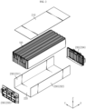
- FIG. 1 is an assembled perspective view schematically showing a battery module according to an embodiment of the present disclosure
- FIG. 2 is an exploded perspective view showing the battery module of FIG. 1 .
- the battery module includes a cell assembly 100 and a module case 200.
- the cell assembly 100 may include at least one battery cell.
- each battery cell may refer to a secondary battery.
- the secondary battery may include an electrode assembly, an electrolyte and a battery case.
- the battery cell provided in the cell assembly 100 may be a pouch-type secondary battery.
- other types of secondary batteries such as a cylindrical battery or a rectangular battery, may also be employed in the cell assembly 100 of the present disclosure.
- a plurality of secondary batteries may form the cell assembly 100 in a stacked form.
- the plurality of secondary batteries may be stacked so as to be arranged in a horizontal direction (Y-axis direction in the drawing) while being erect in an upper and lower direction (Z-axis direction in the drawing), respectively.
- Each battery cell may include electrode leads, and the electrode leads may be located at both ends or at one end of each battery cell.
- a secondary battery in which the electrode leads protrude in both directions may be called a bidirectional cell, and a secondary battery in which the electrode leads protrude in one direction may be called a unidirectional cell.
- the present disclosure is not limited by the specific type or form of these secondary batteries, and various types of secondary batteries known at the time of filing of this application may be employed in the cell assembly 100 of the present disclosure.
- the module case 200 may include a top plate 210, a base plate 220 and a side plate 230, as shown in FIG. 2 .
- the module case 200 may define an inner space by these components, namely the top plate 210, the base plate 220, and the side plate 230.
- the top plate 210 may be disposed at the upper portion of the module case 200
- the base plate 220 may be disposed at the lower portion of the top plate 210 to be spaced apart from the top plate 210 by a predetermined distance.
- the side plate 230 may be disposed between the top plate 210 and the side plate 230 to connect top ends and bottoms thereof.
- the top plate 210, the base plate 220, and/or the side plate 230 may be configured in the form of a thin sheet, namely in a plate shape, but may be configured in a polyhedral shape with a thickness greater than a certain level, for example a rectangular parallelepiped shape.
- the side plate 230 may include a left plate 231, a right plate 232, a front plate 233 and a rear plate 234.
- the top plate 210, the base plate 220 and/or the side plate 230 may be entirely or partially made of a metal material. Also, at least some of them may be made of a plastic material.
- the top plate 210, the base plate 220, and the side plate 230 may be formed integrally with each other.
- the left plate 231 and the right plate 232 may be formed integrally with the base plate 220.
- the left plate 231, the right plate 232 and the base plate 220, which are integrated with each other may be referred to as U-frame due to their shape.
- the front plate 233 and the rear plate 234 may serve as end plates and be respectively coupled to the openings at front and rear ends of the U-frame.
- the top plate 210 may be coupled to the opening at the top end of the U-frame.
- the module case 200 may be configured in various other forms.
- the base plate 220 and the four side plates 230 may form a lower case in an integrated shape, namely in a box shape.
- the top plate 210 may be coupled to the opening at the top end of the box-shaped lower case.
- the top plate 210, the front plate 233, and the rear plate 234 may be coupled with the U-frame through laser welding or ultrasonic welding.
- the components of the module case 200 may be coupled to each other through a bolt fastening method or the like.
- the module case 200 may accommodate the cell assembly 100 in the inner space defined by the top plate 210, the base plate 220 and the side plate 230 as described above.
- the module case 200 may be configured to have different expansibility with respect to at least some of various components such as the top plate 210, the base plate 220, and the side plate 230.
- the top plate 210 may be configured to at least partially have high expansibility compared to other components, namely the base plate 220 and/or the side plate 230.
- the top plate 210 may be configured to include a material with a high expansion rate compared to other components of the module case 200.
- the base plate 220 and the side plate 230 may be made of an aluminum material
- the top plate 210 may be made of a material with better expansibility than the aluminum material, for example a material such as zinc.
- the base plate 220 and the side plate 230 may be made of an iron material
- the top plate 210 may be made of a material with better expansibility than the iron material, for example a material such as aluminum.
- good expansibility of the top plate 210 may mean that the volume of the top plate 210 itself is expanded, or may also mean that the volume of the space located below the top plate 210 is expanded due to deformation or stretching of the top plate 210.
- a portion with high expansibility, particularly the top plate 210 may expand.
- gas and/or heat may be accumulated in the inner space of the module case 200 whose volume is increased by the expansion, it may act as a buffer for gas and/or heat. This will be described in more detail with reference to FIGS. 3 and 4 further.
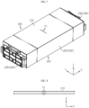
- FIGS. 3 and 4 are a perspective view and a cross-sectional view schematically showing that the top plate 210 is expanded in the battery module according to an embodiment of the present disclosure.
- FIG. 4 shows a cross-sectional shape, taken along line A1-A1' of FIG. 3 .
- the top plate 210 when gas and/or heat is generated and discharged from the cell assembly 100, since the top plate 210 is configured to expand well compared to other parts in the module case 200, the top plate 210 may be inflated first.
- the top plate 210 may be curved upward due to the expansion by gas and/or heat. That is, the top plate 210 may be configured to be bent upward when the internal pressure and/or internal temperature of the module case 200 increases, while maintaining a flat state in a normal state.
- an expanded empty space may be formed inside the top plate 210, as indicated by B 1 in FIG. 4 .
- the empty space B1 formed as described above the gas and/or heat discharged from the cell assembly 100 may be accumulated.
- the safety of the battery module may be further improved.
- the internal pressure of the battery module may increase, and the gas may accumulate in the inner space B 1 additionally provided due to the expansion of the top plate 210. Accordingly, the increase in internal pressure due to gas discharge may be alleviated, and the possibility of an explosion of the module due to gas may be reduced.
- the module case 200 may be formed such that the inner space is completely sealed. At this time, if the internal pressure of the battery module increases, the risk of explosion may be greater. However, according to this embodiment, the increase in internal pressure may be alleviated by the expansion of the inner space due to the deformation of the top plate 210. Therefore, the risk of explosion may be lowered.
- the module case 200 may be configured such that the inner space is not completely sealed.
- the front plate 233 and/or the rear plate 234 may be provided with a module terminal or a communication connector for connection with other external components.
- the gas or heat generated inside the module case 200 may be discharged to the outside of the module case 200 through a gap existing in the module terminal or the communication connector itself or its periphery.
- the gas or heat is discharged at an excessively high speed or amount through the gap, other battery modules, other devices nearby, and the driver or occupants may be damaged.
- gas or heat is generated at an amount or rate that exceeds the level that can be discharged through the corresponding gap, the possibility of explosion or fire of the battery module may still exist.
- the expanded space provided at the inside of the top plate 210 serves as a buffer, so that it is possible to significantly reduce the possibility of explosion.
- the gas discharged from the cell assembly 100 may be relatively high temperature, and, according to this embodiment, since the volume expansion occurs in the space where the gas is located, the temperature of the gas may be lowered. Accordingly, it is possible to reduce the problem that heat is transferred from the battery module in which a thermal event has occurred to other battery modules or other devices nearby. Moreover, in the case where the battery module is included in a battery pack for a vehicle, a person such as a driver or occupant may exist around the battery module, such as above the battery module. However, according to this embodiment, it is possible to prevent or reduce heat transfer toward the driver or occupant.
- the battery pack for a vehicle may ensure the escape time of the driver or occupant to a certain level or above. Therefore, even in this aspect, it may be regarded that the safety of the battery module is further improved.
- the top plate 210 may have a different elastic modulus or different thermal expansion coefficient from other portions of the module case 200 in order to have higher expansibility than other portions of the module case 200.
- the top plate 210 may be configured to at least partially have a lower elastic modulus compared to the base plate 220 and/or side plate 230. That is, the top plate 210 may be formed of a material or shape that deforms better than the base plate 220 or the side plate 230, even the same force is applied.
- the base plate 220 and the side plate 230 are made of a material such as titanium or SUS (Stainless Steel)
- the top plate 210 may be made of a material with a lower elastic modulus, for example a material such as aluminum.
- the top plate 210 may be deformed to be curved upward as shown in FIGS. 3 and 4 .
- the gas may be accumulated in the inner space formed due to the deformation of the top plate 210. Accordingly, a problem caused by a large and rapid increase in pressure inside the module case 200, for example explosion of the battery module, may be prevented.
- the top plate 210 may be configured to at least partially have a higher thermal expansion coefficient compared to the base plate 220 and/or side plate 230.
- the top plate 210 may be made of an aluminum material, an aluminum-zinc alloy material, or a zinc material having a higher thermal expansion coefficient.
- the top plate 210 when heat is generated or a high-temperature gas is generated and discharged from the cell assembly 100, the top plate 210 may be deformed to be curved upward as shown in FIGS. 3 and 4 by the heat. In addition, since the volume of the inner space B1 of the top plate 210 is expanded due to this deformation, the temperature of the heat may be lowered. Accordingly, it is possible to prevent a problem that may occur due to a rapid increase in heat inside the module case 200, such as thermal runaway propagation or fire.
- FIG. 5 is a perspective view schematically showing a battery module according to another embodiment of the present disclosure.
- any feature identical or similar to that of the former embodiment will not be described in detail, and a feature different therefrom will be described in detail.
- a venting hole may be formed in the module case 200, as indicated by H.
- the venting hole H may be formed in the left plate 231 and the right plate 232 of the module case 200, respectively.
- the venting hole H may be configured to penetrate the inner space and outer space of the module case 200. In this case, it may be regarded that the module case 200 is configured such that the inner space is not sealed.
- the generated venting gas may be discharged to the outside through the venting hole H.
- high heat or pressure may be applied to other surrounding components, such as other battery modules, pack housings, and BMS (Battery Management System) by the discharged gas.
- the applied heat or pressure may cause thermal runaway propagation, damage to surrounding components, or fire.
- the gas ejection rate of the cell assembly 100 is greater than the level that the venting hole H can discharge, an explosion or fire of the corresponding battery module may occur.
- the inner space of the top plate 210 is expanded by gas and/or heat to serve as a buffer, it is possible to reduce the risk of such an explosion or fire. Moreover, according to this embodiment, since the gas discharge rate per hour may be lowered, the temperature of the portion where the gas is discharged may be lowered. In addition, according to this embodiment, it is possible to delay the discharge of the high-temperature gas or flame through the venting hole H, so that the time for the driver or the like to escape may be additionally secured.
- FIG. 6 is a perspective view schematically showing a battery module according to still another embodiment of the present disclosure.
- the module case 200 may further include a module valve 240.
- the module valve 240 may be mounted in the venting hole H of the module case 200.
- the module valve 240 may seal the inner space of the module case 200 in a state of being mounted in the venting hole H.
- the module valve 240 may be configured to open when the temperature or pressure of the inner space of the module case 200 is in a certain level or above.
- the venting hole H may be formed in the top plate 210.
- the module valve 240 may be configured to be inserted into the venting hole H of the top plate 210. Therefore, in a normal state, the module valve 240 may close the venting hole H, so that the inner space of the module case 200 is sealed. However, when a certain level of gas, heat, or flame is generated from the cell assembly 100 and ejected into the module case 200, the module valve 240 may open the venting hole H without blocking any more.
- the module valve 240 may open the venting hole H in various ways when heat or gas is generated.
- the module valve 240 may open the venting hole H may be melted or deformed at a temperature of a certain level or above to open the venting hole H.
- the module valve 240 may be separated from the venting hole H to open the venting hole H when the pressure inside the module case 200 is in a certain level or above.
- the module valve 240 may be made of various materials such as plastic, aluminum, and/or SUS according to the opening method of the venting hole H or the specification of the cell assembly 100.
- the safety of the battery module may be further improved. That is, when gas, flame, or heat is generated from the cell assembly 100, since the venting hole H is closed by the module valve 240 at an initial stage, the inner space may be surely expanded due to the inflation (deformation) of the top plate 210. In addition, the gas, flame, heat, or the like at the initial stage may be accumulated in the expanded inner space, and its external discharge may be delayed. Accordingly, time for action, such as time for the driver to escape, may be secured at the initial stage of the thermal event.
- the venting hole H when the venting hole H is formed in the top plate 210 and the module valve 240 is provided in the venting hole H, gas, heat, flame, or the like may be discharged more stably.
- the gas, flame, and heat present inside the module case 200 may be mostly accumulated in the space increased due to the expansion of the top plate 210.
- the venting hole H is opened due to the deviation or deformation of the module valve 240, the gas, flame, heat, or the like may be discharged to the outside through the venting hole H of the top plate 210. Therefore, it is possible to minimize the influence of heat or gas energy accumulated in the inner space on other normal cells in the module case 200 or other components such as bus bars. Therefore, in this case, it is possible to more effectively prevent heat propagation between cells or damage to components.
- the venting hole may be configured to be opened by deformation (inflation) of the top plate 210. This will be described in more detail with reference to FIGS. 7 to 9 .
- FIG. 7 is a perspective view schematically showing a battery module according to still another embodiment of the present disclosure. Also, FIG. 8 is a cross-sectional view showing the C1 portion of the top plate 210 in FIG. 7 , and FIG. 9 is a cross-sectional view schematically showing the deformed state of the top plate 210 of FIG. 8 .
- the top plate 210 may be formed in a cut form like the portion indicated by C1. Moreover, the cut portion of the top plate 210 may be configured in a closed form in a normal state, namely in a state where there is no deformation by heat or gas. In addition, even if the top plate 210 is slightly deformed, the cut portion may be continuously closed when the degree of deformation does not reach a certain level. Therefore, when gas or heat is generated from the cell assembly 100, as shown in FIG. 9 , the top plate 210 may be expanded and deformed to be curved upward.
- the cut portion may be widened, as indicated by the portion C2 of FIG. 9 .
- a venting hole H may be formed, so that the gas or heat accumulated in the lower portion of the top plate 210 may be discharged to the outside.
- the cut portion which is opened to serve as a venting hole when the top plate 210 is deformed, may be located on the top plate 210.
- the venting direction when gas or heat is discharged, the venting direction may be controlled, and the influence on other battery cells or components may be reduced.
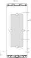
- FIG. 10 is a top view schematically showing a top plate 210 included in the battery module according to still another embodiment of the present disclosure.
- the top plate 210 may be configured to partially have different expansibility (strain).
- the top plate 210 may be configured such that materials with different expansibility exist at different positions.
- the portion indicated by T1 and the portion indicated by T2 in FIG. 10 may be made of different materials.
- the portions having different expansibility may be coupled in various ways, such as welding, bolting or bonding.
- the position and shape of the expansion and deformation may be more specifically controlled. For example, depending on the location or shape of an empty space that allows expansion at the upper portion of the battery module, or depending on the arrangement of components that may properly discharge heat accumulated under the top plate 210, such as a cooling device, or depending on the location where other battery modules are placed, the top plate 210 may be expanded and deformed in an appropriate shape.
- the top plate 210 may be configured such that the center portion has a higher expansibility than the rim portion.
- the center portion indicated by T1 and the rim portion indicated by T2 may be made of different materials, where the center portion may be made of a material with better expansibility than the rim portion. That is, in the top plate 210, the center portion indicated by T1 may be a high expansion portion that expands relatively large, and the rim portion indicated by T2 may be a low expansion portion that expands relatively small.
- the rim portion may be made of a material having poor expansibility than the center portion and good other characteristics.
- the top plate 210 may be welded to the side plate 230, and the portion of the top plate 210 welded to the side plate 230 may be referred to as a rim portion. Therefore, the rim portion may be made of a material having good weldability rather than expansibility.
- the high expansion portion indicated by T1 may be made of a zinc material having good expansibility
- the low expansion portion indicated by T2 may be made of an aluminum material having good weldability.
- the low expansion portion T2 of the top plate 210 may be made of the same material as the side plate 230.
- the side plate 230 of the module case 200 is made of iron or aluminum material
- the low expansion portion T2 of the top plate 210 may also be made of iron or aluminum material in the same way.
- the top plate 210 may be configured to have both expansibility and weldability. That is, the high expansion portion T1 located in the center portion of the top plate 210 may be deformed upward to secure the inner space when internal pressure or temperature increases, and the low expansion portion T2 located in the rim portion of the top plate 210 may not be deformed greatly even when internal pressure or temperature increases, and may stably maintain the welding condition while securing excellent weldability with the top end of the side plate 230.
- a venting hole H may be formed in the top plate 210 around the high expansion portion T1.
- the venting hole H may be configured to penetrate the inside and outside of the module case 200 and serve to discharge the internal gas to the outside.
- the venting hole H may be formed in the boundary portion between the center portion and the rim portion.
- a plurality of venting holes H may be formed around the high expansion portion T1 of the top plate 210.
- the venting holes H are formed along the outer line of the portion of the top plate 210 where the expansion occurs greatly, when the gas and/or heat accommodated in the inner space of the center portion of the top plate 210 is discharged to the outside through the venting hole H, it is possible to prevent the gas and/or heat from applying physical force or heat to other battery cells, bus bars, and connection components of electrode leads.
- the top plate 210 may further include a module valve 240 for opening and closing each venting hole H.
- the top plate 210 may be configured to have expansibility asymmetrically. This will be described in more detail with reference to FIG. 11 .
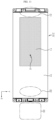
- FIG. 11 is a top view schematically showing a top plate 210 included in the battery module according to still another embodiment of the present disclosure.
- the top plate 210 includes a high expansion portion T1 and a low expansion portion T2, and the high expansion portion T1 may be formed in an asymmetrical shape and/or position.
- the high expansion portion T1 may be configured to be tilted in a specific direction, rather than being located precisely in the center of the top plate 210.
- the center point of the top plate 210 is a portion marked with O
- the high expansion portion T1 may be provided at a position biased in the -X-axis direction with respect to the center point.
- the processes such as expansion of the top plate 210 or accumulation or discharge of gas and heat may be performed effectively or stably.
- these processes may be stably performed according to the shape and arrangement of other components included inside or outside the battery module, such as battery cells, venting holes, and other battery modules.
- the high expansion portion T1 may be located in the portion of the top plate 210 that is biased closer to the venting hole H.
- the high expansion portion T1 may be located relatively far from the portion D2. Therefore, when gas or heat is accumulated and discharged, it is possible to prevent these components from being damaged by the gas or heat.
- the high expansion portion T1 may be located relatively far from the portion D3. Therefore, when gas or heat is accumulated and discharged, it is possible to prevent heat propagation to another battery module or control device by the gas or heat.
- FIG. 12 is a perspective view showing a coupled portion in a module case 200 of the battery module according to an embodiment of the present disclosure.
- the module case 200 includes a top plate 210, a base plate 220 and a side plate 230, and these components may be coupled to each other to seal the inner space.
- the ends of the top plate 210 and the side plate 230, and/or the ends of the side plate 230 and the base plate 220 may be coupled to each other, as indicated by F1 to F4 and F1' to F2'.
- the top plate 210 and the side plate 230, and/or the side plate 230 and the base plate 220 may be connected to each other by welding.
- the inner space may be additionally secured by the expansion of the top plate 210 to a certain level, thereby preventing the gas or flame from being discharged to the outside.
- the internal pressure of the module case 200 exceeds a certain level, at least a part of the coupled portion between the top plate 210 and the side plate 230 and/or between the side plate 230 and the base plate 220 may be destroyed.
- FIG. 12 when the portions indicated by F1 to F4 and F1' to F2' are welded, at least a part of these welded portions may be damaged, and the gas or flame may be discharged to the outside through the damaged part.
- various coupled portions between the top plate 210 and the side plate 230 and/or between the side plate 230 and the base plate 220 may be configured to have different coupling forces (welding forces).
- the module case 200 may be configured such that welding of the portion indicated by F3 is intentionally weaker than other portions, among the portions indicated by F1 to F4 and F1' to F2'.
- the portion indicated by F3 may be damaged first. Therefore, since the gas, flame, heat, or the like may be discharged through the corresponding portion, it is possible to control the discharging direction.
- a battery pack according to the present disclosure may include one or more battery modules according to the present disclosure described above.
- the battery pack according to the present disclosure may further include various components other than these battery modules, for example components of the battery pack known at the time of filing of this application, such as a BMS or a bus bar, a pack case, a relay, and a current sensor.
- the battery module according to the present disclosure may be applied to a vehicle such as an electric vehicle or a hybrid electric vehicle. That is, the vehicle according to the present disclosure may include the battery module according to the present disclosure or the battery pack according to the present disclosure. In addition, the vehicle according to the present disclosure may further include various other components included in a vehicle in addition to the battery module or the battery pack. For example, the vehicle according to the present disclosure may further include a vehicle body, a motor, a control device such as an electronic control unit (ECU), and the like in addition to the battery module according to the present disclosure.
- ECU electroniceeee control unit
Landscapes
- Chemical & Material Sciences (AREA)
- Chemical Kinetics & Catalysis (AREA)
- Electrochemistry (AREA)
- General Chemical & Material Sciences (AREA)
- Engineering & Computer Science (AREA)
- Aviation & Aerospace Engineering (AREA)
- Mechanical Engineering (AREA)
- Transportation (AREA)
- Sustainable Energy (AREA)
- Power Engineering (AREA)
- Sustainable Development (AREA)
- Life Sciences & Earth Sciences (AREA)
- Manufacturing & Machinery (AREA)
- Battery Mounting, Suspending (AREA)
- Gas Exhaust Devices For Batteries (AREA)
- Combustion & Propulsion (AREA)
Applications Claiming Priority (2)
| Application Number | Priority Date | Filing Date | Title |
|---|---|---|---|
| KR1020210090553A KR102940431B1 (ko) | 2021-07-09 | 2021-07-09 | 안전성이 강화된 배터리 모듈 |
| PCT/KR2022/009997 WO2023282712A1 (ko) | 2021-07-09 | 2022-07-08 | 안전성이 강화된 배터리 모듈 |
Publications (3)
| Publication Number | Publication Date |
|---|---|
| EP4354617A1 true EP4354617A1 (de) | 2024-04-17 |
| EP4354617A4 EP4354617A4 (de) | 2024-09-04 |
| EP4354617B1 EP4354617B1 (de) | 2026-02-18 |
Family
ID=84801818
Family Applications (1)
| Application Number | Title | Priority Date | Filing Date |
|---|---|---|---|
| EP22838063.0A Active EP4354617B1 (de) | 2021-07-09 | 2022-07-08 | Batteriemodul mit verstärkter sicherheit |
Country Status (6)
| Country | Link |
|---|---|
| US (1) | US20250329862A1 (de) |
| EP (1) | EP4354617B1 (de) |
| JP (1) | JP7842131B2 (de) |
| KR (2) | KR102940431B1 (de) |
| CN (1) | CN117616624A (de) |
| WO (1) | WO2023282712A1 (de) |
Families Citing this family (8)
| Publication number | Priority date | Publication date | Assignee | Title |
|---|---|---|---|---|
| KR102804712B1 (ko) * | 2023-04-05 | 2025-05-07 | 삼성에스디아이 주식회사 | 이차전지 팩 |
| WO2024253014A1 (ja) * | 2023-06-07 | 2024-12-12 | 株式会社Aescジャパン | 電池モジュール |
| KR20250007297A (ko) * | 2023-07-05 | 2025-01-14 | 주식회사 엘지에너지솔루션 | 배터리 팩 및 이를 포함하는 자동차 |
| KR102820682B1 (ko) * | 2023-07-12 | 2025-06-12 | 주식회사 엘지에너지솔루션 | 배터리 팩 |
| EP4668449A1 (de) * | 2023-09-08 | 2025-12-24 | LG Energy Solution, Ltd. | Batteriepack |
| KR102870479B1 (ko) * | 2023-09-08 | 2025-10-15 | 주식회사 엘지에너지솔루션 | 배터리 팩 |
| WO2025136054A1 (ko) * | 2023-12-22 | 2025-06-26 | 주식회사 엘지에너지솔루션 | 배터리 팩 및 이를 포함하는 자동차 |
| KR20250148210A (ko) * | 2024-04-05 | 2025-10-14 | 주식회사 엘지에너지솔루션 | 배터리 팩 및 이를 포함하는 자동차 |
Family Cites Families (16)
| Publication number | Priority date | Publication date | Assignee | Title |
|---|---|---|---|---|
| JP2006128043A (ja) * | 2004-11-01 | 2006-05-18 | Sanyo Electric Co Ltd | 密閉型電池 |
| JP2010232330A (ja) | 2009-03-26 | 2010-10-14 | Autech Japan Inc | 強電体のケース構造 |
| KR101191657B1 (ko) * | 2010-07-19 | 2012-10-17 | 에스비리모티브 주식회사 | 전지 모듈 |
| JP2012228946A (ja) | 2011-04-26 | 2012-11-22 | Suzuki Motor Corp | 車両のバッテリシステム |
| DE102014206868B4 (de) * | 2014-04-09 | 2023-08-24 | Frederic Dietze | Gehäuse für eine Energiespeichervorrichtung, Energiespeichervorrichtung mit einem derartigen Gehäuse und Verfahren zu deren Herstellung |
| KR102065104B1 (ko) * | 2015-09-10 | 2020-01-10 | 주식회사 엘지화학 | 배터리 모듈 |
| WO2017052296A1 (ko) | 2015-09-24 | 2017-03-30 | 주식회사 엘지화학 | 배터리 모듈 |
| KR101954043B1 (ko) | 2015-10-05 | 2019-03-04 | 닛산 지도우샤 가부시키가이샤 | 배터리 팩의 압력 개방 기구 |
| DE102016110330A1 (de) | 2016-06-03 | 2017-12-07 | Thyssenkrupp Ag | Gehäuse für eine Fahrzeugbatterie sowie Verfahren zur Herstellung eines solchen Gehäuses |
| WO2018012224A1 (ja) | 2016-07-11 | 2018-01-18 | パナソニックIpマネジメント株式会社 | 電池モジュール |
| KR102270269B1 (ko) | 2018-01-17 | 2021-06-28 | 주식회사 엘지에너지솔루션 | 리유즈, 리사이클 내지 리웍이 용이한 접착 구조를 갖는 배터리 모듈 하우징 및 이를 포함하는 배터리 모듈 |
| KR102716908B1 (ko) | 2019-03-21 | 2024-10-11 | 주식회사 엘지에너지솔루션 | 박판 타입의 모듈 하우징을 갖는 배터리 모듈과 이를 포함하는 배터리 팩 |
| CN112582744B (zh) * | 2019-09-30 | 2021-11-12 | 比亚迪股份有限公司 | 一种电池模组封装结构、电池模组以及汽车 |
| KR102464825B1 (ko) | 2019-10-10 | 2022-11-07 | 주식회사 엘지에너지솔루션 | 전지 모듈 및 이를 포함하는 전지팩 |
| CN112838333A (zh) * | 2019-11-22 | 2021-05-25 | 比亚迪股份有限公司 | 一种电池、电池模组、电池包和汽车 |
| CN111189526A (zh) | 2020-01-09 | 2020-05-22 | 哈尔滨工程大学 | 一种特定船坞中船舶水下辐射噪声测量装置及测量方法 |
-
2021
- 2021-07-09 KR KR1020210090553A patent/KR102940431B1/ko active Active
-
2022
- 2022-07-08 EP EP22838063.0A patent/EP4354617B1/de active Active
- 2022-07-08 CN CN202280048425.2A patent/CN117616624A/zh active Pending
- 2022-07-08 US US18/577,568 patent/US20250329862A1/en active Pending
- 2022-07-08 WO PCT/KR2022/009997 patent/WO2023282712A1/ko not_active Ceased
- 2022-07-08 JP JP2023579597A patent/JP7842131B2/ja active Active
-
2026
- 2026-03-10 KR KR1020260043154A patent/KR20260048500A/ko active Pending
Also Published As
| Publication number | Publication date |
|---|---|
| KR102940431B1 (ko) | 2026-03-16 |
| WO2023282712A1 (ko) | 2023-01-12 |
| US20250329862A1 (en) | 2025-10-23 |
| KR20230009760A (ko) | 2023-01-17 |
| JP7842131B2 (ja) | 2026-04-07 |
| EP4354617A4 (de) | 2024-09-04 |
| CN117616624A (zh) | 2024-02-27 |
| JP2024524315A (ja) | 2024-07-05 |
| EP4354617B1 (de) | 2026-02-18 |
| KR20260048500A (ko) | 2026-04-10 |
Similar Documents
| Publication | Publication Date | Title |
|---|---|---|
| EP4354617A1 (de) | Batteriemodul mit verstärkter sicherheit | |
| EP3512008A1 (de) | Batteriemodul sowie batteriepack und fahrzeug damit | |
| KR102713991B1 (ko) | 안전성이 향상된 배터리 모듈 | |
| EP4391190A1 (de) | Batteriepack und fahrzeug damit | |
| EP4383432A1 (de) | Batteriepack und fahrzeug damit | |
| EP4345999A1 (de) | Batteriemodul mit verbesserter sicherheit und montage | |
| EP4167363B1 (de) | Batteriemodul, batteriepack und fahrzeug damit | |
| EP4239768A1 (de) | Batteriemodul mit verbesserter sicherheit | |
| EP4274014B1 (de) | Batteriemodul und batteriepack mit verstärkter sicherheit | |
| US20250158215A1 (en) | Battery module with reinforced safety | |
| US20230318132A1 (en) | Battery module with reinforced safety | |
| KR20250007973A (ko) | 배터리 모듈 | |
| EP4318774B1 (de) | Batteriepack und fahrzeug damit | |
| EP4576379A1 (de) | Batteriemodul | |
| EP4287389A1 (de) | Batteriemodul mit verstärkter sicherheit | |
| EP4579939A1 (de) | Batteriemodul | |
| EP4675817A1 (de) | Batteriepack | |
| EP4668449A1 (de) | Batteriepack | |
| EP4362195A1 (de) | Batteriezelle, batteriemodul, batteriepack und fahrzeug damit | |
| EP4576378A1 (de) | Batterieeinheitsstruktur und fahrzeug damit | |
| EP4712243A1 (de) | Batteriepack | |
| EP4708497A2 (de) | Batteriepack und energiespeichersystem damit | |
| EP4738584A1 (de) | Batteriepack | |
| KR20240074454A (ko) | 안전성이 강화된 배터리 모듈 | |
| KR20250049106A (ko) | 배터리 셀 |
Legal Events
| Date | Code | Title | Description |
|---|---|---|---|
| STAA | Information on the status of an ep patent application or granted ep patent |
Free format text: STATUS: THE INTERNATIONAL PUBLICATION HAS BEEN MADE |
|
| PUAI | Public reference made under article 153(3) epc to a published international application that has entered the european phase |
Free format text: ORIGINAL CODE: 0009012 |
|
| STAA | Information on the status of an ep patent application or granted ep patent |
Free format text: STATUS: REQUEST FOR EXAMINATION WAS MADE |
|
| 17P | Request for examination filed |
Effective date: 20240111 |
|
| AK | Designated contracting states |
Kind code of ref document: A1 Designated state(s): AL AT BE BG CH CY CZ DE DK EE ES FI FR GB GR HR HU IE IS IT LI LT LU LV MC MK MT NL NO PL PT RO RS SE SI SK SM TR |
|
| A4 | Supplementary search report drawn up and despatched |
Effective date: 20240806 |
|
| RIC1 | Information provided on ipc code assigned before grant |
Ipc: H01M 50/249 20210101ALI20240731BHEP Ipc: H01M 50/375 20210101ALI20240731BHEP Ipc: H01M 50/342 20210101ALI20240731BHEP Ipc: H01M 50/383 20210101ALI20240731BHEP Ipc: H01M 50/233 20210101AFI20240731BHEP |
|
| DAV | Request for validation of the european patent (deleted) | ||
| DAX | Request for extension of the european patent (deleted) | ||
| STAA | Information on the status of an ep patent application or granted ep patent |
Free format text: STATUS: EXAMINATION IS IN PROGRESS |
|
| 17Q | First examination report despatched |
Effective date: 20250409 |
|
| REG | Reference to a national code |
Ref country code: DE Ref legal event code: R079 Free format text: PREVIOUS MAIN CLASS: H01M0050233000 Ipc: H01M0010625000 Ref country code: DE Ref legal event code: R079 Ref document number: 602022030807 Country of ref document: DE Free format text: PREVIOUS MAIN CLASS: H01M0050233000 Ipc: H01M0010625000 |
|
| GRAP | Despatch of communication of intention to grant a patent |
Free format text: ORIGINAL CODE: EPIDOSNIGR1 |
|
| STAA | Information on the status of an ep patent application or granted ep patent |
Free format text: STATUS: GRANT OF PATENT IS INTENDED |
|
| RIC1 | Information provided on ipc code assigned before grant |
Ipc: H01M 10/625 20140101AFI20250814BHEP Ipc: H01M 50/20 20210101ALI20250814BHEP Ipc: H01M 50/209 20210101ALI20250814BHEP Ipc: H01M 50/233 20210101ALI20250814BHEP Ipc: H01M 50/249 20210101ALI20250814BHEP Ipc: H01M 50/342 20210101ALI20250814BHEP Ipc: H01M 50/383 20210101ALI20250814BHEP Ipc: H01M 50/375 20210101ALI20250814BHEP |
|
| INTG | Intention to grant announced |
Effective date: 20250916 |
|
| GRAS | Grant fee paid |
Free format text: ORIGINAL CODE: EPIDOSNIGR3 |
|
| GRAA | (expected) grant |
Free format text: ORIGINAL CODE: 0009210 |
|
| STAA | Information on the status of an ep patent application or granted ep patent |
Free format text: STATUS: THE PATENT HAS BEEN GRANTED |
|
| AK | Designated contracting states |
Kind code of ref document: B1 Designated state(s): AL AT BE BG CH CY CZ DE DK EE ES FI FR GB GR HR HU IE IS IT LI LT LU LV MC MK MT NL NO PL PT RO RS SE SI SK SM TR |
|
| REG | Reference to a national code |
Ref country code: CH Ref legal event code: F10 Free format text: ST27 STATUS EVENT CODE: U-0-0-F10-F00 (AS PROVIDED BY THE NATIONAL OFFICE) Effective date: 20260218 Ref country code: GB Ref legal event code: FG4D |
|
| REG | Reference to a national code |
Ref country code: IE Ref legal event code: FG4D |
|
| REG | Reference to a national code |
Ref country code: DE Ref legal event code: R096 Ref document number: 602022030807 Country of ref document: DE |
|
| P01 | Opt-out of the competence of the unified patent court (upc) registered |
Free format text: CASE NUMBER: UPC_APP_0005010_4354617/2026 Effective date: 20260211 |