EP4354647A1 - Batteriezelle - Google Patents
Batteriezelle Download PDFInfo
- Publication number
- EP4354647A1 EP4354647A1 EP22823307.8A EP22823307A EP4354647A1 EP 4354647 A1 EP4354647 A1 EP 4354647A1 EP 22823307 A EP22823307 A EP 22823307A EP 4354647 A1 EP4354647 A1 EP 4354647A1
- Authority
- EP
- European Patent Office
- Prior art keywords
- cell
- connecting portion
- side push
- pole core
- lower insulating
- Prior art date
- Legal status (The legal status is an assumption and is not a legal conclusion. Google has not performed a legal analysis and makes no representation as to the accuracy of the status listed.)
- Pending
Links
Images



Classifications
-
- H—ELECTRICITY
- H01—ELECTRIC ELEMENTS
- H01M—PROCESSES OR MEANS, e.g. BATTERIES, FOR THE DIRECT CONVERSION OF CHEMICAL ENERGY INTO ELECTRICAL ENERGY
- H01M50/00—Constructional details or processes of manufacture of the non-active parts of electrochemical cells other than fuel cells, e.g. hybrid cells
- H01M50/10—Primary casings; Jackets or wrappings
- H01M50/102—Primary casings; Jackets or wrappings characterised by their shape or physical structure
- H01M50/107—Primary casings; Jackets or wrappings characterised by their shape or physical structure having curved cross-section, e.g. round or elliptic
-
- H—ELECTRICITY
- H01—ELECTRIC ELEMENTS
- H01M—PROCESSES OR MEANS, e.g. BATTERIES, FOR THE DIRECT CONVERSION OF CHEMICAL ENERGY INTO ELECTRICAL ENERGY
- H01M50/00—Constructional details or processes of manufacture of the non-active parts of electrochemical cells other than fuel cells, e.g. hybrid cells
- H01M50/50—Current conducting connections for cells or batteries
- H01M50/572—Means for preventing undesired use or discharge
- H01M50/584—Means for preventing undesired use or discharge for preventing incorrect connections inside or outside the batteries
- H01M50/59—Means for preventing undesired use or discharge for preventing incorrect connections inside or outside the batteries characterised by the protection means
- H01M50/593—Spacers; Insulating plates
-
- H—ELECTRICITY
- H01—ELECTRIC ELEMENTS
- H01M—PROCESSES OR MEANS, e.g. BATTERIES, FOR THE DIRECT CONVERSION OF CHEMICAL ENERGY INTO ELECTRICAL ENERGY
- H01M50/00—Constructional details or processes of manufacture of the non-active parts of electrochemical cells other than fuel cells, e.g. hybrid cells
- H01M50/10—Primary casings; Jackets or wrappings
- H01M50/172—Arrangements of electric connectors penetrating the casing
- H01M50/174—Arrangements of electric connectors penetrating the casing adapted for the shape of the cells
- H01M50/176—Arrangements of electric connectors penetrating the casing adapted for the shape of the cells for prismatic or rectangular cells
-
- H—ELECTRICITY
- H01—ELECTRIC ELEMENTS
- H01M—PROCESSES OR MEANS, e.g. BATTERIES, FOR THE DIRECT CONVERSION OF CHEMICAL ENERGY INTO ELECTRICAL ENERGY
- H01M50/00—Constructional details or processes of manufacture of the non-active parts of electrochemical cells other than fuel cells, e.g. hybrid cells
- H01M50/50—Current conducting connections for cells or batteries
- H01M50/531—Electrode connections inside a battery casing
- H01M50/533—Electrode connections inside a battery casing characterised by the shape of the leads or tabs
-
- H—ELECTRICITY
- H01—ELECTRIC ELEMENTS
- H01M—PROCESSES OR MEANS, e.g. BATTERIES, FOR THE DIRECT CONVERSION OF CHEMICAL ENERGY INTO ELECTRICAL ENERGY
- H01M50/00—Constructional details or processes of manufacture of the non-active parts of electrochemical cells other than fuel cells, e.g. hybrid cells
- H01M50/50—Current conducting connections for cells or batteries
- H01M50/543—Terminals
- H01M50/547—Terminals characterised by the disposition of the terminals on the cells
- H01M50/55—Terminals characterised by the disposition of the terminals on the cells on the same side of the cell
-
- H—ELECTRICITY
- H01—ELECTRIC ELEMENTS
- H01M—PROCESSES OR MEANS, e.g. BATTERIES, FOR THE DIRECT CONVERSION OF CHEMICAL ENERGY INTO ELECTRICAL ENERGY
- H01M50/00—Constructional details or processes of manufacture of the non-active parts of electrochemical cells other than fuel cells, e.g. hybrid cells
- H01M50/50—Current conducting connections for cells or batteries
- H01M50/543—Terminals
- H01M50/552—Terminals characterised by their shape
- H01M50/553—Terminals adapted for prismatic, pouch or rectangular cells
-
- H—ELECTRICITY
- H01—ELECTRIC ELEMENTS
- H01M—PROCESSES OR MEANS, e.g. BATTERIES, FOR THE DIRECT CONVERSION OF CHEMICAL ENERGY INTO ELECTRICAL ENERGY
- H01M50/00—Constructional details or processes of manufacture of the non-active parts of electrochemical cells other than fuel cells, e.g. hybrid cells
- H01M50/50—Current conducting connections for cells or batteries
- H01M50/543—Terminals
- H01M50/552—Terminals characterised by their shape
- H01M50/559—Terminals adapted for cells having curved cross-section, e.g. round, elliptic or button cells
-
- H—ELECTRICITY
- H01—ELECTRIC ELEMENTS
- H01M—PROCESSES OR MEANS, e.g. BATTERIES, FOR THE DIRECT CONVERSION OF CHEMICAL ENERGY INTO ELECTRICAL ENERGY
- H01M50/00—Constructional details or processes of manufacture of the non-active parts of electrochemical cells other than fuel cells, e.g. hybrid cells
- H01M50/50—Current conducting connections for cells or batteries
- H01M50/572—Means for preventing undesired use or discharge
- H01M50/574—Devices or arrangements for the interruption of current
- H01M50/583—Devices or arrangements for the interruption of current in response to current, e.g. fuses
-
- Y—GENERAL TAGGING OF NEW TECHNOLOGICAL DEVELOPMENTS; GENERAL TAGGING OF CROSS-SECTIONAL TECHNOLOGIES SPANNING OVER SEVERAL SECTIONS OF THE IPC; TECHNICAL SUBJECTS COVERED BY FORMER USPC CROSS-REFERENCE ART COLLECTIONS [XRACs] AND DIGESTS
- Y02—TECHNOLOGIES OR APPLICATIONS FOR MITIGATION OR ADAPTATION AGAINST CLIMATE CHANGE
- Y02E—REDUCTION OF GREENHOUSE GAS [GHG] EMISSIONS, RELATED TO ENERGY GENERATION, TRANSMISSION OR DISTRIBUTION
- Y02E60/00—Enabling technologies; Technologies with a potential or indirect contribution to GHG emissions mitigation
- Y02E60/10—Energy storage using batteries
Definitions
- the present application relates to the technical field of cells, for example, a cell.
- a cell of a battery As a main power source of an electric vehicle, a cell of a battery has become one of the key components of the electric vehicle.
- a plastic insulator is generally used for isolating a top cover from a post, thereby avoiding the conduction between the top cover and the post.
- the insulator includes an upper insulating plastic outside the cell and a lower insulating plastic inside the cell.
- the lower insulating plastic is provided with the post and other components.
- a tab drawn from a pole core needs to be welded to the post.
- a holder is disposed on the lower insulating plastic to isolate the pole core from the post and avoid the instability of the internal structure of the cell due to the excessively large assembly space of the lower insulating plastic inside the cell.
- the holder when the holder is assembled, the holder often directly covers the lower insulating plastic, and at the same time, the interference between the holder and the bent tab should be avoided.
- the assembly is thus complex. Moreover, the assembly tends to be improper, and the holder is connected unstably, making the internal structure of the cell unstable and making the pole core prone to shake, resulting in the reduction of the stability of the cell. Therefore, the safety performance of the cell cannot be guaranteed.
- the present application provides a cell, so as to make a holder easy to mount, improve the stability of a pole core fixed inside the cell, prevent the pole core from being displaced inside the cell, ensure the stability of the internal structure of the cell, and improve the safety performance of the cell.
- the cell includes an internal fixed structure of the cell, a pole core, a housing, and a top cover.
- the internal fixed structure of the cell includes a lower insulating plastic and a holder mounted on the lower insulating plastic.
- the lower insulating plastic is provided with an abutting surface.
- the abutting surface abuts against the pole core.
- the pole core is disposed in the housing and connected to a tab.
- the top cover is provided with a terminal.
- the top cover is connected to an end of the housing.
- the top cover is connected to the lower insulating plastic of the internal fixed structure of the cell.
- the abutting surface of the lower insulating plastic and the housing each abut against an outer wall of the pole core.
- first feature and the second feature may be in direct contact or be in contact via another feature between the two features instead of being in direct contact.
- first feature is described as “on”, “above” or “over” the second feature, the first feature is right on, above or over the second feature or the first feature is obliquely on, above or over the second feature, or the first feature is simply at a higher level than the second feature.
- the first feature When the first feature is described as “under”, “below”, or “underneath” the second feature, the first feature is right under, below, or underneath the second feature or the first feature is obliquely under, below, or underneath the second feature, or the first feature is simply at a lower level than the second feature.
- orientations or position relations indicated by terms such as “above”, “below”, “right” and the like are based on orientations or position relations shown in the drawings. These orientations or position relations are intended only to facilitate and simplify the operation, and not to indicate or imply that a device or element referred to must have such orientations or must be configured or operated in such orientations. Thus, these orientations or position relations are not to be construed as limiting the present application.
- the terms “first” and “second” are used only to distinguish between descriptions and have no special meaning.
- this embodiment provides a cell.
- the cell includes an internal fixed structure of the cell.
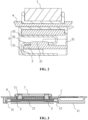
- the internal fixed structure of the cell includes a lower insulating plastic 1 and a holder 2.
- the lower insulating plastic 1 is provided with an abutting surface 11.
- the cell includes a housing 8 and a top cover 6.
- a pole core 9 is disposed in the housing 8.
- the abutting surface 11 abuts against the pole core 9.
- the pole core 9 is connected to a tab 5.
- the top cover 6 is provided with a terminal 7.
- the top cover 6 is connected to an end of the housing 8.
- the top cover 6 is connected to the lower insulating plastic 1 of the internal fixed structure of the cell.
- the abutting surface 11 of the lower insulating plastic 1 and the housing 8 each abut against an outer wall of the pole core 9.
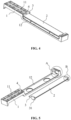
- the holder 2 is provided with a first side push connecting portion 3, the lower insulating plastic 1 is provided with a second side push connecting portion 4, and the holder 2 is mounted on the second side push connecting portion 4 by a side push along the thickness direction of the cell through the first side push connecting portion 3.
- the holder 2 is securely mounted on the lower insulating plastic 1 by a side push so that the holder 2 is very convenient to mount.
- the side push direction of the holder 2 is along the thickness direction of the cell, and the holder 2 does not interfere with the tab 5 so that the internal structure of the cell is stable, thereby preventing the pole core 9 from shaking and improving the stability of the cell and the safety performance of the cell.
- the housing 8 is made of aluminum.
- the housing 8 made of aluminum or aluminum alloy has many advantages, such as high capacity, light weight, high specific energy, high safety, and flexible production design.
- the lower insulating plastic 1 is provided with a groove
- the holder 2 has a plate-like structure and is mounted in the groove
- the first side push connecting portion 3 is disposed at edges on two sides of the holder 2
- the second side push connecting portion 4 includes a side push chute 41 opened on an inner wall of the groove of the lower insulating plastic 1
- a side push opening 411 is opened at an end of the side push chute 41
- the first side push connecting portion 3 slides into the side push chute 41 through the side push opening 411.
- fillet structures are disposed at edges of the holder 2 and the first side push connecting portion 3 facing the bottom of the chute, a fillet structure is disposed at an edge of the side push opening 411, and the smooth fillet structures have a guiding function so that the holder 2 drives the first side push connecting portion 3 to slide into the side push chute 41 more smoothly, thereby reducing the assembly difficulty and requirements for the machining accuracy.
- the holder 2 is securely assembled on the lower insulating plastic 1 by a side push, thereby increasing the structural strength of the lower insulating plastic 1.
- the orientation of the side push opening 411 and the length direction of the side push chute 41 are parallel to the thickness direction of the cell so that the side push of the holder 2 is smooth and more convenient.
- the first side push connecting portion 3 is provided with a slider 31, and the slider 31 is fixedly connected to the holder 2.
- the slider 31 is integrally formed with the holder 2.
- the second side push connecting portion 4 includes a corner missing structure 42 disposed on the holder 2, the corner missing structure 42 is connected to the side push opening 411, and when sliding into the side push chute 41, the first side push connecting portion 3 drives the slider 31 to just enter the corner missing structure 42.
- the cooperation between the corner missing structure 42 and the slider 31 improves the stability of the connection between the holder 2 and the lower insulating plastic 1.
- the corner missing structure 42 is provided so that it is more convenient for an operator to observe the position of the side push opening 411 from the missing corner of the corner missing structure 42, and the corner missing structure 42 has a function of guiding the mounting of the slider 31.
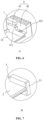
- a snap assembly is disposed between the slider 31 and the corner missing structure 42 and includes a snap slot 421 and a snap block 311 to which the snap slot 421 can be snap-fitted, one of the slider 31 or the corner missing structure 42 is provided with the snap slot 421, and the other one of the slider 31 or the corner missing structure 42 is provided with the snap block 311.
- the snap block 311 is fixedly connected to the slider 31, and the snap slot 421 is opened on an inner wall of the corner missing structure 42.
- the snap block 311 is snap-fitted in the snap groove 421, so as to prevent the first side push connecting portion 3 from sliding out of the side push chute 41, thereby ensuring a reinforcing effect.
- the holder 2 is securely mounted on the lower insulating plastic 1 by a side push, and the first side push connecting portion 3 slides into a first chute through the side push opening 411.
- the slider 31 enters the corner missing structure 42, an outer wall of the slider 31 abuts against the inner wall of the corner missing structure 42, and the snap block 311 is snap-fitted in the snap slot 421, so as to complete the installation and fixation of the holder 2.
- the side push installation manner makes the installation of the holder 2 very convenient.
- the side push direction is along the thickness direction of the cell, and the holder 2 does not interfere with the tab 5 so that the internal structure of the cell is stable, thereby avoiding the pole core 9 from shaking and improving the stability of the cell and the safety performance of the cell.
- the terminal 7 is provided with at least one post 71, and at least one of the at least one post 71 on the terminal 7 is welded to the tab 5.
- one terminal 7 is provided with two posts 71.
- the tab 5 includes a first connecting portion 51, a bend 52, and a second connecting portion 53, where the first connecting portion 51 is connected to the pole core 9, the bend 52 connects the first connecting portion 51 to the second connecting portion 53, the second connecting portion 53 is connected to the terminal 7, and when the first side push connecting portion 3 is mounted on the second side push connecting portion 4 by a side push, the holder 2 is inserted between the first connecting portion 51 and the bend 52.
- the tab 5 is provided with an empty slot 521 on the bend 52, and a weak overcurrent region is formed at an edge of the empty slot 521 of the tab 5.
- An overcurrent sectional area of the tab 5 is not greater than 15 mm 2 , and the weak overcurrent region acts as a protection device. When the current is too large, this region automatically fuses so as to protect the cell.
- a protrusion 21 is disposed on a side of the holder 2 facing the lower insulating plastic 1, and when the holder 2 is inserted between the first connecting portion 51 and the bend 52, the protrusion 21 can be inserted into the empty slot 521.
- the holder 2 plays a role of fixing the tab 5 through the protrusion 21.
- the holder 2 isolates the tab 5 from the pole core 9 and prevents the following: When the tab 5 acts as an external short-circuit protection device, the pole core 9 is damaged and a safety accident is caused.
- multiple empty slots 521 may be provided, multiple protrusions 21 may be provided correspondingly, and the empty slots 521 are in a one-to-one correspondence with the protrusions 21.
- the structural design of the internal fixed structure of the cell is not limited to the type of the battery, nor is it limited to whether battery terminals 7 are on the same side or different sides, and one or two internal fixed structures of the cell are provided.
- two internal fixed structures are provided, and the two internal fixed structures are disposed on different sides of the cell.
- the tab 5 includes a positive tab and a negative tab that are disposed on the different sides of the cell.
- the pole core 9 is disposed between the two internal fixed structures of the cell. A first end of the pole core 9 abuts against the abutting surface 11 of one lower insulating plastic 1, and a second end of the pole core 9 abuts against the abutting surface 11 of another lower insulating plastic 1.
- a bottom bracket 81 is fixedly disposed between the housing 8 and the pole core 9.
- two bottom brackets 81 are provided, and the two bottom brackets 81 are disposed on two sides of the pole core 9, each bottom bracket 81 is provided with multiple spaced openings 811, and the surface is glued for fixing.
- the bottom brackets 81 protect and support the pole core 9, and at the same time, the electrolyte and a pole piece of the pole core 9 are better wetted.
- one internal fixed structure of the cell may be provided, the tab 5 includes the positive tab and the negative tab that are disposed on the same side of the cell, positive and negative terminals 7 of the cell are on the same side of the cell, and the abutting surface 11 of the lower insulating plastic 1 mates with the housing 8 so as to abut the pole core 9 in the middle so that the pole core 9 is fixed and prevented from being displaced.
- the overcurrent area of the tab 5 required per unit of the length of the cell is S
- the width of the tab 5 is W
- the number of layers of the tab 5 is N
- S W ⁇ N
- the length of the cell is L
- the ratio of the overcurrent area S of the tab 5 to the length L of the cell is 2 to 25, such as 2, 6, 10, 20 and 25
- the length of the pole core 9 is l
- the ratio of the length l of the pole core 9 to the length L of the cell is 0.93 to 0.99, such as 0.93, 0.95, 0.97, 0.98 and 0.99.
- An implementation principle of the cell in this embodiment is described as follows: The internal fixed structure of the cell is provided, the holder 2 is mounted on the lower insulating plastic 1 by a side push, the abutting surface 11 of the lower insulating plastic 1 abuts against the pole core 9, and the pole core 9 mates with the housing 8 or the lower insulating plastic 1 on a different side so that the pole core 9 is fixed and prevented from being displaced; after the lower insulating plastic 1 is assembled, the holder 2 enters the lower plastic by a side push, the tab 5 is isolated from the pole core 9, the protrusion 21 on an upper surface of the holder 2 passes through the empty slot 521 in the weak overcurrent region of the tab 5 and plays a fixing role, and the following can be prevented: when the tab 5 acts as an external short-circuit protection device, the pole core 9 is damaged and a safety accident is caused.
Landscapes
- Chemical & Material Sciences (AREA)
- Chemical Kinetics & Catalysis (AREA)
- Electrochemistry (AREA)
- General Chemical & Material Sciences (AREA)
- Connection Of Batteries Or Terminals (AREA)
- Battery Mounting, Suspending (AREA)
- Coils Or Transformers For Communication (AREA)
Applications Claiming Priority (2)
| Application Number | Priority Date | Filing Date | Title |
|---|---|---|---|
| CN202210691303.7A CN114914591B (zh) | 2022-06-17 | 2022-06-17 | 一种电芯 |
| PCT/CN2022/104268 WO2023240717A1 (zh) | 2022-06-17 | 2022-07-07 | 电芯 |
Publications (2)
| Publication Number | Publication Date |
|---|---|
| EP4354647A1 true EP4354647A1 (de) | 2024-04-17 |
| EP4354647A4 EP4354647A4 (de) | 2024-10-23 |
Family
ID=82772604
Family Applications (1)
| Application Number | Title | Priority Date | Filing Date |
|---|---|---|---|
| EP22823307.8A Pending EP4354647A4 (de) | 2022-06-17 | 2022-07-07 | Batteriezelle |
Country Status (6)
| Country | Link |
|---|---|
| US (1) | US20240243451A1 (de) |
| EP (1) | EP4354647A4 (de) |
| KR (1) | KR20240140166A (de) |
| CN (1) | CN114914591B (de) |
| DE (1) | DE212022000420U1 (de) |
| WO (1) | WO2023240717A1 (de) |
Families Citing this family (2)
| Publication number | Priority date | Publication date | Assignee | Title |
|---|---|---|---|---|
| CN219106470U (zh) * | 2022-12-23 | 2023-05-30 | 湖北亿纬动力有限公司 | 电池绝缘件、顶盖组件及电池 |
| CN221447312U (zh) * | 2023-11-24 | 2024-07-30 | 兰钧新能源科技有限公司 | 一种电芯支架组件及电池 |
Family Cites Families (20)
| Publication number | Priority date | Publication date | Assignee | Title |
|---|---|---|---|---|
| KR20140139862A (ko) * | 2013-05-28 | 2014-12-08 | 삼성에스디아이 주식회사 | 배터리 팩 |
| KR102273643B1 (ko) * | 2014-10-07 | 2021-07-07 | 삼성에스디아이 주식회사 | 이차 전지 |
| US11245163B2 (en) * | 2016-08-01 | 2022-02-08 | Cps Technology Holdings Llc | Overcharge protection systems for prismatic lithium ion battery cells with biased packaging |
| CN108615830B (zh) * | 2016-12-12 | 2023-12-19 | 宁德时代新能源科技股份有限公司 | 动力电池顶盖结构及动力电池 |
| JP2020166955A (ja) * | 2019-03-28 | 2020-10-08 | 株式会社豊田自動織機 | 蓄電装置 |
| JP2020191236A (ja) * | 2019-05-22 | 2020-11-26 | 株式会社豊田自動織機 | 蓄電装置 |
| CN210156439U (zh) * | 2019-07-26 | 2020-03-17 | 湖北金泉新材料有限责任公司 | 绝缘组件、顶盖及电池 |
| CN110707244A (zh) * | 2019-10-18 | 2020-01-17 | 浙江天能能源科技股份有限公司 | 一种e-bike方形铝壳电池盖板 |
| CN111276732A (zh) * | 2020-03-30 | 2020-06-12 | 湖北亿纬动力有限公司 | 一种单体式电池和电池模组 |
| CN212625814U (zh) * | 2020-07-24 | 2021-02-26 | 蜂巢能源科技有限公司 | 用于动力电池的绝缘件 |
| CN111785901B (zh) * | 2020-07-24 | 2025-08-08 | 欣旺达动力科技股份有限公司 | 一种单体电池及一种动力电池 |
| CN212625815U (zh) * | 2020-07-24 | 2021-02-26 | 蜂巢能源科技有限公司 | 动力电池盖板及动力电池 |
| CN213340535U (zh) * | 2020-09-23 | 2021-06-01 | 湖北亿纬动力有限公司 | 电池顶盖组件、电池单体及电池包 |
| CN214043797U (zh) * | 2020-12-18 | 2021-08-24 | 湖北亿纬动力有限公司 | 电芯、电池模组及车辆 |
| CN213905519U (zh) * | 2020-12-18 | 2021-08-06 | 合肥国轩高科动力能源有限公司 | 方形电池 |
| CN214153028U (zh) * | 2020-12-31 | 2021-09-07 | 蜂巢能源科技有限公司 | 顶盖组件、电芯、电池和车辆 |
| CN214898620U (zh) * | 2021-04-02 | 2021-11-26 | 昆山宝创新能源科技有限公司 | 电芯组件 |
| CN216213745U (zh) * | 2021-10-18 | 2022-04-05 | 星恒电源股份有限公司 | 一种方形二次电池的顶盖及二次电池 |
| CN216624413U (zh) * | 2022-01-07 | 2022-05-27 | 合肥国轩高科动力能源有限公司 | 绝缘止动结构及电池 |
| CN218351643U (zh) * | 2022-07-22 | 2023-01-20 | 天津力神电池股份有限公司 | 一种具有新型封装结构的软包电池 |
-
2022
- 2022-06-17 CN CN202210691303.7A patent/CN114914591B/zh active Active
- 2022-07-07 US US18/013,930 patent/US20240243451A1/en active Pending
- 2022-07-07 EP EP22823307.8A patent/EP4354647A4/de active Pending
- 2022-07-07 KR KR1020247029328A patent/KR20240140166A/ko active Pending
- 2022-07-07 DE DE212022000420.5U patent/DE212022000420U1/de active Active
- 2022-07-07 WO PCT/CN2022/104268 patent/WO2023240717A1/zh not_active Ceased
Also Published As
| Publication number | Publication date |
|---|---|
| US20240243451A1 (en) | 2024-07-18 |
| CN114914591A (zh) | 2022-08-16 |
| WO2023240717A1 (zh) | 2023-12-21 |
| KR20240140166A (ko) | 2024-09-24 |
| CN114914591B (zh) | 2023-05-30 |
| EP4354647A4 (de) | 2024-10-23 |
| DE212022000420U1 (de) | 2025-02-28 |
Similar Documents
| Publication | Publication Date | Title |
|---|---|---|
| JP3702149B2 (ja) | 電源装置 | |
| EP4354647A1 (de) | Batteriezelle | |
| EP3641016B1 (de) | Batteriemodul und schutzanordnung dafür | |
| EP3907780A1 (de) | Klemmenschutzvorrichtung und batteriemodul | |
| EP1555703A3 (de) | Batteriepack | |
| JP7490056B2 (ja) | 電池モジュール、電池パック及び電池セルを電源として使用する装置 | |
| EP2741347A1 (de) | Spitzenkappenanordnung mit einem neuartigen aufbau | |
| JP2004031284A (ja) | パック電池 | |
| EP3920257A1 (de) | Batteriemodul, batteriepack und vorrichtung | |
| US12300841B2 (en) | Battery module | |
| CN213483886U (zh) | 一种电池包及车辆 | |
| JP2010129860A (ja) | 3方向の位置決め機構を備えた蓄電モジュール | |
| JP3505286B2 (ja) | パック電池 | |
| JP4488730B2 (ja) | 薄型バッテリーパック | |
| JP2023509716A (ja) | 二次電池、電池モジュール及び二次電池を電源として用いる装置 | |
| WO2006070731A1 (ja) | バッテリ、充電装置及び電子装置 | |
| EP3817089B1 (de) | Batteriemodul | |
| CN217656018U (zh) | 电池模组和储能设备 | |
| CN217788749U (zh) | 一种电芯内部固定结构及电芯 | |
| CN215816312U (zh) | 一种电池模组及电池包 | |
| CN216120654U (zh) | 一种电芯顶盖、电芯模组、动力电池包和车辆 | |
| CN211949970U (zh) | 一种遥控钥匙 | |
| CN216597865U (zh) | 一种电池模块、电池组及车辆 | |
| EP4376183A1 (de) | Batteriekastenkörper und batteriepack | |
| JP2001006636A (ja) | パック電池 |
Legal Events
| Date | Code | Title | Description |
|---|---|---|---|
| STAA | Information on the status of an ep patent application or granted ep patent |
Free format text: STATUS: UNKNOWN |
|
| STAA | Information on the status of an ep patent application or granted ep patent |
Free format text: STATUS: THE INTERNATIONAL PUBLICATION HAS BEEN MADE |
|
| PUAI | Public reference made under article 153(3) epc to a published international application that has entered the european phase |
Free format text: ORIGINAL CODE: 0009012 |
|
| STAA | Information on the status of an ep patent application or granted ep patent |
Free format text: STATUS: REQUEST FOR EXAMINATION WAS MADE |
|
| 17P | Request for examination filed |
Effective date: 20221223 |
|
| AK | Designated contracting states |
Kind code of ref document: A1 Designated state(s): AL AT BE BG CH CY CZ DE DK EE ES FI FR GB GR HR HU IE IS IT LI LT LU LV MC MK MT NL NO PL PT RO RS SE SI SK SM TR |
|
| A4 | Supplementary search report drawn up and despatched |
Effective date: 20240919 |
|
| RIC1 | Information provided on ipc code assigned before grant |
Ipc: H01M 50/55 20210101ALI20240913BHEP Ipc: H01M 50/107 20210101ALI20240913BHEP Ipc: H01M 50/176 20210101ALI20240913BHEP Ipc: H01M 50/593 20210101AFI20240913BHEP |
|
| DAV | Request for validation of the european patent (deleted) | ||
| DAX | Request for extension of the european patent (deleted) |