EP4354673A1 - Gehäuseanordnung für einen elektrischen verbinder - Google Patents
Gehäuseanordnung für einen elektrischen verbinder Download PDFInfo
- Publication number
- EP4354673A1 EP4354673A1 EP23202886.0A EP23202886A EP4354673A1 EP 4354673 A1 EP4354673 A1 EP 4354673A1 EP 23202886 A EP23202886 A EP 23202886A EP 4354673 A1 EP4354673 A1 EP 4354673A1
- Authority
- EP
- European Patent Office
- Prior art keywords
- locking lever
- groove
- housing assembly
- locked position
- housing body
- Prior art date
- Legal status (The legal status is an assumption and is not a legal conclusion. Google has not performed a legal analysis and makes no representation as to the accuracy of the status listed.)
- Granted
Links
Images




Classifications
-
- H—ELECTRICITY
- H01—ELECTRIC ELEMENTS
- H01R—ELECTRICALLY-CONDUCTIVE CONNECTIONS; STRUCTURAL ASSOCIATIONS OF A PLURALITY OF MUTUALLY-INSULATED ELECTRICAL CONNECTING ELEMENTS; COUPLING DEVICES; CURRENT COLLECTORS
- H01R13/00—Details of coupling devices of the kinds covered by groups H01R12/70 or H01R24/00 - H01R33/00
- H01R13/62—Means for facilitating engagement or disengagement of coupling parts or for holding them in engagement
- H01R13/629—Additional means for facilitating engagement or disengagement of coupling parts, e.g. aligning or guiding means, levers, gas pressure electrical locking indicators, manufacturing tolerances
- H01R13/62933—Comprising exclusively pivoting lever
- H01R13/62938—Pivoting lever comprising own camming means
-
- H—ELECTRICITY
- H01—ELECTRIC ELEMENTS
- H01R—ELECTRICALLY-CONDUCTIVE CONNECTIONS; STRUCTURAL ASSOCIATIONS OF A PLURALITY OF MUTUALLY-INSULATED ELECTRICAL CONNECTING ELEMENTS; COUPLING DEVICES; CURRENT COLLECTORS
- H01R13/00—Details of coupling devices of the kinds covered by groups H01R12/70 or H01R24/00 - H01R33/00
- H01R13/62—Means for facilitating engagement or disengagement of coupling parts or for holding them in engagement
- H01R13/629—Additional means for facilitating engagement or disengagement of coupling parts, e.g. aligning or guiding means, levers, gas pressure electrical locking indicators, manufacturing tolerances
- H01R13/62933—Comprising exclusively pivoting lever
- H01R13/62955—Pivoting lever comprising supplementary/additional locking means
-
- Y—GENERAL TAGGING OF NEW TECHNOLOGICAL DEVELOPMENTS; GENERAL TAGGING OF CROSS-SECTIONAL TECHNOLOGIES SPANNING OVER SEVERAL SECTIONS OF THE IPC; TECHNICAL SUBJECTS COVERED BY FORMER USPC CROSS-REFERENCE ART COLLECTIONS [XRACs] AND DIGESTS
- Y02—TECHNOLOGIES OR APPLICATIONS FOR MITIGATION OR ADAPTATION AGAINST CLIMATE CHANGE
- Y02T—CLIMATE CHANGE MITIGATION TECHNOLOGIES RELATED TO TRANSPORTATION
- Y02T10/00—Road transport of goods or passengers
- Y02T10/60—Other road transportation technologies with climate change mitigation effect
- Y02T10/70—Energy storage systems for electromobility, e.g. batteries
Definitions
- Embodiments of the present disclosure generally relate to a technical field of electrical connectors, and specifically, to a housing assembly for an electrical connector.
- the locking lever is pivotally connected to a connector housing, and the locking lever can pivot relative to the connector housing between a pre-locked position and a locked position.
- a lug structure is usually provided on an outer side surface of the connector housing and extends outwardly from the outer side surface, and a pivot action of the locking lever is constrained in a single direction by providing the lug structure on a pivoting path of the locking lever.
- provision of this lug structure can only constrain the pivot action of the locking lever in the single direction, and cannot achieve stable positioning of the locking lever, thus there is a risk of unwanted pivot action of the locking lever.
- provision of this lug structure increases the size of the connector housing, which does not facilitate the miniaturization of the connector housing.
- the present disclosure is made in order to overcome at least one aspect of the above-mentioned and other problems and defects in the related art.
- a housing assembly for electrical connector includes:
- a sliding groove is also formed in the outer side surface of the housing body, the sliding groove is located adjacent to the groove, and the sliding groove is configured such that: during the locking lever pivots from the pre-locked position to the locked position, the elastic protrusion disengaged from the groove enters into the sliding groove and travels along the sliding groove.
- the elastic protrusion further includes: an elastic sheet extending from the inner side surface of the locking lever; and a boss extending and protruding from the elastic sheet.
- two opposite ends of the elastic sheet extend from the inner side surface of the locking lever, respectively, two sides of the elastic sheet adjacent to the two opposite ends are separated from the inner side surface of the locking lever, and the boss is located in the middle of the elastic sheet.
- the boss is formed by bending the elastic sheet.
- the elastic protrusion is integrally formed with the inner side surface of the locking lever.
- a wall surface of the groove near the sliding groove is formed with a chamfer; and the boss has an inclined face that matches the chamfer.
- a wall surface of the sliding groove near the groove is formed with a chamfer.
- the locking lever further includes: a pair of arm portions; and a connecting portion connected to the pair of arm portions; wherein the pair of arm portions is pivotally connected to the opposite outer side surfaces of the housing body, respectively; wherein the elastic protrusion is formed on an inner side surface of each of the pair of arm portions, and wherein the groove and the sliding groove are correspondingly formed in each outer side surface of the opposite outer side surfaces of the housing body.
- the locking lever is formed with an error-proofing stopper configured to prevent the locking lever from being pivoted from the pre-locked position in a direction opposite to the locked position.
- the error-proofing stopper extends from each arm portion of the pair of arm portions towards the outer side surface of the housing body.
- the housing assembly is used as an outer housing of an electrical connector for electrical connection to a battery of a new energy vehicle.
- the locking lever can be stably locked in its pre-locked position by the engagement between the elastic protrusion formed on the locking lever and the groove formed in the housing body, and when the locking lever needs to be pivoted into the locked position, only a small force needs to be applied to enable the locking lever to smoothly leave the pre-locked position, in this way, a stable locking in the pre-locked position of the locking lever is provided.
- the size of the housing body is reduced and the miniaturization of the housing assembly for electrical connector is facilitated.
- a housing assembly for electrical connector.
- the housing assembly includes a housing body and a locking lever.
- the locking lever is pivotally connected to the housing body and configured to pivot relative to the housing body between a pre-locked position and a locked position.
- a groove is formed in an outer side surface of the housing body, and an elastic protrusion is formed in an inner side surface of the locking lever.
- the groove and the elastic protrusion are configured such that: the elastic protrusion is engaged into the groove when the locking lever is in the pre-locked position, and the elastic protrusion is disengaged from the groove when the locking lever leaves the pre-locked position.
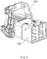
- Figs. 1 and 2 are different schematic structural views of a housing assembly for electrical connector according to exemplary embodiments of the present disclosure.
- Fig. 1 shows that a locking lever 200 is in a pre-locked position relative to a housing body 100
- Fig. 2 shows that the locking lever 200 is in a locked position relative to the housing body 100.
- Fig. 3 is a schematic structural view of a housing body of the housing assembly for electrical connector according to an exemplary embodiment of the present disclosure, and shows a groove 110 and a sliding groove 120 provided in the outer side surface of the housing body 100.
- Fig. 1 shows that a locking lever 200 is in a pre-locked position relative to a housing body 100
- Fig. 2 shows that the locking lever 200 is in a locked position relative to the housing body 100.
- Fig. 3 is a schematic structural view of a housing body of the housing assembly for electrical connector according to an exemplary embodiment of the present disclosure, and shows a groove 110 and a sliding groove 120 provided in the outer side surface of the housing body 100
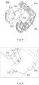
- FIG. 4 is a schematic structural view of the locking lever of the housing assembly for electrical connector according to an exemplary embodiment of the present disclosure, and shows an elastic protrusion 120 and an error-proofing stopper 220 provided on the inner side surface of the locking lever 200.
- Fig. 5 is a schematic enlarged view at the dashed box in Fig. 4 , and shows a specific structure of the elastic protrusion 120.
- Figs. 6-8 are partial schematic structural views of the housing assembly for electrical connector according to an exemplary embodiment of the present disclosure. For clarity, a portion of an arm portion of the locking lever 200 facing out of the paper is omitted in Figs.
- Fig. 6 shows the locking lever 200 in the pre-locked position
- Fig. 7 shows the locking lever 200 in the process of pivoting from the pre-locked position to the locked position
- Fig. 8 shows the locking lever 200 in the locked position.
- a housing assembly for electrical connector mainly includes: a housing body 100 and a locking lever 200.
- the housing body 100 has at least two ports, and connection terminals (not shown) for electrical connection can be provided in the housing body 100.
- the locking lever 200 is used to lock a connector including the housing body 100, to a mating connector that matches the connector.
- the locking lever 200 may be pivotally connected to the housing body 100, for example, by the pivot fitting relationship formed between a pivot shaft 130 (as shown in Fig. 3 ) formed on the housing body 100 and a pivot shaft hole 203 (as shown in Fig. 4 ) formed in the locking lever 200.
- the locking lever 200 is configured to pivot relative to the housing body 100 between a pre-locked position (as shown in Fig. 2 ) and a locked position (as shown in Fig. 1 ).
- a groove 110 is formed in the outer side surface of the housing body 100, and an elastic protrusion 210 is formed on the inner side surface of the locking lever 200.
- the groove 110 and the elastic protrusion 210 are configured such that: the elastic protrusion 210 is engaged into the groove 110 when the locking lever 200 is in the pre-locked position, as shown in Fig. 6 ; and the elastic protrusion 210 is disengaged from the groove 110 when the locking lever 200 leaves the pre-locked position, as shown in Figs. 7 and 8 .
- the locking lever can be stably locked in its pre-locked position by the engagement between the elastic protrusion formed on the locking lever and the groove formed in the housing body due to the aforementioned configuration, and when the locking lever needs to be pivoted to the locked position, only a small force needs to be applied to enable the locking lever to smoothly leave the pre-locked position, thus providing stable locking in the pre-locked position of the locking lever.
- the groove is formed in the outer side surface of the housing body, which can also reduce the size of the housing body and facilitate the miniaturization of the housing assembly.
- a sliding groove 120 is also formed in the outer side surface of the housing body 100.
- the sliding groove 120 is located adjacent to the groove 110, and the sliding groove 120 is configured such that: during the locking lever 200 pivots from the pre-locked position shown in Fig. 6 to the locked position shown in Fig. 8 , the boss 211 (which will be described in detail later) of the elastic protrusion disengaged from the groove 110 enters into the sliding groove 120 and travels along the sliding groove 120.
- the elastic protrusion 210 may further include: an elastic sheet 212 and the boss 211.
- the elastic sheet 212 extends from the inner side surface of the locking lever 200
- the boss 211 extends and protrudes from the elastic sheet 212.
- two opposite ends of the elastic sheet 212 extend from the inner side surface of the locking lever 200, respectively, two sides of the elastic sheet 212 adjacent to the two opposite ends are separated from the inner side surface of the locking lever 200, and the boss 211 is located approximately in the middle of the elastic sheet 212.
- the boss 211 may be formed by bending the elastic sheet 212.
- the locking lever 200 may adopt other suitable structures.
- only one end of the elastic sheet 212 extends from the inner side surface of the locking lever 200, for another example, the boss 211 is located at a free end of the elastic sheet 212, and so on.
- the elastic protrusion 210 is integrally formed with the inner side surface of the locking lever 200, but the present disclosure is not limited to this.
- a wall surface of the groove 110 near the sliding groove 120 is formed with a chamfer, and the boss 211 has an inclined face that matches the chamfer. Therefore, the boss 211 of the locking lever 200 is facilitated to slide smoothly into or out of the groove 110 formed in the housing body 100 by the fitting between the chamfer and the inclined face. Furthermore, a wall surface of the sliding groove 120 near the groove 110 is formed with a chamfer, which is facilitated for the boss 211 disengaged from the groove 110 to slide smoothly into or out of the sliding groove 120 formed in the housing body 100. It is possible to provide a better feel of the operation of the locking lever by the aforementioned configuration.
- the locking lever 200 further includes a pair of arm portions 201 and a connecting portion 202.
- the connecting portion 202 is connected to the pair of arm portions 201.
- the pair of arm portions 201 is pivotally connected to the opposite outer side surfaces of the housing body 100, respectively.
- the elastic protrusion 210 is formed on the inner side surface of each arm portion 201 of the pair of arm portions 201, and the groove 110 and the sliding groove 120 are correspondingly formed in each outer side surface of the opposite outer side surfaces of the housing body 100.
- the locking lever 200 is formed with an error-proofing stopper 220.
- the error-proofing stopper 220 is configured to prevent the locking lever 200 from being pivoted from the pre-locked position in a direction opposite to the locked position, thereby avoiding excessive free pivoting of the locking lever 200.
- the error-proofing stopper 220 extends from each arm portion 201 of the pair of arm portions 201 towards the outer side surface of the housing body 200. In this way, it can be abutted against a step of a rear end of the port of the housing body 100 when the locking lever 200 is in the pre-locked position, to prevent excessive free pivoting of the locking lever 200.
- the housing assembly for electrical connector provided by the exemplary embodiment of the present disclosure may be used as an outer housing of an electrical connector for electrical connection to a battery of a new energy vehicle so as to charge the battery.
- the locking lever can be stably locked in its pre-locked position by the engagement between the elastic protrusion formed on the locking lever and the groove formed in the housing body, and when the locking lever needs to be pivoted into the locked position, only a small force needs to be applied to enable the locking lever to smoothly leave the pre-locked position, in this way, a stable locking in the pre-locked position of the locking lever is provided.
- the housing assembly according to the forgoing various exemplary embodiments of the present disclosure it is only required that the groove is formed in the outer side surface of the housing body, which can also reduce the size of the housing body and facilitate the miniaturization of the housing assembly.
- the housing assembly according to the forgoing various exemplary embodiments of the present disclosure can also provide a better feel of the operation of the locking lever.
Landscapes
- Details Of Connecting Devices For Male And Female Coupling (AREA)
Applications Claiming Priority (1)
| Application Number | Priority Date | Filing Date | Title |
|---|---|---|---|
| CN202222689288.0U CN218867529U (zh) | 2022-10-12 | 2022-10-12 | 连接器外壳组件 |
Publications (2)
| Publication Number | Publication Date |
|---|---|
| EP4354673A1 true EP4354673A1 (de) | 2024-04-17 |
| EP4354673B1 EP4354673B1 (de) | 2026-04-01 |
Family
ID=87369383
Family Applications (1)
| Application Number | Title | Priority Date | Filing Date |
|---|---|---|---|
| EP23202886.0A Active EP4354673B1 (de) | 2022-10-12 | 2023-10-11 | Gehäuseanordnung für einen elektrischen verbinder |
Country Status (4)
| Country | Link |
|---|---|
| US (1) | US20240128684A1 (de) |
| EP (1) | EP4354673B1 (de) |
| JP (1) | JP2024057593A (de) |
| CN (1) | CN218867529U (de) |
Citations (4)
| Publication number | Priority date | Publication date | Assignee | Title |
|---|---|---|---|---|
| US7255581B2 (en) * | 2005-06-08 | 2007-08-14 | Sumitomo Wiring Systems, Ltd. | Lever-type connector |
| US10135183B1 (en) * | 2017-10-20 | 2018-11-20 | Lear Corporation | Electrical connector with assist lever |
| US20200388961A1 (en) * | 2019-06-07 | 2020-12-10 | Yazaki Corporation | Lever-type connector |
| US11296459B2 (en) * | 2019-07-12 | 2022-04-05 | Yazaki Corporation | Lever-type connector |
Family Cites Families (1)
| Publication number | Priority date | Publication date | Assignee | Title |
|---|---|---|---|---|
| JP6200933B2 (ja) * | 2015-11-10 | 2017-09-20 | タイコエレクトロニクスジャパン合同会社 | レバー式コネクタ組立体 |
-
2022
- 2022-10-12 CN CN202222689288.0U patent/CN218867529U/zh active Active
-
2023
- 2023-10-10 JP JP2023174899A patent/JP2024057593A/ja active Pending
- 2023-10-11 EP EP23202886.0A patent/EP4354673B1/de active Active
- 2023-10-12 US US18/485,354 patent/US20240128684A1/en active Pending
Patent Citations (4)
| Publication number | Priority date | Publication date | Assignee | Title |
|---|---|---|---|---|
| US7255581B2 (en) * | 2005-06-08 | 2007-08-14 | Sumitomo Wiring Systems, Ltd. | Lever-type connector |
| US10135183B1 (en) * | 2017-10-20 | 2018-11-20 | Lear Corporation | Electrical connector with assist lever |
| US20200388961A1 (en) * | 2019-06-07 | 2020-12-10 | Yazaki Corporation | Lever-type connector |
| US11296459B2 (en) * | 2019-07-12 | 2022-04-05 | Yazaki Corporation | Lever-type connector |
Also Published As
| Publication number | Publication date |
|---|---|
| US20240128684A1 (en) | 2024-04-18 |
| JP2024057593A (ja) | 2024-04-24 |
| EP4354673B1 (de) | 2026-04-01 |
| CN218867529U (zh) | 2023-04-14 |
Similar Documents
| Publication | Publication Date | Title |
|---|---|---|
| US7748993B2 (en) | Electrical connector with regulating portion for regulating elastic deformation of terminal | |
| KR100220352B1 (ko) | 개선된 캠 장치를 갖춘 전기 커넥터 조립체 | |
| JP3212210B2 (ja) | カム部材付きコネクタ | |
| US20020182908A1 (en) | Lever-Type Connector | |
| EP0790676B1 (de) | Hebelverbinder | |
| JP5945964B2 (ja) | コネクタ | |
| EP3425747B1 (de) | Verbinder | |
| US11942715B2 (en) | Terminal position assurance device and corresponding connector assembly | |
| CN101465500A (zh) | 杠杆型连接器 | |
| EP4354673A1 (de) | Gehäuseanordnung für einen elektrischen verbinder | |
| CN110838650A (zh) | 杠杆型连接器 | |
| EP0558947B1 (de) | Verbinder mit Hebel | |
| US20250047027A1 (en) | Electrical connector assembly having floating mating interface | |
| US20180248312A1 (en) | Lever-Type Connector | |
| CN115224536A (zh) | 杆式连接器 | |
| US7077675B2 (en) | ZIF connector in which a position of a contact is automatically adjusted during a connecting operation | |
| US20250007213A1 (en) | Connector and connector assembly | |
| CN215869938U (zh) | 连接器壳体组件及连接器组件 | |
| US5393238A (en) | Lever-actuated connector assembly | |
| JP2002025687A (ja) | レバー式コネクタ | |
| JP2002313487A (ja) | 分割コネクタ | |
| CN221552360U (zh) | 一种插头连接器 | |
| CN223039284U (zh) | 一种汽车信号连接器 | |
| CN110838651A (zh) | 杠杆型连接器 | |
| CN223624452U (zh) | 一种光纤连接器及连接器组件 |
Legal Events
| Date | Code | Title | Description |
|---|---|---|---|
| PUAI | Public reference made under article 153(3) epc to a published international application that has entered the european phase |
Free format text: ORIGINAL CODE: 0009012 |
|
| STAA | Information on the status of an ep patent application or granted ep patent |
Free format text: STATUS: THE APPLICATION HAS BEEN PUBLISHED |
|
| AK | Designated contracting states |
Kind code of ref document: A1 Designated state(s): AL AT BE BG CH CY CZ DE DK EE ES FI FR GB GR HR HU IE IS IT LI LT LU LV MC ME MK MT NL NO PL PT RO RS SE SI SK SM TR |
|
| STAA | Information on the status of an ep patent application or granted ep patent |
Free format text: STATUS: REQUEST FOR EXAMINATION WAS MADE |
|
| 17P | Request for examination filed |
Effective date: 20241017 |
|
| RBV | Designated contracting states (corrected) |
Designated state(s): AL AT BE BG CH CY CZ DE DK EE ES FI FR GB GR HR HU IE IS IT LI LT LU LV MC ME MK MT NL NO PL PT RO RS SE SI SK SM TR |
|
| GRAP | Despatch of communication of intention to grant a patent |
Free format text: ORIGINAL CODE: EPIDOSNIGR1 |
|
| STAA | Information on the status of an ep patent application or granted ep patent |
Free format text: STATUS: GRANT OF PATENT IS INTENDED |
|
| INTG | Intention to grant announced |
Effective date: 20251201 |
|
| P01 | Opt-out of the competence of the unified patent court (upc) registered |
Free format text: CASE NUMBER: UPC_APP_0001273_4354673/2026 Effective date: 20260114 |
|
| GRAS | Grant fee paid |
Free format text: ORIGINAL CODE: EPIDOSNIGR3 |
|
| GRAA | (expected) grant |
Free format text: ORIGINAL CODE: 0009210 |
|
| STAA | Information on the status of an ep patent application or granted ep patent |
Free format text: STATUS: THE PATENT HAS BEEN GRANTED |
|
| AK | Designated contracting states |
Kind code of ref document: B1 Designated state(s): AL AT BE BG CH CY CZ DE DK EE ES FI FR GB GR HR HU IE IS IT LI LT LU LV MC ME MK MT NL NO PL PT RO RS SE SI SK SM TR |
|
| REG | Reference to a national code |
Ref country code: CH Ref legal event code: F10 Free format text: ST27 STATUS EVENT CODE: U-0-0-F10-F00 (AS PROVIDED BY THE NATIONAL OFFICE) Effective date: 20260401 Ref country code: GB Ref legal event code: FG4D |
|
| REG | Reference to a national code |
Ref country code: DE Ref legal event code: R096 Ref document number: 602023014391 Country of ref document: DE |
|
| REG | Reference to a national code |
Ref country code: IE Ref legal event code: FG4D |