EP4354782A1 - Procédé et appareil de transmission d'informations - Google Patents
Procédé et appareil de transmission d'informations Download PDFInfo
- Publication number
- EP4354782A1 EP4354782A1 EP22827136.7A EP22827136A EP4354782A1 EP 4354782 A1 EP4354782 A1 EP 4354782A1 EP 22827136 A EP22827136 A EP 22827136A EP 4354782 A1 EP4354782 A1 EP 4354782A1
- Authority
- EP
- European Patent Office
- Prior art keywords
- quantization
- network
- information
- matrix
- branch
- Prior art date
- Legal status (The legal status is an assumption and is not a legal conclusion. Google has not performed a legal analysis and makes no representation as to the accuracy of the status listed.)
- Pending
Links
Images


Classifications
-
- H—ELECTRICITY
- H04—ELECTRIC COMMUNICATION TECHNIQUE
- H04B—TRANSMISSION
- H04B7/00—Radio transmission systems, i.e. using radiation field
- H04B7/02—Diversity systems; Multi-antenna system, i.e. transmission or reception using multiple antennas
- H04B7/04—Diversity systems; Multi-antenna system, i.e. transmission or reception using multiple antennas using two or more spaced independent antennas
- H04B7/0413—MIMO systems
- H04B7/0417—Feedback systems
-
- H—ELECTRICITY
- H04—ELECTRIC COMMUNICATION TECHNIQUE
- H04L—TRANSMISSION OF DIGITAL INFORMATION, e.g. TELEGRAPHIC COMMUNICATION
- H04L5/00—Arrangements affording multiple use of the transmission path
- H04L5/003—Arrangements for allocating sub-channels of the transmission path
- H04L5/0053—Allocation of signalling, i.e. of overhead other than pilot signals
-
- G—PHYSICS
- G06—COMPUTING OR CALCULATING; COUNTING
- G06N—COMPUTING ARRANGEMENTS BASED ON SPECIFIC COMPUTATIONAL MODELS
- G06N3/00—Computing arrangements based on biological models
-
- G—PHYSICS
- G06—COMPUTING OR CALCULATING; COUNTING
- G06N—COMPUTING ARRANGEMENTS BASED ON SPECIFIC COMPUTATIONAL MODELS
- G06N3/00—Computing arrangements based on biological models
- G06N3/02—Neural networks
- G06N3/04—Architecture, e.g. interconnection topology
- G06N3/045—Combinations of networks
-
- G—PHYSICS
- G06—COMPUTING OR CALCULATING; COUNTING
- G06N—COMPUTING ARRANGEMENTS BASED ON SPECIFIC COMPUTATIONAL MODELS
- G06N99/00—Subject matter not provided for in other groups of this subclass
-
- H—ELECTRICITY
- H04—ELECTRIC COMMUNICATION TECHNIQUE
- H04B—TRANSMISSION
- H04B7/00—Radio transmission systems, i.e. using radiation field
- H04B7/02—Diversity systems; Multi-antenna system, i.e. transmission or reception using multiple antennas
- H04B7/04—Diversity systems; Multi-antenna system, i.e. transmission or reception using multiple antennas using two or more spaced independent antennas
- H04B7/06—Diversity systems; Multi-antenna system, i.e. transmission or reception using multiple antennas using two or more spaced independent antennas at the transmitting station
- H04B7/0613—Diversity systems; Multi-antenna system, i.e. transmission or reception using multiple antennas using two or more spaced independent antennas at the transmitting station using simultaneous transmission
- H04B7/0615—Diversity systems; Multi-antenna system, i.e. transmission or reception using multiple antennas using two or more spaced independent antennas at the transmitting station using simultaneous transmission of weighted versions of same signal
- H04B7/0619—Diversity systems; Multi-antenna system, i.e. transmission or reception using multiple antennas using two or more spaced independent antennas at the transmitting station using simultaneous transmission of weighted versions of same signal using feedback from receiving side
- H04B7/0621—Feedback content
- H04B7/0626—Channel coefficients, e.g. channel state information [CSI]
-
- H—ELECTRICITY
- H04—ELECTRIC COMMUNICATION TECHNIQUE
- H04L—TRANSMISSION OF DIGITAL INFORMATION, e.g. TELEGRAPHIC COMMUNICATION
- H04L1/00—Arrangements for detecting or preventing errors in the information received
- H04L1/0001—Systems modifying transmission characteristics according to link quality, e.g. power backoff
- H04L1/0023—Systems modifying transmission characteristics according to link quality, e.g. power backoff characterised by the signalling
-
- H—ELECTRICITY
- H04—ELECTRIC COMMUNICATION TECHNIQUE
- H04L—TRANSMISSION OF DIGITAL INFORMATION, e.g. TELEGRAPHIC COMMUNICATION
- H04L1/00—Arrangements for detecting or preventing errors in the information received
- H04L1/0001—Systems modifying transmission characteristics according to link quality, e.g. power backoff
- H04L1/0023—Systems modifying transmission characteristics according to link quality, e.g. power backoff characterised by the signalling
- H04L1/0026—Transmission of channel quality indication
-
- H—ELECTRICITY
- H04—ELECTRIC COMMUNICATION TECHNIQUE
- H04W—WIRELESS COMMUNICATION NETWORKS
- H04W24/00—Supervisory, monitoring or testing arrangements
- H04W24/02—Arrangements for optimising operational condition
Definitions
- This application relates to the communication field, and more specifically, to an information transmission method and apparatus.
- a network device for example, a base station
- a terminal device needs to obtain downlink channel information fed back by a terminal device, to perform processing, for example, precoding, on downlink data.
- the terminal device compresses the channel information in spatial domain or frequency domain, for example, projects the channel information onto a discrete Fourier transform (discrete Fourier transform, DFT) substrate of the spatial domain or the frequency domain.
- DFT discrete Fourier transform
- An AI network architecture in a reuse form can meet different measurement configurations or feedback reporting configuration requirements. This helps increase feedback information precision and reduce overheads.
- an information transmission method including: receiving first indication information from a network device, where the first indication information indicates an association relationship between a plurality of branch networks in an artificial intelligence AI network and channel state information CSI measurement configuration information; and obtaining first quantization information based on a first branch network and channel information, where the first branch network is associated with current CSI measurement configuration information, and the first branch network belongs to the plurality of branch networks in the AI network.
- “Based on a first branch network and channel information” may also be expressed as processing the channel information based on the first branch network, or inputting the channel information into the first branch network. This is not limited in this application.
- the obtaining first quantization information based on a first branch network and channel information includes: obtaining a first matrix based on the first branch network and the channel information; and obtaining the first quantization information based on a first quantization network and the first matrix, where the first quantization network is associated with the current CSI measurement configuration information and/or the first branch network.
- the first indication information may indicate an association relationship between a plurality of quantization networks in the AI network and the channel state information CSI measurement configuration information, to indicate that the first quantization network is associated with the current CSI measurement configuration information and/or the first branch network.
- the quantization network in the AI network is obtained through training.
- the first matrix is quantized based on the quantization network, to obtain quantization information.
- the quantization information is sent to the network device, to further reduce the feedback overheads.
- the first indication information further indicates a quantization manner.
- the quantization manner includes at least a quantization direction or a quantization dimension.
- the obtaining the first quantization information based on a first quantization network and the first matrix includes: processing the first matrix based on the first quantization network in the quantization manner, to obtain the first quantization information.
- the quantization manner used by the quantization network is indicated, so that the feedback overheads can be reduced, and different measurement configurations or feedback reporting configuration requirements, for example, different feedback capacity requirements or feedback precision requirements can be met.
- the first quantization information includes second quantization information and third quantization information.
- the obtaining the first quantization information based on a first quantization network and the first matrix includes: dividing the first matrix into a second matrix and a third matrix in the quantization manner; and obtaining the second quantization information based on the first quantization network and the second matrix, and obtaining the third quantization information based on a second quantization network and the third matrix.
- the second quantization network is associated with the current CSI measurement configuration information and/or the first branch network.
- the first matrix is divided into a plurality of matrices for separate quantization, so that the AI network can perform parallel processing on the channel information, to increase an information processing speed and reduce a communication delay.
- the AI network may further include a fully connected layer.
- the first matrix is a first vector.
- the first vector may be divided into a plurality of vectors for separate quantization. In this way, complexity of high-dimensional space quantization can be avoided. This helps implement a small quantity of bits of feedback, increase the feedback information precision, and reduce the feedback overheads.
- obtaining the first quantization information based on a first quantization network and the first matrix includes: obtaining a fourth matrix based on a second branch network and the first matrix, where the second branch network is associated with the current CSI measurement configuration information, and the second branch network belongs to the plurality of branch networks in the AI network; and obtaining the first quantization information based on the fourth matrix.
- the obtaining the first quantization information based on the fourth matrix includes: obtaining the first quantization information based on a third quantization network and the fourth matrix, where the third quantization network is associated with the current CSI measurement configuration information and/or the second branch network.
- the first quantization information may further include both a quantization result of the fourth matrix and a quantization result of the first matrix.
- the method further includes: sending the first quantization information to the network device.
- the sending the first quantization information to the network device includes: sending the first quantization information to the network device in a preconfigured sequence.
- the preconfigured sequence includes at least one of the following: a line before column sequence, a column before line sequence, or a sequence of identifiers IDs of the branch networks.
- an information transmission method including: sending first indication information to a terminal device, where the first indication information indicates an association relationship between a plurality of branch networks in an artificial intelligence AI network and channel state information CSI measurement configuration information; and receiving first quantization information from the terminal device, where the first quantization information is obtained based on a first branch network and channel information, the first branch network is associated with current CSI measurement configuration information, and the first branch network belongs to the plurality of branch networks in the AI network.
- the first quantization information is obtained based on a first quantization network and a first matrix.
- the first matrix is obtained based on the first branch network and the channel information.
- the first quantization network is associated with the current CSI measurement configuration information and/or the first branch network.
- the first indication information may indicate an association relationship between a plurality of quantization networks in the AI network and the channel state information CSI measurement configuration information, to indicate that the first quantization network is associated with the current CSI measurement configuration information and/or the first branch network.
- the quantization network in the AI network is obtained through training.
- the terminal device quantizes the first matrix based on the quantization network, to obtain quantization information, and sends the quantization information to a network device, to further reduce the feedback overheads.
- the first indication information further indicates a quantization manner.
- the quantization manner includes at least a quantization direction or a quantization dimension.
- the first quantization information is obtained based on the first quantization network, the quantization manner, and the first matrix.
- the quantization manner used by the quantization network is indicated, so that the feedback overheads can be reduced, and different measurement configurations or feedback reporting configuration requirements, for example, different feedback capacity requirements or feedback precision requirements can be met.
- the first quantization information includes second quantization information and third quantization information.
- the second quantization information is obtained based on the first quantization network and a second matrix.
- the third quantization information is obtained based on a second quantization network and a third matrix.
- the second matrix and the third matrix are combined to form the first matrix.
- the second quantization network is associated with the current CSI measurement configuration information and/or the first branch network.
- the first matrix is divided into a plurality of matrices for separate quantization, so that the AI network can perform parallel processing on the channel information, to increase an information processing speed and reduce a communication delay.
- the AI network may further include a fully connected layer.
- the first matrix is a first vector.
- the first vector may be divided into a plurality of vectors for separate quantization. In this way, complexity of high-dimensional space quantization can be avoided. This helps implement a small quantity of bits of feedback, increase the feedback information precision, and reduce the feedback overheads.
- the first quantization information is obtained based on a fourth matrix.
- the fourth matrix is obtained based on a second branch network and the first matrix.
- the second branch network is associated with the current CSI measurement configuration information.
- the second branch network belongs to the plurality of branch networks in the AI network.
- the first quantization information is obtained based on a third quantization network and the fourth matrix.
- the third quantization network is associated with the current CSI measurement configuration information and/or the second branch network.
- the first quantization information may further include both a quantization result of the fourth matrix and a quantization result of the first matrix.
- the receiving first quantization information from the terminal device includes: receiving the first quantization information from the terminal device in a preconfigured sequence.
- the preconfigured sequence includes at least one of the following: a line before column sequence, a column before line sequence, or a sequence of identifiers IDs of the branch networks.
- an information transmission apparatus including: A transceiver unit is configured to receive first indication information from a network device.
- the first indication information indicates an association relationship between a plurality of branch networks in an artificial intelligence AI network and channel state information CSI measurement configuration information.
- a processing unit is configured to obtain first quantization information based on a first branch network and channel information.
- the first branch network is associated with current CSI measurement configuration information.
- the first branch network belongs to the plurality of branch networks in the AI network.
- the processing unit is specifically configured to: obtain a first matrix based on the first branch network and the channel information; and obtain the first quantization information based on a first quantization network and the first matrix.
- the first quantization network is associated with the current CSI measurement configuration information and/or the first branch network.
- the first indication information further indicates a quantization manner.
- the quantization manner includes at least a quantization direction or a quantization dimension.
- the processing unit is specifically configured to process the first matrix based on the first quantization network in the quantization manner, to obtain the first quantization information.
- the first quantization information includes second quantization information and third quantization information.
- the processing unit is specifically configured to: divide the first matrix into a second matrix and a third matrix in the quantization manner; and obtain the second quantization information based on the first quantization network and the second matrix, and obtain the third quantization information based on a second quantization network and the third matrix.
- the second quantization network is associated with the current CSI measurement configuration information and/or the first branch network.
- the first quantization information is obtained based on the first quantization network and the first matrix.
- the processing unit is specifically configured to: obtain a fourth matrix based on a second branch network and the first matrix, where the second branch network is associated with the current CSI measurement configuration information, and the second branch network belongs to the plurality of branch networks in the AI network; and obtain the first quantization information based on the fourth matrix.
- the processing unit is specifically configured to obtain the first quantization information based on a third quantization network and the fourth matrix.
- the third quantization network is associated with the current CSI measurement configuration information and/or the second branch network.
- the transceiver unit is further configured to send the first quantization information to the network device.
- the transceiver unit is specifically configured to send the first quantization information to the network device in a preconfigured sequence.
- the preconfigured sequence includes at least one of the following: a line before column sequence, a column before line sequence, or a sequence of identifiers IDs of the branch networks.
- an information transmission apparatus including: A transceiver unit is configured to send first indication information to a terminal device.
- the first indication information indicates an association relationship between a plurality of branch networks in an artificial intelligence AI network and channel state information CSI measurement configuration information.
- the transceiver unit is further configured to receive first quantization information from the terminal device.
- the first quantization information is obtained based on a first branch network and channel information.
- the first branch network is associated with current CSI measurement configuration information.
- the first branch network belongs to the plurality of branch networks in the AI network.
- the first quantization information is obtained based on a first quantization network and a first matrix.
- the first matrix is obtained based on the first branch network and the channel information.
- the first quantization network is associated with the current CSI measurement configuration information and/or the first branch network.
- the first indication information may indicate an association relationship between a plurality of quantization networks in the AI network and the channel state information CSI measurement configuration information, to indicate that the first quantization network is associated with the current CSI measurement configuration information and/or the first branch network.
- the first indication information further indicates a quantization manner.
- the quantization manner includes at least a quantization direction or a quantization dimension.
- the first quantization information is obtained based on the first quantization network, the quantization manner, and the first matrix.
- the first quantization information includes second quantization information and third quantization information.
- the second quantization information is obtained based on the first quantization network and a second matrix.
- the third quantization information is obtained based on a second quantization network and a third matrix.
- the second matrix and the third matrix are combined to form the first matrix.
- the second quantization network is associated with the current CSI measurement configuration information and/or the first branch network.
- the AI network may further include a fully connected layer.
- the first matrix is a first vector.
- the first vector may be divided into a plurality of vectors for separate quantization. In this way, complexity of high-dimensional space quantization can be avoided. This helps implement a small quantity of bits of feedback, increase the feedback information precision, and reduce the feedback overheads.
- the first quantization information is obtained based on a fourth matrix.
- the fourth matrix is obtained based on a second branch network and the first matrix.
- the second branch network is associated with the current CSI measurement configuration information.
- the second branch network belongs to the plurality of branch networks in the AI network.
- the first quantization information is obtained based on a third quantization network and the fourth matrix.
- the third quantization network is associated with the current CSI measurement configuration information and/or the second branch network.
- the transceiver unit is specifically configured to receive the first quantization information from the terminal device in a preconfigured sequence.
- the preconfigured sequence includes at least one of the following: a line before column sequence, a column before line sequence, or a sequence of identifiers IDs of the branch networks.
- a communication apparatus includes a processor.
- the processor is coupled to a memory.
- the memory is configured to store a program or instructions.
- the apparatus is enabled to implement the method in any one of the first aspect, the second aspect, the implementations of the first aspect, and the implementations of the second aspect.
- processors there are one or more processors, and there are one or more memories.
- the memory and the processor may be integrated together, or the memory and the processor are separately disposed.
- a communication system includes a terminal device and a network device.
- the terminal device is configured to implement the method in each implementation of the first aspect
- the network device is configured to implement the method in each implementation of the second aspect.
- the communication system further includes another device that interacts with the terminal device in the solutions provided in embodiments of this application.
- a computer program product includes a computer program or instructions.
- the computer program or the instructions are run on a computer, the computer is enabled to perform the method in the foregoing aspects.
- the computer program or the instructions may be stored in a first storage medium.
- the first storage medium may be packaged together with a processor, or may be packaged separately from a processor. This is not specifically limited in embodiments of this application.
- a computer-readable medium stores a computer program or instructions.
- the computer program or the instructions are run on a computer, the computer is enabled to perform the method in the foregoing aspects.
- a chip system includes a memory and a processor.
- the memory is configured to store a computer program
- the processor is configured to invoke and run the computer program from the memory, to enable a communication device in which the chip system is installed to perform the method in any one of the first aspect, the second aspect, the implementations of the first aspect, and the implementations of the second aspect.
- the chip system may include an input chip or interface configured to send information or data, and an output chip or interface configured to receive information or data.
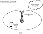
- FIG. 1 is a schematic diagram of a communication system 100 to which an embodiment of this application is applicable.
- the communication system 100 may include a network device 101 and a terminal device 102, and optionally, may further include a core network device 103.
- the network device 101 can communicate with the core network device 103, and the terminal device 102 can communicate with the network device 101.
- the terminal device in this embodiment of this application may also be referred to as user equipment, an access terminal, a subscriber unit, a subscriber station, a mobile station, a remote station, a remote terminal, a mobile device, a user terminal, a wireless communication device, a user agent, a user apparatus, or the like.
- the terminal device in this embodiment of this application may be a mobile phone (mobile phone), a tablet computer (pad), a computer having a wireless transceiver function, a virtual reality (virtual reality, VR) terminal, an augmented reality (augmented reality, AR) terminal, a wireless terminal in industrial control (industrial control), a wireless terminal in self driving (self driving), a wireless terminal in telemedicine (telemedicine), a wireless terminal in a smart grid (smart grid), a wireless terminal in transportation safety (transportation safety), a wireless terminal in a smart city (smart city), a wireless terminal in a smart home (smart home), a cellular phone, a cordless phone, a session initiation protocol (session initiation protocol, SIP) phone, a wireless local loop (wireless local loop, WLL) station, a personal digital assistant (personal digital assistant, PDA), a handheld device having a wireless communication function, a computing device or another processing device connected to a wireless modem, a vehicle-mounted device, a wearable device,
- the wearable device may also be referred to as a wearable smart device, and is a general term of wearable devices, for example, glasses, gloves, watches, clothes, and shoes, that are developed by applying wearable technologies to intelligent designs of daily wear.
- the wearable device is a portable device that is directly worn on a body or integrated into clothes or an accessory of a user.
- the wearable device is not only a hardware device, but also implements a powerful function through software support, data exchange, and cloud interaction.
- Generic wearable smart devices include full-featured and large-size devices that can implement complete or partial functions without depending on smartphones, for example, smart watches or smart glasses, and devices that focus only on a type of application function and need to work with other devices such as smartphones, for example, various smart bands or smart jewelry for monitoring physical symptoms.
- the terminal device may alternatively be a terminal device in an internet of things (internet of things, IoT) system.
- IoT internet of things
- a technical feature of the IoT is to connect an object to a network by using a communication technology, to implement an intelligent network of human-machine interconnection and thing-thing interconnection.
- a specific form of the terminal device is not limited in this application.
- the terminal device may be an apparatus configured to implement a function of the terminal device, or may be an apparatus, for example, a chip system, that can support the terminal device in implementing the function.
- the apparatus may be installed in the terminal.
- the chip system may include a chip, or may include a chip and another discrete component.
- the network device in this embodiment of this application may be any device having a wireless transceiver function.
- the device includes but is not limited to an evolved NodeB (evolved NodeB, eNB), a home NodeB (for example, a home evolved NodeB, or a home NodeB, HNB), a baseband unit (base band unit, BBU), an access point (access point, AP) in a wireless fidelity (wireless fidelity, Wi-Fi) system, a wireless relay node, a wireless backhaul node, a transmission point (transmission point, TP) or a transmission reception point (transmission reception point, TRP), or the like, or may be a next generation NodeB (next generation NodeB, gNB) in a 5th generation (5th generation, 5G), for example, a new radio (new radio, NR) wireless communication system, a transmission point (TRP or TP), one or a group of (including a plurality of antenna panels) antenna panels of a base
- the gNB may include a central unit (central unit, CU) and the DU.
- the CU performs some functions of the gNB, and the DU performs some functions of the gNB.
- the CU is responsible for processing a non-real-time protocol and service, and implements functions of radio resource control (radio resource control, RRC) and a packet data convergence protocol (packet data convergence protocol, PDCP) layer.
- the DU is responsible for processing a physical layer protocol and a real-time service, and implements functions of a radio link control (radio link control, RLC) layer, a media access control (media access control, MAC) layer, and a physical (physical, PHY) layer.
- radio link control radio link control
- MAC media access control
- PHY physical
- the gNB may further include an active antenna unit (active antenna unit, AAU for short).
- the AAU implements some physical layer processing functions, radio frequency processing, and a function related to an active antenna.
- Information at the RRC layer is eventually converted into information at the PHY layer, or is converted from information at the PHY layer. Therefore, in this architecture, higher layer signaling, for example, RRC layer signaling may also be considered as being sent by the DU or sent by the DU and the AAU.
- the network device may be a device including one or more of a CU node, a DU node, and an AAU node.
- the CU may be classified into a network device in an access network (radio access network, RAN), or the CU may be classified into a network device in a core network (CN). This is not limited in this application.
- the network device may be an apparatus configured to implement a function of the network device, or may be an apparatus, for example, a chip system, that can support the network device in implementing the function.
- the apparatus may be installed in the network device.
- embodiments of this application relate to massive application of a neural network, for ease of understanding, the following describes terms and concepts related to the neural network that may be used in embodiments of this application.
- the neural network may include a neural unit.
- the neural unit may be an operation unit with xs as an input.
- s 1, 2, ..., n, n is a natural number greater than 1
- Ws is a weight of xs
- b is a bias of the neural unit, and corresponds to an intercept 1 that is input.
- f is an activation function (activation function) of the neural unit, and is used for introducing a non-linear feature into the neural network, to convert an input signal in the neural unit into an output signal.
- the output signal of the activation function may serve as an input of a next layer.
- the activation function may be a rectified linear function (Rectified Linear Unit, ReLU), a hyperbolic tangent function tanh, or a sigmoid function.
- the neural network is a network formed by connecting a plurality of single neural units together.
- an output of a neural unit may be an input of another neural unit.
- An input of each neural unit may be connected to a local receptive field of a previous layer to extract a feature of the local receptive field.
- the local receptive field may be a region including several neural units.
- the deep neural network also referred to as a multi-layer neural network
- DNN may be understood as a neural network having a plurality of hidden layers.
- the DNN is divided based on locations of different layers.
- the neural network in the DNN may be divided into three types: an input layer, a hidden layer, and an output layer.
- a first layer is the input layer
- the last layer is the output layer
- a middle layer is the hidden layer.
- Layers are fully connected, to be specific, any neuron in the ith layer is definitely connected to any (or each) neuron in the (i+1) th layer.
- the DNN seems complex, it is not complex in terms of work at each layer.
- the output vector is obtained by performing such a simple operation on the input vector x . Due to a large quantity of DNN layers, quantities of coefficients W and bias vectors b are also large. Definitions of these parameters in the DNN are as follows.
- the coefficient W is used as an example.
- a linear coefficient from the fourth neuron at the second layer to the second neuron at the third layer is defined as W 24 3 .
- the superscript 3 indicates that a layer number in which the coefficient W is located is the third layer, and the subscript corresponds to a third layer index 2 that is output and a second layer index 4 that is input.
- a coefficient from the k th neuron of the (L-1) th layer to the j th neuron of the Lth layer is defined as W jk L .
- a process of training the deep neural network is a process of learning the weight matrix.
- a final objective of training is to obtain weight matrices (weight matrices formed by vectors W at many layers) of all layers of the trained deep neural network.
- the convolutional neural network (convolutional neuron network, CNN) is a deep neural network with a convolutional structure.
- the convolutional neural network includes a feature extractor that includes a convolutional layer and a sub-sampling layer.
- the feature extractor may be considered as a filter.
- the convolutional layer is a neuron layer that is in the convolutional neural network and at which convolution processing is performed on an input signal.
- one neuron may be connected only to some adjacent-layer neurons.
- One convolutional layer usually includes several feature planes. Each feature plane may include some neural units that are in a rectangular arrangement. Neural units at a same feature plane share a weight, and the weight shared herein is a convolution kernel.
- Sharing the weight may be understood as that a channel information extraction manner is irrelevant to a location.
- the convolution kernel may be formalized in a matrix of a random size.
- an appropriate weight may be obtained for the convolution kernel through learning.
- benefits directly brought by sharing the weight are that connections among layers of the convolutional neural network are reduced, and an overfitting risk is reduced.
- the network device for example, a base station
- MCS modulation and coding scheme
- the network device needs to obtain downlink channel information fed back by the terminal device, to precode data in a downlink direction and determine a modulation and coding scheme (modulation and coding scheme, MCS).
- MCS modulation and coding scheme
- the downlink channel information may be obtained on a base station side via a sounding reference signal (sounding reference signal, SRS).
- SRS sounding reference signal
- the information needs to be obtained through measurement and feedback of the UE.
- Information of channel state information includes a precoding matrix indicator (precoding matrix indicator, PMI), a rank indicator (rank indicator, RI), a channel quality indicator (channel quality indicator, CQI), a layer 1-reference signal received power (layer 1-reference signal received power, L1-RSRP), and another parameter, and is used for describing the downlink channel information.
- precoding matrix indicator precoding matrix indicator, PMI
- rank indicator rank indicator
- CQI channel quality indicator
- L1-RSRP layer 1-reference signal received power
- a CSI-feedback-related configuration includes a measurement resource configuration and a reporting configuration.
- the measurement configuration mainly refers to a configuration of a related measurement resource, for example, a quantity of antenna ports (ports), a periodicity, and a time-frequency domain location of a channel state information reference signal (channel state information reference signal, CSI-RS) resource.
- the reporting configuration refers to a CSI-reporting-related configuration, for example, reporting content (for example, PMI/RI), a reporting periodicity, and a codebook type based on which reporting is performed.
- Each CSI measurement resource configuration and each reporting configuration are combined into one CSI measurement configuration.
- the network device for example, the base station
- the terminal device measures a measurement resource in the measurement configuration, and reports the CSI based on a reporting configuration in the measurement configuration.
- Two CSI reporting feedback modes are specified in R15, and are specific used modes indicated by the network device (for example, the base station) to the terminal device in an RRC configuration.
- the terminal device estimates current channel information (which is usually a two-dimensional spatial-frequency domain complex number matrix) by measuring a CSI-RS signal.
- a current feedback mechanism is performed based on a codebook. Different quantities of CSI-RS antenna ports and different space ranks have different codeword ranges.
- the type II information only about one codeword is fed back, and feedback precision is excessively low.
- a plurality of codewords may be fed back, in other words, a linear combination of a plurality of codewords is used for describing a channel. Therefore, compared with the feedback of the type I, the feedback of the type II has higher precision, but brings more feedback overheads.
- AI artificial intelligence
- a plurality of local features of an image may be extracted and matched by using the CNN network, to form descriptions of an advanced feature of the image, and used for image classification, compression, and the like.
- Combination of the AI technology and a wireless air interface technology is also one of research directions of current wireless communication.
- the terminal device may input a measured channel into an encoding network, and compress the measured channel into an encoding vector.
- a network device side may restore an original channel based on the compression vector by using a decoding network adapted to the compression vector.
- the CSI feedback based on the autoencoder is used as an example.
- the autoencoder is a general name of a type of AI network structure, and usually includes two parts: an encoder and a decoder.
- a trained encoder and a trained decoder are respectively located on a terminal device side and the network device (for example, the base station) side.
- the network device for example, the base station
- On the terminal device side to obtain a channel characteristic with a sparse structure, first, a two-dimensional frequency-spatial domain channel that is input is converted into a two-dimensional delay-angular domain channel, and then a truncated delay-angular domain channel serves as an input of an AI network. After a channel matrix is input to an encoding network on the terminal device side, one vector is obtained.
- the vector further serves as an input of a decoder side on the network device (for example, the base station) side. After the vector passes through the decoder, a two-dimensional delay-angular domain matrix is obtained. The two-dimensional delay-angular domain matrix is further converted into a frequency-spatial domain channel through inverse conversion, to complete channel information restoration.
- a scalar quantization manner is proposed in the industry to quantize each dimension of the output vector.
- mainstream scalar quantization manners include equal-length quantization and unequal-length quantization.
- the equal-length quantization is that each dimension is quantized in a uniform quantization manner.
- the unequal-length quantization for example, entropy encoding quantization, is to first perform a rounding operation on each dimension of a floating point output to obtain a series of discrete values. Then, based on distribution of all dimensions of discrete values, coding schemes of different discrete values are obtained.
- the scalar quantization manner usually has a discontinuous operation, for example, rounding, so that training of the entire AI network is unfeasible.
- a quantization process cannot be integrated into a training process of the autoencoder, and some information redundancy may also exist.
- this application provides an information transmission method, to expect to meet different measurement configurations or feedback reporting configuration requirements, to increase feedback information precision, and to reduce overheads.
- FIG. 2 is a schematic diagram of a structure of a simple neural network 200 to which this application is applicable.
- (a) in FIG. 2 may be used for describing a logical relationship of a neural network, for example, a neural network including two network layers.
- (a) in FIG. 2 may also be expressed as a three-layer neural network, to be specific, an output of a network layer 2 may also be separately expressed as a neural network layer. This is not limited in this application.
- FIG. 2 is a detailed expanded diagram of (a) in FIG. 2 .
- a network layer 1 is in a one-to-one mapping relationship, to be specific, all elements that are input are mapped to output neurons of the network layer 1 one by one. For example, if a three-dimensional column vector is input, the network layer 1 maps a vector and that is in each dimension to three output neurons of the layer one by one.
- the network layer 2 is a fully connected layer. It is assumed that there are four output neurons of the network layer 2. Without biasing, the network layer 2 includes 12 weights. The four output neurons of the network layer 2 may be obtained by performing a linear multiplication operation on the output of the network layer 1, and adding a non-linear activation operation.
- the neural network may generally include numerous network layers or numerous subnetworks, for example, a deep learning network.
- different network layers are sequentially connected to form an AI network.
- a plurality of network layers sequentially operate an input of the network, to obtain an output of the network.
- a branch network may be led out from an intermediate network layer, and serves as the output of the network.
- a branch network 1 is operated by the network layer 1
- a branch network 2 is operated by the network layer 1 and the network layer 2.
- a quantization network has parameters and structures that may be reused. For example, as shown in (d) in FIG. 2 , for different measurement resource configurations or branch networks, different quantization layers are associated, to form a plurality of quantization networks. For example, when a quantity of CSI-RS antenna ports in a measurement configuration is small, a quantization network with a low quantization dimension is associated; or when a requirement on feedback precision in a measurement configuration is high, a quantization network with a high quantization dimension is associated. For example, a quantization network 1 is operated by a quantization layer 1, and a quantization network 2 is operated by the quantization layer 1 and a quantization layer 2.
- FIG. 3 is a schematic diagram of a logical structure of a neural network to which this application is applicable.
- the neural network includes two functions. First, AI encoding is performed on channel information. Specifically, the channel information may be compressed, and coded into one or more vectors/matrices (real numbers). Then, a result obtained through AI encoding needs to be quantized. Specifically, after the result obtained through AI encoding passes through a quantization layer, one or more quantization indexes are obtained, to implement discretization representation of feedback information, and then the feedback information is fed back to a network device (for example, a base station). It should be noted that in this application, a quantization network is obtained through AI training.
- a quantization manner may specifically include a quantization dimension, a quantization direction, and the like.
- the quantization manner is defined as performing quantization for a specific dimension and a specific dimension range for a vector that is output or a matrix that is output through AI encoding.
- a three-dimensional matrix is output through AI encoding, and three dimensions are represented as [H, W, D].
- H, W, and D may respectively represent a length, a width, and a depth of an image.
- H, W, and D may respectively represent an angular domain, a delay domain, and a feature domain of a channel.
- the quantization direction refers to quantization for one or more dimensions of the H dimension, the W dimension, and the D dimension.
- the quantization dimension means that, for example, when the quantization direction is the H dimension, the length is 32; when the quantization dimension is 32, quantization is performed on a vector of 1*32; or when the quantization dimension is 16, quantization is performed on a vector of 1*16.
- a configuration may not be displayed and an AI encoding layer network may not be distinguished from a quantization layer network, but an AI network is configured as a whole, for example, the three-layer AI network in (c) in FIG. 2 .
- the network layer 1 and the network layer 2 may perform an AI encoding function, and the network layer 3 may perform a quantization layer function.
- An AI network on a network device (for example, the base station) side and an AI network on the UE side are trained together.
- the network device for example, the base station
- channel data is collected within a coverage area of the network device.
- An encoding network, the quantization network, and a decoding network are jointly trained on the network device (for example, the base station) side, to obtain one AI network.
- the network device uses the encoding network and the quantization network as networks on the UE side, and configures the encoding network and the quantization network for UE in a service range of the network device.
- the network device stores the decoding network. Therefore, the network device (for example, the base station) may perform operations, for example, dequantization and decoding on information fed back by the UE, to obtain correct feedback information.
- FIG. 4 is a schematic flowchart of an information transmission method according to this application.
- the terminal device 102 receives first indication information from the network device 101, where the first indication information indicates an association relationship between a plurality of branch networks in an artificial intelligence AI network and channel state information CSI measurement configuration information.
- the AI network may be configured by the network device 101 for the terminal device 102, or may be obtained by the terminal device 102 in a local configuration. This is not limited in this application.
- the terminal device 102 obtains first quantization information based on a first branch network and channel information, where the first branch network is associated with current CSI measurement configuration information, and the first branch network belongs to the plurality of branch networks in the AI network.
- “Based on a first branch network and channel information” may also be expressed as processing the channel information based on the first branch network, or inputting the channel information into the first branch network. This is not limited in this application.
- the obtaining first quantization information based on a first branch network and channel information includes: obtaining a first matrix based on the first branch network and the channel information; and obtaining the first quantization information based on a first quantization network and the first matrix, where the first quantization network is associated with the current CSI measurement configuration information and/or the first branch network.
- the first indication information may indicate an association relationship between a plurality of quantization networks in the AI network and the channel state information CSI measurement configuration information, to indicate that the first quantization network is associated with the current CSI measurement configuration information and/or the first branch network.
- the first indication information further indicates a quantization manner.
- the quantization manner includes at least a quantization direction or a quantization dimension.
- the obtaining the first quantization information based on a first quantization network and the first matrix includes: processing the first matrix based on the first quantization network in the quantization manner, to obtain the first quantization information.
- the first quantization information includes second quantization information and third quantization information.
- the obtaining the first quantization information based on a first quantization network and the first matrix includes: dividing the first matrix into a second matrix and a third matrix in the quantization manner; and obtaining the second quantization information based on the first quantization network and the second matrix, and obtaining the third quantization information based on a second quantization network and the third matrix.
- the second quantization network is associated with the current CSI measurement configuration information and/or the first branch network.
- the obtaining the first quantization information based on a first quantization network and the first matrix includes: obtaining a fourth matrix based on a second branch network and the first matrix, where the second branch network is associated with the current CSI measurement configuration information, and the second branch network belongs to the plurality of branch networks in the AI network; and obtaining the first quantization information based on the fourth matrix.
- the obtaining the first quantization information based on the fourth matrix includes: obtaining the first quantization information based on a third quantization network and the fourth matrix, where the third quantization network is associated with the current CSI measurement configuration information and/or the second branch network.
- the first quantization information may further include both a quantization result of the fourth matrix and a quantization result of the first matrix.
- the method further includes: sending the first quantization information to the network device.
- the sending the first quantization information to the network device includes: sending the first quantization information to the network device in a preconfigured sequence.
- the preconfigured sequence includes at least one of the following: a line before column sequence, a column before line sequence, or a sequence of identifiers IDs of the branch networks.
- FIG. 5 is a schematic flowchart of a specific example of an information transmission method according to this application.
- the terminal device 102 receives an AI network from the network device 101, where the AI network includes a plurality of branch networks.
- the network device may configure the AI network for the terminal device 102 via higher layer signaling.
- This may specifically include a network parameter and a network structure of the AI network.
- information about the network structure may include a type of a used network layer, to be specific, the network layer belongs to a convolutional layer, a fully connected layer, and the like.
- the network parameter may include a quantity of neurons, a network weight between each neuron and an upper-layer neuron, and the like.
- the network parameter may further include a logical identifier of the network layer or the branch network, for example, a number of the network layer or a number of the branch network.
- the network device 101 may configure the network structure and parameter information by using an RRC message, for example, add a new field to an RRC information element, to indicate or describe the structure and the parameter of the entire AI network.
- the network device 101 may pack the entire network structure and the parameter into one piece of large application data, and send the one piece of large application data as application layer data on a network side to UE, for example, send the one piece of large application data by using a non-access stratum (non-access stratum, NAS) message.
- NAS non-access stratum
- the AI network is a network of a fully convolutional structure. An information compression part is all completed by the convolutional layer.
- the AI network may include nine convolution layers, to separately form the branch network.
- a specific convolution parameter may be shown in Table 1.
- the AI network configured by the network device 101 further includes a quantization network (or a quantization layer) used for quantization.
- the network device 101 may configure a large parameter matrix, and associate different submatrix parameter combinations for different measurement resource configurations or reporting configurations, to form a plurality of submatrices.
- the plurality of submatrices serve as parameters of the quantization layer in the AI network to form different quantization networks.
- the terminal device 102 receives first indication information from the network device 101, where the first indication information indicates an association relationship between the plurality of branch networks in the AI network and CSI measurement configuration information.
- the CSI measurement configuration information may be the CSI-feedback-related configuration described above, and may include a measurement resource configuration and a reporting configuration.
- the measurement configuration mainly refers to a configuration of a related measurement resource, for example, a quantity of antenna ports (ports), a periodicity, and a time-frequency domain location of a CSI-RS resource.
- the reporting configuration refers to a CSI-reporting-related configuration, for example, reporting content (for example, PMI/RI), a reporting periodicity, and a codebook type based on which reporting is performed. It should be noted that with development of technologies, the CSI measurement configuration information may further include other CSI-feedback-related configuration information. This is not limited in this application.
- the AI network configured by the network device 101 for the terminal device may include a plurality of network branches. Different network branches are associated with different measurement resource configurations or reporting configurations in the CSI measurement configuration information. In actual application, a field may be added to a related RRC field of the measurement configuration to describe the ID of the branch network (or the network layer at which the branch network is located).
- H is a channel matrix that is input
- P is a size of an antenna domain of a channel
- D is a size of a delay domain of a channel.
- a branch network 1 is used.
- the branch network 1 becomes a matrix whose size is [P/2, D/2], and the matrix serves as an input of the quantization layer.
- the branch network 3 is used. After three times of convolution and down-sampling, the branch network 3 becomes a matrix whose size is [P/8, D/8], and the matrix serves as an input of the quantization layer.
- a feedback capacity in the reporting configuration when a feedback capacity in the reporting configuration is limited, it indicates that a quantity of vectors that need to be quantized is small. Therefore, the branch network 3 is used, and three times of convolution and down-sampling are performed to obtain a small matrix for quantization.
- a feedback capacity in the reporting configuration is not limited, it indicates that a quantity of vectors that need to be quantized may be large. Therefore, the branch network 1 is used, and only one time of convolution and down-sampling is performed to obtain a large matrix for quantization.
- the terminal device 102 obtains a first matrix based on a first branch network and channel information, where the first branch network is associated with current CSI measurement configuration information, and the first branch network belongs to the plurality of branch networks in the AI network.
- the terminal device 102 may determine the first branch network based on the current CSI measurement configuration information, to process channel information obtained based on the current CSI measurement configuration information.
- the first branch network may be the branch network 1, a branch network 2, or the branch network 3 shown in FIG. 6 .
- the terminal device 102 may obtain a channel response estimation value on a corresponding time-frequency resource on each antenna port according to a method, for example, minimum square estimation. Further, frequency domain information of all antenna ports at a measurement moment may be obtained, to obtain a spatial-frequency domain channel information matrix.
- the quantity of CSI-RS antenna ports is 32, and a frequency band resource for measurement is 100 RBs. In this case, a 32*100 matrix may be obtained, indicating channel information on each antenna port on each RB.
- the terminal device 102 may further convert the channel information matrix, and convert the channel into an angular-delay domain channel by using DFT transform. This helps compress the channel information.
- the terminal device 102 may further crop the angular-delay domain channel in the delay domain. For example, 32 pieces of information in the delay domain are reserved in an original 32*100 channel and the original 32*100 channel is cropped into a 32*32 matrix.
- the terminal device 102 may further convert the converted angular-delay domain channel into a three-dimensional real matrix, and input the three-dimensional real matrix to the determined first branch network to obtain the first matrix.
- a 32*32 complex matrix is divided into a real part and an imaginary part to form a 32*32*2 real matrix, and the matrix is input to the first branch network (for example, the first branch network may be the branch network 3 in FIG. 6 ).
- the first branch network may be the branch network 3 in FIG. 6 .
- a 16-dimensional feature is extracted, and an original [32, 32, 2] matrix is converted into a [4, 4, 16] matrix.
- the terminal device 102 obtains first quantization information based on the first quantization network and the first matrix, where the first quantization network is associated with the current CSI measurement configuration information and/or the first branch network.
- the network device 101 may indicate an association relationship between a plurality of quantization networks in the AI network and the channel state information CSI measurement configuration information by using the first indication information. Because the plurality of branch networks in the AI network are associated with the CSI measurement configuration information, to indicate that the first quantization network is associated with the current CSI measurement configuration information and/or the first branch network. In this case, the terminal device 102 may determine the first quantization network based on the current CSI measurement configuration information and/or the first branch network, where the first quantization network belongs to the plurality of quantization networks in the AI network.
- the network device 101 may indicate an association relationship between the plurality of quantization networks in the AI network and the channel state information CSI measurement configuration information and an association relationship between the plurality of quantization networks in the AI network and the plurality of branch networks by using the first indication information.
- the network device 101 may indicate an association relationship between the plurality of quantization networks and the plurality of branch networks in the AI network by using the first indication information.
- the network device 101 may further configure different quantization manners for different quantization networks in the CSI measurement configuration information.
- the quantization manner includes a quantization direction and a quantization dimension.
- a three-dimensional input matrix may be converted into a matrix whose size is [P, D, C] through a convolution operation.
- P may be represented as an antenna domain
- D may be represented as the delay domain
- C may be represented as a feature domain.
- Indicating the quantization direction refers to indicating to perform quantization by using one or more dimensions of a P dimension, a D dimension, and a C dimension.
- the network device 101 may indicate to subsequently perform quantization on the C dimension.
- Indicating the quantization dimension refers to indicating a quantity of to-be-quantized dimensions in one or more dimensions, for example, indicating to subsequently perform quantization on 16 dimensions in a C dimension direction.
- the first matrix is [4, 4, 16].
- Quantization is performed on a third-dimensional feature domain based on a previous configuration, to determine that to-be-quantized vectors are 4*4 16*1 vectors, which is equivalent to a 4*4 vector matrix.
- x is the to-be-quantized vector
- wm is all the column vectors in the quantization network.
- calculation may be performed according to another distance calculation method that is pre-agreed upon or configured, for example, a Manhattan distance. This is not limited in this application.
- the original vector matrix becomes a scalar matrix.
- the original three-dimensional matrix [4, 4, 16] may be quantized into a two-dimensional matrix [4, 4].
- Each location represents quantization index information of a corresponding location vector, and may be referred to as the first quantization information in this application.
- the terminal device 102 sends the first quantization information to the network device 101 in a preconfigured sequence.
- the first quantization information (that is, the two-dimensional matrix) obtained through quantization may be converted into one-dimensional data in a line-priority order, to perform feedback.
- the terminal device 102 may further feed back the first quantization information to the network device in a column-priority order or in an order of IDs of branch networks or quantization networks.
- the terminal device 102 may send the first quantization information by using a same uplink resource or different uplink resources.
- quantization information obtained by using different quantization networks is carried on a same uplink control channel (physical uplink control channel, PUCCH) resource or different uplink control channel resources for sending.
- PUCCH physical uplink control channel
- the network device 101 obtains the channel information based on the first quantization information.
- the network device 101 After receiving the fed back first quantization information, the network device 101 obtains quantization index information at a corresponding location in a predefined order, and obtains a channel compression vector at a corresponding location based on a corresponding dequantization network on a network device 101 side. For example, the network device 101 receives a bit string fed back by the terminal device 105, and first obtains a two-dimensional index matrix based on an inverse operation. Then, a vector represented by each index value is obtained based on a dequantization network parameter on the network device 101 side, to obtain a two-dimensional vector matrix, that is, the first matrix.
- the dequantization network parameter on the network device 101 side is exactly the same as a quantization network parameter on a terminal device 102 side.
- the network device 101 may input the two-dimensional vector matrix, that is, the first matrix, to the branch network in the AI network on the network device 101 side, to obtain a restored angular-delay domain channel, and obtain a restored spatial-frequency domain channel by performing an IDFT operation.
- the AI network on the network device 101 side and the AI network on the terminal device 102 side are jointly trained. Details are not described herein again.
- FIG. 7 is a schematic flowchart of another specific example of an information transmission method according to this application.
- S710 to S730 are the same as S510 to S530 in FIG. 5 .
- S710 to S730 are the same as S510 to S530 in FIG. 5 .
- details are not described herein again.
- the terminal device 102 divides a first matrix into a second matrix and a third matrix.
- the terminal device 102 may divide the first matrix into the second matrix and the third matrix based on a quantization manner indicated in first indication information.
- S740 may be alternatively completed based on other information. This is not limited in this application.
- S750 is basically the same as S540 in FIG. 5 , except that the first matrix is replaced with the second matrix, that is, a part of the first matrix, and the first quantization information is not obtained completely, but second quantization information, that is, a part of the first quantization information, is obtained. Details are not described herein again.
- the terminal device 102 obtains third quantization information based on a second quantization network and a third matrix, where the second quantization network is associated with current CSI measurement configuration information and/or a first branch network.
- the current CSI measurement configuration information and/or the first branch network may be associated with a plurality of quantization networks, so that the first matrix may be divided into a plurality of matrices, the plurality of matrices are respectively input into different quantization networks, and quantization is performed simultaneously.
- an AI network may further include a fully connected layer.
- the encoding matrix may be further input to the fully connected layer to obtain the first matrix.
- the first matrix is a vector.
- the fully connected layer outputs the vector (where a dimension size is the same as a quantity of neurons at the fully connected layer), a dimension of the vector is usually large.
- the quantity of neurons at the fully connected layer is 128, in other words, a vector dimension output by the fully connected layer is 128. As shown in FIG.
- the vector may be divided into two parts: a second vector (that is, the second matrix) 64 and a third vector (that is, the third matrix) 64.
- the second vector and the third vector are respectively input into a first quantization network and the second quantization network, to respectively obtain the second quantization information and the third quantization information.
- the second quantization information and the third quantization information may be combined to form the first quantization information.
- the first matrix is divided into two matrices, to schematically describe the solution in this embodiment.
- the first matrix may be divided into a plurality of matrices based on a real-time requirement. This is not limited in this application.
- the first matrix when the first matrix is divided into the plurality of matrices, the first matrix may be evenly divided, or may be adaptively allocated based on a capability of the quantization network. This is not limited in this application.
- S770 and S780 are the same as S550 and S560 in FIG. 5 . For brevity, details are not described herein again.
- the technical solutions of this application can be met by using an AI network architecture in a reuse form. This helps increase feedback information precision and reduce feedback overheads. Further, the first matrix is divided into the plurality of matrices for separate quantization, so that the AI network can perform parallel processing on channel information, to increase feedback precision and an information processing speed, and reduce a communication delay.
- FIG. 9 is a schematic flowchart of still another specific example of an information transmission method according to this application.
- S910 to S930 are the same as S510 to S530 in FIG. 5 .
- S910 to S930 are the same as S510 to S530 in FIG. 5 .
- details are not described herein again.
- the terminal device 102 obtains a fourth matrix based on a second branch network and a first matrix, where the second branch network is associated with the current CSI measurement configuration information, and the second branch network belongs to a plurality of branch networks in an AI network.
- the terminal device 102 may determine the second branch network based on the current CSI measurement configuration information, to process the first matrix.
- the first matrix is obtained by the terminal device 102 by processing, based on a first branch network, channel information obtained based on the current CSI measurement configuration information.
- the terminal device 102 inputs the channel information into the first branch network to obtain a first matrix whose size is [P1, D1, C1], and then inputs the first matrix into the second branch network to obtain a fourth matrix whose size is [P2, D2, C2].
- a specific processing process refer to the descriptions of S530 in FIG. 5 . For brevity, details are not described herein again.
- the terminal device 102 obtains first quantization information based on a third quantization network and the fourth matrix, where the third quantization network is associated with the current CSI measurement configuration information and/or the second branch network.
- the network device 101 may indicate an association relationship between a plurality of quantization networks in the AI network and the channel state information CSI measurement configuration information by using first indication information, to indicate that the third quantization network is associated with the current CSI measurement configuration information and/or the second branch network.
- the terminal device 102 may determine the third quantization network based on the current CSI measurement configuration information and/or the second branch network, where the third quantization network belongs to the plurality of quantization networks in the AI network.
- the third quantization network may be the same as or different from a first quantization network.
- the first quantization information may further include both a quantization result of the fourth matrix and a quantization result of the first matrix.
- the channel information is processed by using the first branch network and the second branch network, to schematically limit the solution in this embodiment.
- the channel information may be processed for a plurality of times based on an actual requirement, in other words, a final to-be-quantized matrix is obtained through the plurality of branch networks, to obtain to-be-fed-back first quantization information.
- the plurality of branch networks in the AI network may be randomly combined to meet requirements of different CSI measurement configurations or a requirement of feedback precision.
- the network device 101 may associate a combination relationship of the plurality of branch networks with different CSI measurement configurations.
- different measurement configurations or feedback reporting configuration requirements can be met by using an AI network architecture in a reuse form. This helps increase feedback information precision and reduce feedback overheads. Further, the channel information is processed by using the plurality of branch networks. To help increase channel information feedback precision.
- sequence numbers of the foregoing processes do not mean an execution sequence.
- the execution sequence of the processes should be determined based on functions and internal logic of the processes, and should not constitute any limitation on the implementation processes of embodiments of this application.
- the method implemented by the communication device may also be implemented by a component (for example, a chip or a circuit) that can be configured in the communication device.
- a transmit end device or a receive end device may be divided into functional modules based on the foregoing method examples.
- each functional module may be obtained through division corresponding to each function, or two or more functions may be integrated in one processing module.
- the integrated module may be implemented in a form of hardware, or may be implemented in a form of a software functional module.
- module division is an example, and is merely a logical function division. In actual implementation, another division manner may be used. The following uses an example in which each functional module is obtained through division based on each corresponding function for description.
- FIG. 11 is a schematic block diagram of an information transmission apparatus 1100 according to this application. Any device, for example, the terminal device 102 and the network device 101 in any method in FIG. 4 , FIG. 5 , FIG. 7 , and FIG. 9 may be implemented by the information transmission apparatus shown in FIG. 11 .
- the information transmission apparatus 1100 may be a physical device, a component (for example, an integrated circuit or a chip) of the physical device, or a functional module in the physical device.
- the information transmission apparatus 1100 includes one or more processors 1110.
- the processor 1110 may invoke an interface to implement receiving and sending functions.
- the interface may be a logical interface or a physical interface. This is not limited.
- the interface may be a transceiver circuit, an input/output interface, or an interface circuit.
- the transceiver circuit, the input/output interface, or the interface circuit that is configured to implement the receiving and sending functions may be separated, or may be integrated together.
- the transceiver circuit or the interface circuit may be configured to read and write code/data, or the transceiver circuit or the interface circuit may be configured to communicate or transfer a signal.
- the interface may be implemented through a transceiver.
- the information transmission apparatus 1100 may further include a transceiver 1130.
- the transceiver 1130 may also be referred to as a transceiver unit, a transceiver machine, a transceiver circuit, or the like, and is configured to implement a transceiver function.
- the information transmission apparatus 1100 may further include a memory 1120.
- a specific deployment location of the memory 1120 is not specifically limited in this embodiment of this application.
- the memory may be integrated into the processor, or may be independent of the processor. If the information transmission apparatus 1100 does not include the memory, the information transmission apparatus 1100 may have a processing function, and the memory may be deployed at another location (for example, a cloud system).
- the processor 1110, the memory 1120, and the transceiver 1130 communicate with each other through an internal connection path, to transfer a control signal and/or a data signal.
- the information transmission apparatus 1100 may further include another apparatus, for example, an input apparatus, an output apparatus, or a battery.
- the memory 1120 may store execution instructions used for performing the method in embodiments of this application.
- the processor 1110 may execute the instructions stored in the memory 1120 and complete, in combination with other hardware (for example, the transceiver 1130), the steps performed in the following method.
- other hardware for example, the transceiver 1130
- the methods disclosed in embodiments of this application may be applied to the processor 1110, or may be implemented by the processor 1110.
- the processor 1110 may be an integrated circuit chip and has a signal processing capability. In an implementation process, the steps of the method may be performed through a hardware integrated logic circuit in the processor or by using instructions in a form of software.
- the processor may be a general-purpose processor, a digital signal processor (digital signal processor, DSP), an application-specific integrated circuit (application-specific integrated circuit, ASIC), a field programmable gate array (field programmable gate array, FPGA) or another programmable logic device, a discrete gate or transistor logic device, or a discrete hardware component.
- the general-purpose processor may be a microprocessor, or the processor may be any conventional processor or the like.
- the steps of the methods disclosed with reference to embodiments of this application may be directly performed and completed by a hardware decoding processor, or may be performed and completed by using a combination of a hardware module in the decoding processor and a software module.
- the software module may be located in a mature storage medium in the art, for example, a random access memory (random access memory, RAM), a flash memory, a read-only memory (read-only memory, ROM), a programmable read-only memory, an electrically erasable programmable memory, or a register.
- the storage medium is located in the memory, and the processor reads the instructions in the memory and completes the steps in the foregoing methods in combination with hardware of the processor.
- the memory 1120 may be a volatile memory or a non-volatile memory, or may include both a volatile memory and a non-volatile memory.
- the non-volatile memory may be the read-only memory ROM, the programmable read-only memory (programmable ROM, PROM), an erasable programmable read-only memory (erasable PROM, EPROM), the electrically erasable programmable read-only memory (electrically EPROM, EEPROM), or the flash memory.
- the volatile memory may be the random access memory RAM, and serves as an external cache.
- RAMs may be used, for example, a static random access memory (static RAM, SRAM), a dynamic random access memory (dynamic RAM, DRAM), a synchronous dynamic random access memory (synchronous DRAM, SDRAM), a double data rate synchronous dynamic random access memory (double data rate SDRAM, DDR SDRAM), an enhanced synchronous dynamic random access memory (enhanced SDRAM, ESDRAM), a synchronous link dynamic random access memory (synchlink DRAM, SLDRAM), and a direct rambus dynamic random access memory (direct rambus RAM, DR RAM).
- static random access memory static random access memory
- DRAM dynamic random access memory
- DRAM dynamic random access memory
- SDRAM synchronous dynamic random access memory
- double data rate SDRAM double data rate SDRAM
- DDR SDRAM double data rate SDRAM
- ESDRAM enhanced synchronous dynamic random access memory
- SLDRAM synchronous link dynamic random access memory
- direct rambus RAM direct rambus RAM
- FIG. 12 is a schematic block diagram of an information transmission apparatus 1200 according to this application.
- a specific form of the information transmission apparatus 1200 may be a general-purpose computer device or a chip in the general-purpose computer device. This is not limited in this embodiment of this application.
- the information transmission apparatus includes a processing unit 1210 and a transceiver unit 1220.
- the information transmission apparatus 1200 may be any device in this application, and may implement a function that can be implemented by the device. It should be understood that the information transmission apparatus 1200 may be a physical device, a component (for example, an integrated circuit or a chip) of the physical device, or a functional module in the physical device.
- the information transmission apparatus 1200 may be the terminal device (for example, the terminal device 102) in the foregoing method embodiments, or may be a chip configured to implement a function of the terminal device (for example, the terminal device 102) in the foregoing method embodiments.
- the transceiver unit is configured to receive first indication information from a network device.
- the first indication information indicates an association relationship between a plurality of branch networks in an artificial intelligence AI network and channel state information CSI measurement configuration information.
- the processing unit is configured to obtain first quantization information based on a first branch network and channel information.
- the first branch network is associated with current CSI measurement configuration information.
- the first branch network belongs to the plurality of branch networks in the AI network.
- the transceiver unit is further configured to send the first quantization information to the network device.
- the transceiver unit 1220 in the information transmission apparatus 1200 may be implemented by using a communication interface (for example, a transceiver or an input/output interface).
- the processing unit 1210 in the information transmission apparatus 1200 may be implemented by using at least one processor, for example, may correspond to the processor 1110 shown in FIG. 11 .
- the information transmission apparatus 1200 may further include a storage unit.
- the storage unit may be configured to store instructions or data.
- the processing unit may invoke the instructions or the data stored in the storage unit, to implement a corresponding operation.
- the information transmission apparatus 1200 may be the network device (for example, the network device 101) in the foregoing method embodiments, or may be a chip configured to implement a function of the network device (for example, the network device 101) in the foregoing method embodiments.
- the transceiver unit is configured to send the first indication information to the terminal device.
- the first indication information indicates the association relationship between the plurality of branch networks in the artificial intelligence AI network and the channel state information CSI measurement configuration information.
- the transceiver unit is further configured to receive the first quantization information from the terminal device.
- the first quantization information is obtained based on the first branch network and the channel information.
- the first branch network is associated with the current CSI measurement configuration information.
- the first branch network belongs to the plurality of branch networks in the AI network.
- the transceiver unit receives the first quantization information from the terminal device in a preconfigured sequence.
- the transceiver unit 1220 in the information transmission apparatus 1200 may be implemented by using the communication interface (for example, the transceiver or the input/output interface), for example, may correspond to the transceiver 1130 shown in FIG. 11 .
- the processing unit 1210 in the information transmission apparatus 1200 may be implemented by using at least one processor, for example, may correspond to the processor 1110 shown in FIG. 11 .
- the information transmission apparatus 1200 may further include the storage unit.
- the storage unit may be configured to store the instructions or the data.
- the processing unit may invoke the instructions or the data stored in the storage unit, to implement the corresponding operation.
- the information transmission apparatus 1200 is presented in a form of the functional module.
- the "module” herein may be an application-specific integrated circuit ASIC, a circuit, a processor that executes one or more software or firmware programs, a memory, an integrated logic circuit, and/or another component that can provide the foregoing function.
- ASIC application-specific integrated circuit
- FIG. 11 a person skilled in the art may figure out that the apparatus 1200 may be in a form shown in FIG. 11 .
- the processing unit 1210 may be implemented by using the processor 1110 shown in FIG. 11 .
- the processing unit 1210 may be implemented by using the processor 1110 and the memory 1120.
- the transceiver unit 1220 may be implemented by using the transceiver 1130 shown in FIG. 11 .
- the transceiver 1130 includes a receiving function and a sending function.
- the processor is implemented by executing a computer program stored in the memory.
- a function and/or an implementation process of the transceiver unit 1220 may be alternatively implemented by using a pin, the circuit, or the like.
- the memory may be a storage unit in the chip, for example, a register or a cache.
- the storage unit may be a storage unit that is in the information transmission apparatus and that is located outside the chip, for example, the memory 1120 shown in FIG. 11 , or may be a storage unit that is deployed in another system or device and that is not in the computer device.
- a computer-readable medium may include but is not limited to: a magnetic storage component (for example, a hard disk drive, a floppy disk, or a magnetic tape), an optical disc (for example, a compact disc (compact disc, CD) and a digital versatile disc (digital versatile disc, DVD)), a smart card, and a flash memory component (for example, an erasable programmable read-only memory (erasable programmable read-only memory, EPROM), a card, a stick, or a key drive).
- a magnetic storage component for example, a hard disk drive, a floppy disk, or a magnetic tape
- an optical disc for example, a compact disc (compact disc, CD) and a digital versatile disc (digital versatile disc, DVD)
- a smart card for example, an erasable programmable read-only memory (erasable programmable read-only memory, EPROM), a card, a stick, or a key drive).
- EPROM erasable programmable read
- various storage media described in this specification may represent one or more devices and/or other machine-readable media that are configured to store information.
- machine-readable media may include but is not limited to various other media that can store, include and/or carry instructions and/or data.
- this application further provides a computer program product.
- the computer program product includes a computer program or a group of instructions.
- the computer program or the group of instructions are run on a computer, the computer is enabled to perform the method in any one of embodiments shown in FIG. 4 , FIG. 5 , FIG. 7 , and FIG. 9 .
- this application further provides a computer-readable storage medium.
- the computer-readable medium stores a program or a group of instructions.
- the program or the group of instructions are run on a computer, the computer is enabled to perform the method in any one of embodiments shown in FIG. 4 , FIG. 5 , FIG. 7 , and FIG. 9 .
- this application further provides a communication system.
- the communication system includes the foregoing apparatus or device.
- the component may be, but is not limited to, a process that runs on a processor, a processor, an object, an executable file, an execution thread, a program, and/or a computer.
- a computing device and an application that runs on the computing device may be components.
- One or more components may reside within the process and/or the execution thread.
- the component may be located on one computer and/or distributed between two or more computers.
- these components may be executed from various computer-readable media that store various data structures.
- the components may communicate by using a local and/or remote process and based on, for example, a signal having one or more data packets (for example, data from two components interacting with another component in a local system, a distributed system, and/or across a network, for example, the Internet interacting with other systems via the signal).
- a signal having one or more data packets (for example, data from two components interacting with another component in a local system, a distributed system, and/or across a network, for example, the Internet interacting with other systems via the signal).
Landscapes
- Engineering & Computer Science (AREA)
- Signal Processing (AREA)
- Computer Networks & Wireless Communication (AREA)
- Theoretical Computer Science (AREA)
- Physics & Mathematics (AREA)
- Quality & Reliability (AREA)
- Computing Systems (AREA)
- Software Systems (AREA)
- Mathematical Physics (AREA)
- General Physics & Mathematics (AREA)
- General Engineering & Computer Science (AREA)
- Biomedical Technology (AREA)
- Molecular Biology (AREA)
- General Health & Medical Sciences (AREA)
- Evolutionary Computation (AREA)
- Data Mining & Analysis (AREA)
- Computational Linguistics (AREA)
- Biophysics (AREA)
- Artificial Intelligence (AREA)
- Life Sciences & Earth Sciences (AREA)
- Health & Medical Sciences (AREA)
- Mobile Radio Communication Systems (AREA)
Applications Claiming Priority (3)
| Application Number | Priority Date | Filing Date | Title |
|---|---|---|---|
| CN202110689714 | 2021-06-22 | ||
| CN202110868001.8A CN115514462A (zh) | 2021-06-22 | 2021-07-30 | 信息传输的方法和装置 |
| PCT/CN2022/086289 WO2022267633A1 (fr) | 2021-06-22 | 2022-04-12 | Procédé et appareil de transmission d'informations |
Publications (2)
| Publication Number | Publication Date |
|---|---|
| EP4354782A1 true EP4354782A1 (fr) | 2024-04-17 |
| EP4354782A4 EP4354782A4 (fr) | 2024-10-16 |
Family
ID=84500295
Family Applications (1)
| Application Number | Title | Priority Date | Filing Date |
|---|---|---|---|
| EP22827136.7A Pending EP4354782A4 (fr) | 2021-06-22 | 2022-04-12 | Procédé et appareil de transmission d'informations |
Country Status (4)
| Country | Link |
|---|---|
| US (1) | US12531605B2 (fr) |
| EP (1) | EP4354782A4 (fr) |
| CN (1) | CN115514462A (fr) |
| WO (1) | WO2022267633A1 (fr) |
Families Citing this family (8)
| Publication number | Priority date | Publication date | Assignee | Title |
|---|---|---|---|---|
| CN118337321A (zh) * | 2023-01-12 | 2024-07-12 | 维沃移动通信有限公司 | Csi传输方法、装置、终端及网络侧设备 |
| CN118353582A (zh) * | 2023-01-13 | 2024-07-16 | 北京紫光展锐通信技术有限公司 | 通信方法与装置、终端设备、网络设备和芯片 |
| CN118784170A (zh) * | 2023-04-03 | 2024-10-15 | 上海朗帛通信技术有限公司 | 一种被用于无线通信的节点中的方法和装置 |
| WO2024207339A1 (fr) * | 2023-04-06 | 2024-10-10 | Nokia Shanghai Bell Co., Ltd. | Amélioration de rétroaction d'informations d'état de canal avec formation séparée |
| CN119316105A (zh) * | 2023-07-14 | 2025-01-14 | 北京紫光展锐通信技术有限公司 | 信道状态信息报告确定方法与装置、终端设备和网络设备 |
| WO2025039271A1 (fr) * | 2023-08-24 | 2025-02-27 | 华为技术有限公司 | Procédés de mesure et appareils associés |
| WO2025091206A1 (fr) * | 2023-10-31 | 2025-05-08 | Qualcomm Incorporated | Configuration de codage entropique pour rétroaction d'état de canal |
| CN120881523A (zh) * | 2024-04-29 | 2025-10-31 | 华为技术有限公司 | 通信方法及相关装置 |
Family Cites Families (10)
| Publication number | Priority date | Publication date | Assignee | Title |
|---|---|---|---|---|
| WO2020042107A1 (fr) * | 2018-08-30 | 2020-03-05 | Nokia Shanghai Bell Co., Ltd. | Détermination d'informations d'état de canal de liaison descendante dans des systèmes mimo massifs |
| WO2020220278A1 (fr) * | 2019-04-30 | 2020-11-05 | 华为技术有限公司 | Procédé et dispositif d'entraînement de modèle d'estimation de canal |
| CN111953448B (zh) | 2019-05-17 | 2024-04-30 | 株式会社Ntt都科摩 | 无线通信系统中的终端和基站 |
| CN114844536A (zh) * | 2019-06-06 | 2022-08-02 | 华为技术有限公司 | 一种信道测量方法和通信装置 |
| KR20260038953A (ko) * | 2019-08-14 | 2026-03-19 | 구글 엘엘씨 | 신경망 형성 구성 통신 |
| CN110661734B (zh) * | 2019-09-20 | 2020-07-28 | 西安交通大学 | 基于深度神经网络的信道估计方法、设备和可读存储介质 |
| WO2021108940A1 (fr) * | 2019-12-01 | 2021-06-10 | Nokia Shanghai Bell Co., Ltd. | Rétroaction d'informations d'état de canal |
| US11696119B2 (en) * | 2019-12-16 | 2023-07-04 | Qualcomm Incorporated | Neural network configuration for wireless communication system assistance |
| CN113824479A (zh) * | 2020-06-19 | 2021-12-21 | 株式会社Ntt都科摩 | 无线通信系统的终端、基站以及由终端和基站执行的方法 |
| US12101155B2 (en) * | 2021-01-27 | 2024-09-24 | Qualcomm Incorporated | User equipment indication to suspend report occasions |
-
2021
- 2021-07-30 CN CN202110868001.8A patent/CN115514462A/zh active Pending
-
2022
- 2022-04-12 WO PCT/CN2022/086289 patent/WO2022267633A1/fr not_active Ceased
- 2022-04-12 EP EP22827136.7A patent/EP4354782A4/fr active Pending
-
2023
- 2023-12-21 US US18/392,198 patent/US12531605B2/en active Active
Also Published As
| Publication number | Publication date |
|---|---|
| US12531605B2 (en) | 2026-01-20 |
| EP4354782A4 (fr) | 2024-10-16 |
| US20240120971A1 (en) | 2024-04-11 |
| WO2022267633A1 (fr) | 2022-12-29 |
| CN115514462A (zh) | 2022-12-23 |
Similar Documents
| Publication | Publication Date | Title |
|---|---|---|
| EP4354782A1 (fr) | Procédé et appareil de transmission d'informations | |
| US12457017B2 (en) | Communication method and apparatus | |
| WO2022033456A1 (fr) | Procédé de retour de mesure d'informations d'état de canal et appareil associé | |
| CN109873665B (zh) | 数据传输的方法和设备 | |
| CN114614955B (zh) | 一种传输数据的方法和装置 | |
| EP4539351A1 (fr) | Procédé et appareil de communication | |
| WO2023115254A1 (fr) | Procédé et dispositif de traitement de données | |
| US20240372591A1 (en) | Method for channel information feedback, transmitting device and receiving device | |
| US20250227502A1 (en) | Communication method and apparatus | |
| US20250125854A1 (en) | Channel state information (csi) feedback method, terminal device and network device | |
| CN116939649A (zh) | 信道特征信息传输方法、装置、终端及网络侧设备 | |
| WO2022257042A1 (fr) | Procédé de création de rapport de livre de codes, dispositif terminal et dispositif de réseau | |
| EP4645833A1 (fr) | Procédé et appareil de transmission de compression de données, et dispositif et support d'enregistrement | |
| WO2023207830A1 (fr) | Procédé de traitement de données, puce et dispositif électronique | |
| CN117639867A (zh) | 一种通信方法及装置 | |
| CN120092418A (zh) | 数据压缩传输方法、装置、设备以及存储介质 | |
| US20250132803A1 (en) | Data processing method and apparatus, communication method and apparatus, and terminal device and network device | |
| US20250279815A1 (en) | Method for channel state information (csi) feedback, transmitting device, and receiving device | |
| WO2026073472A1 (fr) | Procédé et appareil de quantification et de transmission vectorielles sensibles à l'incorporation | |
| CN121508770A (zh) | 通信方法和装置 | |
| CN121770571A (zh) | 通信方法和通信装置 | |
| CN119856466A (zh) | 生成样本集的方法和设备 |
Legal Events
| Date | Code | Title | Description |
|---|---|---|---|
| STAA | Information on the status of an ep patent application or granted ep patent |
Free format text: STATUS: THE INTERNATIONAL PUBLICATION HAS BEEN MADE |
|
| PUAI | Public reference made under article 153(3) epc to a published international application that has entered the european phase |
Free format text: ORIGINAL CODE: 0009012 |
|
| STAA | Information on the status of an ep patent application or granted ep patent |
Free format text: STATUS: REQUEST FOR EXAMINATION WAS MADE |
|
| 17P | Request for examination filed |
Effective date: 20240112 |
|
| AK | Designated contracting states |
Kind code of ref document: A1 Designated state(s): AL AT BE BG CH CY CZ DE DK EE ES FI FR GB GR HR HU IE IS IT LI LT LU LV MC MK MT NL NO PL PT RO RS SE SI SK SM TR |
|
| DAV | Request for validation of the european patent (deleted) | ||
| DAX | Request for extension of the european patent (deleted) | ||
| A4 | Supplementary search report drawn up and despatched |
Effective date: 20240913 |
|
| RIC1 | Information provided on ipc code assigned before grant |
Ipc: G06N 99/00 20190101ALI20240909BHEP Ipc: H04W 24/02 20090101ALI20240909BHEP Ipc: H04L 1/00 20060101ALI20240909BHEP Ipc: G06N 3/00 20230101ALI20240909BHEP Ipc: H04B 7/06 20060101ALI20240909BHEP Ipc: H04L 5/00 20060101AFI20240909BHEP |