EP4354804B1 - Netzwerkschnittstelle mit deaktivierbarer automatischer bypass-funktionalität zwischen zwei netzwerkverbindern - Google Patents
Netzwerkschnittstelle mit deaktivierbarer automatischer bypass-funktionalität zwischen zwei netzwerkverbindern Download PDFInfo
- Publication number
- EP4354804B1 EP4354804B1 EP22200658.7A EP22200658A EP4354804B1 EP 4354804 B1 EP4354804 B1 EP 4354804B1 EP 22200658 A EP22200658 A EP 22200658A EP 4354804 B1 EP4354804 B1 EP 4354804B1
- Authority
- EP
- European Patent Office
- Prior art keywords
- network
- connector
- switching unit
- network interface
- monostable
- Prior art date
- Legal status (The legal status is an assumption and is not a legal conclusion. Google has not performed a legal analysis and makes no representation as to the accuracy of the status listed.)
- Active
Links
Images


Classifications
-
- H—ELECTRICITY
- H04—ELECTRIC COMMUNICATION TECHNIQUE
- H04L—TRANSMISSION OF DIGITAL INFORMATION, e.g. TELEGRAPHIC COMMUNICATION
- H04L12/00—Data switching networks
- H04L12/02—Details
- H04L12/12—Arrangements for remote connection or disconnection of substations or of equipment thereof
Definitions
- the present invention relates to a network interface, e. g. for an automation controller module, comprising a first network connector, a second network connector, and a connector-to-connector bypass unit.
- the invention further relates to an automation controller module with a network interface.
- Ethernet networks are in use.
- the most ethernet networks employ a hub topology (also referred to as star topology).
- Ethernet networks allow comparatively high data transfer rates.
- Known ethernet networks exhibit a media access control layer, peer-to-peer full duplex networking and an open standard protocol stack. Ethernet networks exhibits a high flexibility. Multiplexing many different protocols in the same network can be supported, even the handling of different logical communication layers multiplexed over the same physical network.
- ethernet networks exhibit certain disadvantages. Ethernet cables are composed of four twisted pairs of wires. They are thicker and more expensive than cables with a single pair of copper wires, wherein the latter can suffice for the two-wire bus networks mentioned above.
- ethernet networks typically based on the star topology, at least in sections, all corresponding ethernet cables need to be connected to one central node, e.g. an ethernet swich or hub.
- the star topology implies that the network is completely disrupted if the central node fails.
- the star topology typically leads in industrial applications to more difficulties in connecting all nodes with network cables. This increases the complexity and the costs.
- the ethernet star topology is essentially converted into a series of chained star topology segments.
- Each node being part of the chain (each "chain node") comprises at least two ethernet connectors and an ethernet switch unit connected to the two ethernet connectors.
- the ethernet switch unit allows the chain node to send and receive the network traffic concerning the respective chain node itself. Furthermore, the ethernet switch forwards the traffic bound for other nodes through the respective chain node.
- the daisy-chaining approach allows to connect all nodes of the network in series. This facilitates the network cable management.
- the automatic bypass functionality activates a bypass connection within the chain node between the at least two ethernet connectors of the chain node when the chain node is not supplied with electric power. Hence, if one of the chain nodes fail, the previous chain node and the subsequent chain node in the chain are still connected and the network is not completely interrupted.
- the OT network may include one or more automation controller modules as nodes, e.g. as chain nodes.
- the OT network which may be such an ethernet based daisy-chaining network
- an external network e.g. an Information technology (IT) network
- the coupling node When the coupling node is active, it manages and restricts the communication between the OT network and the IT network in order to protect the OT network. If the coupling node exhibits the automatic bypass functionality, the OT network will be directly electrically connected with the IT network in the case that the coupling node is not provided with electric power. This can lead to significant safety and security risks.
- IT Information technology
- the coupling node must be of a different type than the chain nodes that are only connected within the OT network. This results in increased costs and reduces the flexibility of using the same type of nodes for different purposes. For example, is not that easy to simply use a chain node at a new location different from the coupling node for coupling the OT network to the IT network. Instead, the coupling node has to be re-installed at the new location.
- US 2012/0287975 A1 describes a network device including a connector connected to a network, a receiving line connected to the connector, and a transmitting line connected to the connector.
- a communication control unit is configured to control communication with an external network device by receiving a signal from the network through the connector and the receiving line, and transmitting the signal to the network through the transmitting line and the connector.
- a loop-back processing unit loops back the signal transmitted through the receiving line to the transmitting line when the communication control unit is in a power-off state or a standby state.
- the loop-back processing unit is a bypass connection featuring a switch, which connects the receiving and the transmitting line when switched on.
- US 2014/0064059 A1 discloses a network backup device including a first connector configured to connect with one or more ports of a first network equipment, a second connector configured to connect with one or more network equipment, and a third connector configured to connect with a third network equipment.
- a switching module aggregates data transmitted from the second connector, transfers the aggregated data to the third connector, and distributes data transmitted from the third connector to the second connector.
- a switch is configured to, in response to a fault occurring in a port of the first network equipment, switch from a connection between the second connector and the faulty port of the first network equipment to a connection between the second connector and the switching module.
- a bypass switch serves to directly connect the first connector and the second connector under the control of the controller when the network backup device is in non-operational state.
- an accessory may send an identification request to the host device and authenticate the host device based on the identification information received from the host device.
- the accessory may enable a power path between the charging source and the host device to supply a charging current to charge the host device. Said power path is enabled/disabled by means of a bypass switch arranged in parallel to a resistive element.
- the problem underlying the invention is to provide a network interface that is suitable for automation controllers modules and exhibits a high flexibility in use.
- the network interface comprises:
- the network interface exhibits a particularly high flexibility.
- the bypass unit When the bistable switching unit is not in its breaking state (i.e. in a connecting state), the bypass unit exhibits an automatic bypass functionality controlled by the monostable switch unit. Further, the automatic bypass functionality is reliably deactivated when the bistable switching unit is in the breaking state.
- the same network interface can be used for different kind of applications.
- the network interface (and any device employing it) can be used for a first kind of applications, in which the bypass connection shall automatically bridge the network traffic between the first network connector and the second network connector under certain circumstances, e.g. in the case of power failure, failure of the network interface (e.g. of an ethernet switch of the network connector) and/or failure of a device, in which the network interface is incorporated (e.g. an automation controller module). Even in case of such a failure, the network is not interrupted. Other nodes will be still connected by the network.
- the network interface e.g. of an ethernet switch of the network connector
- a device e.g. an automation controller module
- the network interface (and any device employing it) can be used for a second kind of applications, in which a network connected with the first network connector shall remain separated from another network connected with the second network connector.
- both the first network connector and the second network connector may be connected to the same special purpose network, e.g. to the same OT network.
- the operation technology network is not interrupted and the other devices in the network can still communicate even if the network interface (and/or the device employing it) fail because the bypass unit automatically bridges the network between the first network connector and the second network connector in such a case.
- one of the first network connector and the second network connector may be connected to an external network while the other the one of the first network connector and the second network connector is connected to a specific purpose network.
- the external network may be an IT network, a wide area network (WAN), e.g. the internet, a demilitarized zone (DMZ) network, a company wide network, or the like.
- WAN wide area network
- DMZ demilitarized zone
- the specific purpose network may be an OT network, e.g. an automation network. It may employ an industrial communications protocol. It can be a fieldbus, for example.
- the bistable switching unit can be switched between two stable states.
- One of them is the breaking state, in which the bistable switching unit reliably breaks the bypass connection.
- the bistable switching unit when the bistable switching unit is in its breaking state, it prevents that the first network connector and the second network connector can be connected via the bypass connection. Even if the monostable switching unit is in its stable state, the bistable switching state being in its breaking state breaks the bypass connection such that the bypass connection cannot be established.
- the bistable switching unit is configured to break, in the breaking state, the bypass connection independently from the state of the monostable switching unit (i.e. whether the switching unit is in its stable state or in non-stable state). The bistable switching unit allows to deactivate the bypass functionality.
- the other state of the bistable switching unit is a connecting state.
- the bistable switching unit does not break the bypass connection.
- the automatic bypass functionality is activated (and controlled by the monostable switching unit).
- the bypass connection is (only) enabled while
- the monostable switching unit must be actively retained in the non-stable state. It may be configured to be in the non-stable state only while a predetermined condition is fulfilled. While the predetermined condition is not fulfilled, the monostable switching unit is automatically in the stable state.
- the monostable switching unit automatically switches from the non-stable state to the stable state and remains in the stable state until the predetermined condition is fulfilled again.
- the predetermined condition may include that an opening signal is being applied to the first switching unit.
- the opening signal can be indicative of the predetermined condition, e.g. whether the network interface is supplied with power and/or whether an ethernet switch of the network interface is active.
- network signals arriving at the first network connector and/or the second network connector might be not regarded as an electric power supply.
- the network interface may comprise a condition input, e.g. a connector, for receiving the opening signal.
- the monostable switching unit is configured to be in the non-stable state while the opening signal is applied to the monostable switching unit. Otherwise, the monostable switching unit is automatically in the stable state.
- the monostable switching unit is adapted to act as a power-loss and/or logic failure switching device.
- the bistable switching unit provides a configuration change between a first mode, in which the automatic bypass functionality is allowed (activated) and a second mode, in which the automatic bypass functionality is deactivated.
- the bistable switching unit remains stable both in the connecting state and the breaking state. Hence, it exhibits a configuration memory. Even after a complete power failure, the bistable switching unit remains in the same state.
- the monostable switching unit and the bistable switching unit are arranged in series. This approach is of low complexity, easy to implement, and cost-effective.
- the bistable switching unit may comprise at least one (preferably non-volatile) bistable switching element.
- bistable switching unit comprises at least one bistable relay. Relays are easy to implement and inexpensive.
- the at least one bistable relay may be a bistable small signal relay.
- Small signal relays can handle particularly small voltages.
- the at least one bistable relay can be a double pole double throw relay (DPDT relay). Additionally or alternatively, the bistable switching unit can comprise at least one bistable double pole single throw relay (DPST relay).
- DPDT relay double pole double throw relay
- DPST relay bistable double pole single throw relay
- Each DPDT relay includes two relay terminals and four relay connectors, namely two relay connectors for each relay terminal.
- one of the two relay connectors may not form part of the bypass connection. They are referred to as “dead relay connectors”. For example, they are simply not permanently electrically connected to any other element at all. If the DPDT relay is in its breaking state, the relay terminals are connected with the dead relay connectors. If the DPDT relay is in its connecting state, the relay terminals are connected with the other relay connectors, which may be referred to as "bypass relay connectors".
- bistable DPST relays are not needed at all. Accordingly, using bistable DPST relays is possible as well. However, bistable DPDT relays are particularly easily available and inexpensive.
- the bistable switching unit may comprise at least two DPDT relays. Additionally or alternatively, the bistable switching unit may comprise at least two DPST relays.
- the bistable switching unit comprises at least one manual switch.
- the manual switch can only be manipulated by a person which can directly physically access the network interface.
- the bistable switching unit comprises at least one flip flop and an independent energy supply.
- the independent energy supply may include a battery, an electrical accumulator, and/or a solar cell, for example.
- the bistable switching unit comprises at least one floating gate metal-oxide-semiconductor field-effect transistor (floating gate MOSFET).
- a floating gate MOSFET can "store” a state even if no electric power is supplied.
- the bistable switching unit comprises at least one phase-change memory switch, e.g. working similar like a cell in a phase-change memory that employs chalcogenide glass.
- the monostable switching unit may comprise at least one monostable switching element, that automatically enables the bypass connection while the predetermined condition is not fulfilled and disables the bypass connection while the predetermined condition is fulfilled.
- the monostable switching unit comprises at least one monostable relay.
- the at least one monostable relay can be a small signal relay.
- the at least one monostable relay can be a monostable DPDT relay, e.g. a monostable DPDT signal relay. Additionally or alternatively, the monostable switching unit comprises at least one monostable double pole double throw relay (DPST relay), e.g. a monostable DPST signal relay.
- DPST relay monostable double pole double throw relay
- the relay terminals should be electrically connected with the relay connectors in the stable state.
- the network interface is configured such that the bistable switching unit can be switched, by switching signals, between the breaking state and the connecting state, which allows the bypass connection to be enabled by the monostable switching unit.
- the network interface includes a switching input for receiving the switching signals from a processor and/or a microcontroller unit (MCU).
- the switching signals may comprise or consist of electric signals, e.g. electrical power pulses.
- a voltage drop can be inverse for the switching signal(s) for switching from the breaking state to the connecting state and the switching signal(s) for switching from the connecting state to the breaking state.
- the network interface (or a device including the network interface) is configured such that the bistable switching unit can be switched between the breaking state and the connecting state by software configuration.
- the network interface comprises an ethernet switch.
- the ethernet switch may be functionally coupled with the first network connector and the second network connector. It may be configured to control data reception and transmission via the first network connector and via the second network connector.
- the ethernet switch may be configured to forward network traffic between the first network connector and the second network connector. It can be adapted such that the network interface can be employed for daisy-chaining.
- the ethernet switch may be configured to apply the opening signal to the monostable switching unit while the ethernet switch is active.
- the opening signal is no longer applied to the monostable switching unit.
- the monostable switching unit then automatically switches to the stable state and remains in the stable state (unless the control signal is applied again). If the bistable switching unit is in the connecting state (not in the breaking state), the bypass connection is thereby automatically enabled.
- the ethernet switch may be provided with at least one media-access-control address (MAC address). It may be provided with a first MAC address for the first network connector and a second MAC address for the second network address. This facilitates to connect the network interface to two different networks, e.g. to the OT network and the external network.
- MAC address media-access-control address
- the ethernet switch is a three-port ethernet 100 Base-TX switch.
- a first ethernet switch port is functionally coupled with the first network connector
- a second ethernet switch port is functionally coupled with the second network connector
- a third ethernet switch port is (at least configured to be) coupled with the processor and/or the MCU.
- the network interface can include the processor and/or the MCU.
- the processor and/or the MCU may include the ethernet switch.
- the network interface comprises a connector for connection with the processor and/or the MCU.
- the MCU can be provided on a main circuit board of a device employing the network interface, e.g. an automation controller module.
- the network interface can be configured to support
- the bistable switching unit may be in the connecting state (automatic bypass functionality between the two network connectors activated). In the second configuration, the bistable switching unit may be in the breaking state (automatic bypass functionality between the two network connectors deactivated).
- the first network connector includes at least one of the following:
- the second network connector may include at least one of the following:
- the first network connector may include a female network connector, e.g. a network connector jack.
- the first network connector consists of only exactly one female network connector.
- the second network connector may include a female network connector, e.g. a network connector jack.
- the second network connector consists of only exactly one female network connector.
- the first network connector may include a male network connector, e.g. a network connector plug.
- the first network connector consists of only exactly one male network connector.
- the second network connector may include a male network connector, e. g. a network connector plug.
- the second network connector consists of only exactly one male network connector.
- a respective female network connector can be one of the following:
- a respective male network connector can be one of the following:
- the first network connector and the second network connector of the same connection type e.g. both are RJ-45 connectors.
- the first network connector and the second network connector may be of the same embodiment (e.g. both are RJ-45 jacks).
- the first network connector and the second network connector can be an ethernet 100 Base-TX jack, respectively.
- the network interface can comprise a first galvanic isolation bridge means for (galvanic isolation of) the first network connector.
- the ethernet switch may be coupled with the first network connector via the first galvanic isolation means.
- the first galvanic isolation bridge means may include magnetic transformer means and/or capacitive bridge means.
- the network interface may comprise second galvanic isolation bridge means for (galvanic isolation of) the second network connector.
- the ethernet switch may be coupled with the second network connector via the second galvanic isolation bridge means.
- the second galvanic isolation bridge means may include magnetic transformer means and/or capacitive bridge means.
- the bypass unit may be connected with the first network connector in parallel with the first galvanic isolation bridge means.
- the bypass unit may be connected with the second network connector in parallel with the second galvanic isolation bridge means.
- the bypass connection bypasses the first galvanic isolation bridge means and/or the second galvanic isolation bridge means.
- the network signals can be conveyed by the bypass connection without being impaired by the first galvanic isolation bridge means and/or the second galvanic isolation bridge means.
- the first galvanic isolation bridge means is connected to the first network connector in parallel with the monostable switching unit.
- the monostable switching unit is (directly) connected to the first network connector in parallel with the first galvanic isolation bridge means. This especially applies if the monostable switching unit comprises or consists of at least one monostable DPST relay.
- the first galvanic isolation bridge means is connected to the first network connector in series via the monostable switching unit.
- the monostable switching unit is (directly) connected with the first network connector in series between the first network connector and the first galvanic isolation bridge means.
- the monostable switching unit comprises or consists of at least one monostable DPDT relay.
- the relay terminals are connected with the first network connector.
- a corresponding relay connector which is in electrical communication with the respective relay terminal in the stable state, forms part of the bypass connection; the other corresponding relay connector is connected with the first galvanic isolation bridge means.
- the at least one DPDT relay connects the first network connector either with the bypass connection (in the stable state, thereby enabling the bypass connection) or with the first galvanic isolation bridge means (in the non-stable state, thereby disabling the bypass connection).
- This is suitable as the functional coupling between the first network connector and the ethernet switch might be obsolete while the bypass connection is enabled due to the ethernet switch being not active.
- the second galvanic isolation bridge means may be connected to the second network connector in parallel with the bistable switching unit.
- the bistable switching unit is connected with the second network connector in parallel with the second galvanic isolation bridge means.
- the network interface can include a printed circuit board, wherein at least the first network connector, the second network connector, the monostable switching unit, and the bistable switching unit are directly mounted on the printed circuit board.
- the ethernet switch, the first galvanic isolation bridge means, and/or the second galvanic isolation bridge means may be mounted on the printed circuit board.
- the bypass connection may extend in the circuit board.
- the electric connections between said elements can be formed by conductive traces within the PCB.
- the problem mentioned above is further solved by an automation controller module including a network interface according to any one of the preceding claims.
- the automation controller module may further comprise
- the processor and/or the MCU may be connected with the network interface. For example, it is connected to the switching input and configured to send the switching signals. Additionally or alternatively, it is connected to the ethernet switch.
- the MCU may comprise the processor.
- the at least one additional I/O connector may include a cable clamp.
- the automation controller comprises a plurality of additional I/O connectors.
- the automation controller module can be configured to form part of an automation controller system, e.g. for controlling climate systems, air conditioning systems, refrigerant systems, and/or industrial installations like production facilities.
- the automation controller module is configured to control external functional components including at least one of, several of, or all of the following:
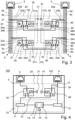
- a network interface 1 shown in Fig. 1 includes printed circuit board (PCB) 2, a first network connector 3, a second network connector 4, a node function unit 10, and a bypass unit 20.
- PCB printed circuit board
- the node function unit 10 includes a first galvanic isolation bridge means 11, a second galvanic isolation bridge means 12, an ethernet switch 13, and a connector 16.
- the node function unit 10 may include a processor (not shown) in addition to the ethernet switch 13 or instead of the ethernet switch 13. In the latter case, the processor as such may include the functionality of the ethernet switch 13.
- the ethernet switch 13 comprises a first ethernet switch port 14 and a second ethernet switch port 15.
- the ethernet switch 13 is functionally coupled with the first network connector 3.
- the ethernet switch 13 (namely the first ethernet switch port 14) is connected to the first network port 3 via the first galvanic isolation bridge means 11.
- the first galvanic isolation bridge means 11 ensures galvanic isolation of the ethernet switch 13 from the first network connector 3 and vice versa but forwards network signals in both directions.
- the ethernet switch 13 is functionally coupled with the second network connector 4.
- the ethernet switch 13 (namely the second ethernet switch port 15) is connected to the second network port 4 via the second galvanic isolation bridge means 12.
- the second galvanic isolation bridge means 12 ensures galvanic isolation of the ethernet switch 13 from the second network connector 4 and vice versa but forwards network signals in both directions.
- the first galvanic isolation bridge means 11 include first magnetic transformer means and/or first capacitive bridge means.
- the second galvanic isolation bridge means 12 include second magnetic transformer means and/or second capacitive bridge means
- the ethernet switch 13 includes a first media-access-control address (MAC) address for the first ethernet switch port 14 (and hence for the first network connector 3) and a second MAC address for the second ethernet switch port 15 (and hence for the second network connector 4).
- MAC media-access-control address
- a connector 16 of the node function unit 10 can be used for connecting the ethernet switch 13 with a processor and/or a microcontroller unit (MCU).
- the connector 16 can be a third port of the ethernet switch 13 or connected thereto.
- the node function unit 10 allows the network interface 1 to constitute a node in a network.
- the network interface 1 can be used in an ethernet network with daisy-chaining, for example in an operation technology network (OT network).
- OT network operation technology network
- the network interface 1 can work as nodes in two different networks.
- the first network connector 3 can be coupled with an external network, such as the internet or a DMZ network
- the second network connector 4 can be coupled with the OT network at the same time.
- the ethernet switch 13 and/or the MCU connected thereto can handle data exchange between the external network and the OT network.
- the bypass unit 20 is configured to enable a direct bypass connection between the first network connector 3 and the second network connector 4 under certain circumstances. If enabled, the bypass connection directly conveys network signals from the first network connector 3 to the second network connector 4 and vice versa, without processing or modifying them. When the bypass connection is enabled, it bypasses or "shortcuts" the node function unit 10 of the network interface 1. It is like if a first network cable connected to the first network connector 3 and a second network cable connected to the second network connector 4 would be replaced by one continuous network cable.
- the bypass unit 20 comprises a monostable switching unit 30 and a bistable switching unit 40, which are directly connected with each other, in this example via bypass conductive traces 21 formed in the PCB 2.
- Fig. 3 shows several individual bypass conductive traces 21a, 21b, 21c, 21d.
- the bypass unit 20 connects the first network connector 3 with the second network connector 4 via the monostable switching unit 30 and the bistable switching unit 40, wherein the monostable switching unit 30 and the bistable switching unit are connected in series in-between the first network connector 3 and the second network connector 4.
- the monostable switching unit 30 is further directly connected to the first network connector 3. In this example, it is connected to the first network connector 3 in parallel with the first galvanic isolation bridge means 11.
- the node function unit 10 - namely the first galvanic isolation bridge means 11 - is directly connected with the first network connector 3 via first conductive traces 5 formed in the PCB 2.
- Fig. 3 shows several individual first conductive traces 5a, 5b, 5c, 5d.
- First branch off traces 23 formed in the PCB 2 connect the monostable switching unit 30 with the first conductive traces 5 or directly with the first network connector 3.
- Fig. 3 shows several individual first branch off traces 23a, 23b, 23c, 23sd.
- bistable switching unit 40 is also directly connected to the second network connector 4 in parallel with the second galvanic isolation bridge means 12.
- the node function unit 10 - namely the second galvanic isolation bridge means 12 - is directly connected with the second network connector 4 via second conductive traces 6 formed in the PCB 2.
- Fig. 3 shows several individual second conductive traces 6a, 6b, 6c, 6d.
- Second branch off traces 24 formed in the PCB 2 connect the bistable switching unit 40 with the second conductive traces 6 or directly with the second network connector 4.
- Fig. 3 shows several individual second branch off traces 24a, 24b, 24c, 24d.
- the number of the individual traces may be the same with regard to the first conductive traces 5, 5a to 5d, the second conductive traces 6, 6a to 6d, the bypass conductive traces 21, 21a to 21d, the first branch off traces 23, 23a to 23d, and the second branch off traces 24, 24a to 24d. Said number may be referred to as trace number.
- the trace number may be 2, 4, or 8, for example.
- the trace number can correspond to N • 2, wherein N is a number of wire pairs of network cables that can be coupled to the first network connector 3 and/or the second network connector 4.
- the bypass unit 20 further comprises a switching input 41 for receiving switching signals for the bistable switching unit 40.
- the bistable switching unit 40 can be switched between two stable states, a breaking state and a connecting state.
- “Bistable” may mean, in this regard, that the switching unit 40 only changes its state when a switching signal is applied. As long as no switching signal is applied, the bistable switching unit 40 remains in the present state, despite of whether the present state is the breaking state or the connecting state.
- the bistable switching unit 40 is also non-volatile. In other words, as long as no switching signal is applied, the bistable switching unit 40 remains in the present state even in the case of complete power failure.
- the bistable switching unit 40 exhibits a "configuration memory" regarding whether it is in the breaking state or in the connecting state.
- bistable switching unit 40 When the bistable switching unit 40 is in the connecting state as shown in Figs. 1 , 3, and 4 , it connects the bypass conductive traces 21 and hence the monostable switching unit 30 directly with second network connector 4.
- the bistable switching unit 40 When the bistable switching unit 40 is in the breaking state as shown in Fig. 2 , it breaks the bypass connection. In more detail, it then disconnects the bypass conductive traces 21 from the second network connector 4.
- current pulses can be used as switching signals for switching the bistable switching unit 40 between the connecting state and the breaking state. This allows to switch between those state via the MCU being connected with the switching input 41. As a result, it is possible to switch between the connecting state and the breaking state by software configuration. As long as no new switching signal is applied, the bistable switching unit 40 will then remain in the present state, independently whether it is the breaking state or the connecting state, even in the case of complete power failure.
- the bypass unit 20 further comprises a condition input 31 for receiving an opening signal for the monostable switching unit 30.
- the switching unit 30 While the opening signal is applied to the monostable switching unit 30, the switching unit 30 is in a non-stable state, which is depicted in Fig. 1 .
- the monostable switching unit 30 In the non-stable state, the monostable switching unit 30 disables the bypass connection between the first network connector 3 and the second network connector 4. In this embodiment, the monostable switching unit 30 disconnects the bypass conductive traces 21 from first network connector 3 when it is in the non-stable state.
- the monostable switching unit 30 While the opening signal is not applied to the monostable switching unit 30, e.g. during power failure and/or during other types of failure of the node function unit 10 (or at least one part thereof), the monostable switching unit 30 is automatically in a stable state.
- the stable state is shown in Figs. 2 , 3, and 4 .
- the monostable switching unit 30 connects the first connector 3 to the bypass conductive traces 21 and hence to the bistable switching unit 40.
- the bistable switching unit 40 is in its connecting state
- the monostable switching unit 30 automatically enables the bypass connection between the first network connector 3 and the second network connector 4 when it is in the stable state.
- the bypass connection extends at least via the first branch off traces 23, 23a to 23d, the monostable switching unit 30, the bypass conductive traces 21, 21a to 21d, the bistable switching unit 40, and the second branch off traces 24, 24a to 24d.
- the opening signal can be, for example, a simple power supply indication. If the power supply to the network interface 1 fails, the node function unit 10 does not work. The ethernet switch 13 cannot send data in this situation. In particular, it cannot forward received network signals, which are bound for other nodes, between the first network connector 3 and the second network connector 4. If the first network connector 3 and the second network connector 4 are coupled to the same network in a daisy-chaining manner, this network is interrupted at the location of the network interface 1 in this situation.
- the bypass connection which is automatically enabled by the monostable switching unit 30 (assumed that the bistable switching unit 40 is in the connecting state), solves this problem - the inactive node function unit 10 is bypassed.
- the bistable switching unit 40 is brought in its breaking state, e.g. due to a corresponding switching signal. While it is in the breaking state, the bistable switching unit 40 prevents that the bypass connection can be enabled.
- the additional bistable switching allows to arbitrarily switch between a first mode, in which the automatic bypass functionality is activated (e.g. as daisy-chaining fallback) and a second mode, in which the automatic bypass functionality is deactivated.
- Fig. 3 shows more details of a possible implementation of the bypass unit 20 in Figs. 1 and 2 .
- the trace number is four and the monostable switching unit 30 comprises two monostable dual pole double throw small signal relays 32, 33 (referred to as monostable DPDT relays 32, 33) whereas the bistable switching unit 40 comprises two bistable double pole double throw small signal relays 42, 43 (referred to as bistable DPDT relays 42, 43).
- Each of the DPDT relays 32, 33, 42, 43 includes two relay terminals 36, 46 and, for each relay terminal 36, 46, two corresponding relay connectors 34a to 34d, 35, 44a to 44d, 45.
- Arrows 37 indicate that the monostable DPDT relays 32, 33 automatically shift to their respective stable state shown in Fig. 3 when the opening signal is no longer applied via the condition input 31 and will automatically remain in the stable state while the opening signal is not applied (again).
- the bistable DPDT relays 42, 43 will change their states only if the switching signal is applied via the switching input 41.
- the relay terminals 36 of the monostable DPDT relays 32, 33 are connected to the first network connector 3 in parallel to the first magnet transfer means 11 (the latter not being shown in Fig. 3 but in Figs. 1 and 2 ).
- the relay terminal 36 one of the two corresponding relay connectors is connected to one of the bypass connection traces 21a, 21b, 21c, 21d - these are referred to as "bypass relay connectors" 34a, 34b, 34c, 34d; the other ones are actually not used in Fig. 3 and are referred to as "dead relay connectors" 35.
- the monostable DPDT relays 32, 33 connect their relay terminals 36 with the bypass relay connectors 34a to 34d in order to enable the bypass connection.
- the monostable DPDT relays 32, 33 connect their relay terminals 36 with the dead relay connectors 35. This disables the bypass connection in any case.
- the relay terminals 46 of the bistable DPDT relays 42, 43 are connected to the second network connector 4 in parallel to the second magnet transfer means 12 (the latter not being shown in Fig. 3 but in Figs. 1 and 2 ).
- the second magnet transfer means 12 the latter not being shown in Fig. 3 but in Figs. 1 and 2 .
- one of the two corresponding relay connectors is connected to one of the bypass connection traces 21a, 21b, 21c, 21d - these are referred to as "bypass relay connectors" 44a, 44b, 44c, 44d; the other ones are not used and are referred to as "dead relay connectors" 45.
- the bistable DPDT relays 42, 43 connect their relay terminals 46 with their bypass relay connectors 44a to 44d.
- the bypass connection can be enabled by the monostable switching unit 30 being in the stable state.
- bistable DPDT relays 42, 43 connect their relay terminals 46 with their dead relay connectors 46.
- the bypass functionality is completely deactivated such that it cannot be enabled by the monostable switching unit 30 being in the stable state.
- the connector 16, the signal input 31, and/or the switching input 41 can use a common hardware connector, e.g. a pin assembly or a female head pin socket (see Fig. 6 ).
- the node function unit 10 - namely the first galvanic isolation bridge means 11 - is connected with the first network connector 3 in series with the monostable switching unit 30.
- the connection between the first network connector 3 and the node function unit 10 (namely the first galvanic isolation bridge means 11) is not needed. Therefore, it is allowed that the monostable switching unit 30 breaks this connection when it is in its stable state.
- the network interface 100 shown in Fig. 4 corresponds to the network interface 1 shown in Fig. 1 and the same reference sings are used.
- Fig. 5 shows an automation controller module 200, including the network interface 1 of Fig. 1 or the modified network interface 100 according to Fig. 4 . Most components are embedded in an interior of a housing 201 of the automation controller module 200. However, the first network connector 3 and the second network connector 4 can be seen in Fig. 5 . In this example, both the first network connector 3 and the second network connector 4 are RJ-45 or GG-45 jacks.
- the automation controller module 200 comprises a plurality input/output (I/O) connectors.
- I/O input/output
- it comprises a plurality of digital I/O connectors 203.
- the I/O connectors 203 are depicted as cable clamps in this embodiment.
- the I/O connectors 203 can be connected to sensors and/or to operational components, e.g. actuators, valves, fans, compressors, fluid mixers, and/or the like.
- the automation controller module 200 is configured to provide control signals (e.g. via the I/O connectors 203) for controlling the operational components based on information received from I/O connectors 203, the first network port 3, and/or the second network port 4.
- the automation controller module 200 is configured to be mounted on a standardized rail 250 for mounting controller modules, e.g. a rail according to IEC/EN 60715.
- the housing 201 comprises a mounting section 202 for mounting the automation controller module 200 onto the rail 250.
- Fig. 6 shows a cross-sectional view of the controller module system 200 mounted on the rail 250 along a longitudinal cross-section plane.
- the automation controller 200 comprises at least one further PCB 207 (actually two in the depicted embodiment).
- the at least one further PCB 207 includes a microcontroller unit 208.
- the at least one further PCB 207 and especially the MCU 208 are connected with the network interface 1, 100.
- the MCU 208 can apply the switching signal to the bistable switching unit 40, allowing to configure via software whether the network interface 1, 100 is in the first mode or in the second mode. Furthermore, the MCU 208 is operatively connected with the ethernet switch 13 such that data can be transferred between the MCU 208 and the first network connector 3 and the second network connector 4.
Landscapes
- Engineering & Computer Science (AREA)
- Computer Networks & Wireless Communication (AREA)
- Signal Processing (AREA)
- Small-Scale Networks (AREA)
Claims (15)
- Netzwerkschnittstelle (1; 100), umfassend:einen ersten Netzwerkverbinder (3);einen zweiten Netzwerkverbinder (4); undeine Verbinder-zu-Verbinder-Bypass-Einheit (20);wobei die Bypass-Einheit (20) eine monostabile Schalteinheit (30) umfasst, um eine Bypass-Verbindung zwischen dem ersten Netzwerkverbinder (3) und dem zweiten Netzwerkverbinder (4) in einem stabilen Zustand zu aktivieren und die Bypass-Verbindung in einem nichtstabilen Zustand zu deaktivieren;dadurch gekennzeichnet, dass die Bypass-Einheit (20) ferner eine bistabile Schalteinheit (40) umfasst, wobei die bistabile Schalteinheit (40) zwischen zwei stabilen Zuständen, nämlich einem Unterbrechungszustand und einem Verbindungszustand, umgeschaltet werden kann, und im Unterbrechungszustand die Bypass-Verbindung unterbricht und im Verbindungszustand die Bypass-Verbindung nicht unterbricht,wobei die monostabile Schalteinheit (30) und die bistabile Schalteinheit (40) in Reihe angeordnet sind und wobei die Bypass-Verbindung nur aktiviert wird während gleichzeitig- die bistabile Schalteinheit (40) in ihrem Verbindungszustand ist und- die monostabile Schalteinheit (30) in ihrem stabilen Zustand ist.
- Netzwerkschnittstelle (1; 100) nach Anspruch 1, wobei die bistabile Schalteinheit (40) mindestens ein bistabiles Relais (42, 43) umfasst.
- Netzwerkschnittstelle (1; 100) nach Anspruch 2, wobei das mindestens eine bistabile Relais (42, 43) ein doppelt umlegendes zweipoliges bistabiles Signalrelais ist.
- Netzwerkschnittstelle (1; 100) nach einem der vorhergehenden Ansprüche, wobei die monostabile Schalteinheit (30) mindestens ein monostabiles Relais (32, 33) umfasst.
- Netzwerkschnittstelle (1; 100) nach Anspruch 4, wobei das mindestens eine monostabile Relais (32, 33) ein doppelt umlegendes zweipoliges monostabiles Signalrelais ist.
- Netzwerkschnittstelle (1; 100) nach einem der vorhergehenden Ansprüche, 10 wobei die Netzwerkschnittstelle (1; 100) so ausgebildet ist, dass die bistabile Schalteinheit (40) durch elektrische Schaltsignale zwischen dem Unterbrechungszustand und einem Verbindungszustand, der die Aktivierung der Bypass-Verbindung durch die monostabile Schalteinheit (30) ermöglicht, umgeschaltet werden kann.
- Netzwerkschnittstelle (1; 100) nach einem der vorhergehenden Ansprüche, wobei die Netzwerkschnittstelle (1; 100) einen Ethernet-Switch (13) umfasst, der funktional mit dem ersten Netzwerkverbinder (3) und dem zweiten Netzwerkverbinder (4) gekoppelt ist.
- Netzwerkschnittstelle (1; 100) nach einem der vorhergehenden Ansprüche, wobei der erste Netzwerkverbinder (3) mindestens eines von dem Folgenden aufweist:• ein RJ-45-Verbinder (3),• ein GG45-Verbinder,• ein RJ-11-Verbinder, 25• ein RJ-22-Verbinder,• ein RS-232-Verbinder und• ein 10Base-T1L-Verbinder.
- Netzwerkschnittstelle (1; 100) nach einem der vorhergehenden Ansprüche, wobei der zweite Netzwerkverbinder (4) mindestens eines von dem Folgenden aufweist:• ein RJ-45-Verbinder (4),• ein GG45-Verbinder,• ein RJ-11-Verbinder,• ein RJ-22-Verbinder,• ein RS-232-Verbinder, und• ein 10Base-T1L-Verbinder.
- Netzwerkschnittstelle (1; 100) nach einem der vorhergehenden Ansprüche, wobei der erste Netzwerkverbinder (3) und der zweite Netzwerkverbinder (4) vom gleichen Typ sind.
- Netzwerkschnittstelle (1; 100) nach einem der vorhergehenden Ansprüche, wobei die Netzwerkschnittstelle (1; 100) erste Brückenmittel (11) zur galvanischen Trennung für den ersten Netzwerkverbinder (3) umfasst, wobei die ersten Brückenmittel (11) zur galvanischen Trennung mit dem ersten Netzwerkverbinder (3)- parallel zur monostabilen Schalteinheit (30) oder- in Reihe über die monostabile Schalteinheit (30) verbunden sind.
- Netzwerkschnittstelle (1; 100) nach einem der vorhergehenden Ansprüche, wobei die Netzwerkschnittstelle (1; 100) zweite Brückenmittel (12) zur galvanischen Trennung für den zweiten Netzwerkverbinder (4) umfasst, wobei die zweiten Brückenmittel (12) zur galvanischen Trennung parallel zur bistabilen Schalteinheit (40) mit dem zweiten Netzwerkverbinder (4) verbunden sind.
- Netzwerkschnittstelle (1; 100) nach einem der vorhergehenden Ansprüche, wobei die Netzwerkschnittstelle (1; 100) eine Leiterplatte (2) aufweist, wobei mindestens der erste Netzwerkverbinder (3), der zweite Netzwerkverbinder (4), die monostabile Schalteinheit (30), und die bistabile Schalteinheit (40) direkt auf der Leiterplatte (2) montiert sind.
- Netzwerkschnittstelle (1; 100) nach einem der vorhergehenden Ansprüche, wobei die Netzwerkschnittstelle (1; 100) einen Verbinder (16, 31, 41) zur Verbindung mit einer Mikrocontrollereinheit (208) umfasst.
- Automatisierungssteuerung (200), aufweisend eine Netzwerkschnittstelle (1; 100) nach einem der vorhergehenden Ansprüche, und- mindestens einen zusätzlichen E/A-Verbinder (203), und/oder- einen Prozessor, und/oder eine Mikrocontrollereinheit (208).
Priority Applications (6)
| Application Number | Priority Date | Filing Date | Title |
|---|---|---|---|
| EP22200658.7A EP4354804B1 (de) | 2022-10-10 | 2022-10-10 | Netzwerkschnittstelle mit deaktivierbarer automatischer bypass-funktionalität zwischen zwei netzwerkverbindern |
| ES22200658T ES2993879T3 (en) | 2022-10-10 | 2022-10-10 | Network interface with deactivatable automatic bypass functionality between two network connectors |
| PL22200658.7T PL4354804T3 (pl) | 2022-10-10 | 2022-10-10 | Interfejs sieciowy z dezaktywowaną funkcjonalnością automatycznego pominięcia pomiędzy dwoma złączami sieciowymi |
| CN202380071700.7A CN120019616A (zh) | 2022-10-10 | 2023-10-06 | 具有位于两个网络连接器之间的可停用自动旁路功能的网络接口 |
| PCT/EP2023/077686 WO2024078983A1 (en) | 2022-10-10 | 2023-10-06 | Network interface with deactivatable automatic bypass functionality between two network connectors |
| EP23785791.7A EP4602771A1 (de) | 2022-10-10 | 2023-10-06 | Netzwerkschnittstelle mit deaktivierbarer automatischer bypass-funktionalität zwischen zwei netzwerkverbindern |
Applications Claiming Priority (1)
| Application Number | Priority Date | Filing Date | Title |
|---|---|---|---|
| EP22200658.7A EP4354804B1 (de) | 2022-10-10 | 2022-10-10 | Netzwerkschnittstelle mit deaktivierbarer automatischer bypass-funktionalität zwischen zwei netzwerkverbindern |
Publications (2)
| Publication Number | Publication Date |
|---|---|
| EP4354804A1 EP4354804A1 (de) | 2024-04-17 |
| EP4354804B1 true EP4354804B1 (de) | 2024-08-07 |
Family
ID=83689858
Family Applications (2)
| Application Number | Title | Priority Date | Filing Date |
|---|---|---|---|
| EP22200658.7A Active EP4354804B1 (de) | 2022-10-10 | 2022-10-10 | Netzwerkschnittstelle mit deaktivierbarer automatischer bypass-funktionalität zwischen zwei netzwerkverbindern |
| EP23785791.7A Pending EP4602771A1 (de) | 2022-10-10 | 2023-10-06 | Netzwerkschnittstelle mit deaktivierbarer automatischer bypass-funktionalität zwischen zwei netzwerkverbindern |
Family Applications After (1)
| Application Number | Title | Priority Date | Filing Date |
|---|---|---|---|
| EP23785791.7A Pending EP4602771A1 (de) | 2022-10-10 | 2023-10-06 | Netzwerkschnittstelle mit deaktivierbarer automatischer bypass-funktionalität zwischen zwei netzwerkverbindern |
Country Status (5)
| Country | Link |
|---|---|
| EP (2) | EP4354804B1 (de) |
| CN (1) | CN120019616A (de) |
| ES (1) | ES2993879T3 (de) |
| PL (1) | PL4354804T3 (de) |
| WO (1) | WO2024078983A1 (de) |
Family Cites Families (3)
| Publication number | Priority date | Publication date | Assignee | Title |
|---|---|---|---|---|
| JPWO2011093012A1 (ja) * | 2010-02-01 | 2013-05-30 | パナソニック株式会社 | ネットワーク装置 |
| WO2014038835A1 (ko) * | 2012-09-05 | 2014-03-13 | 삼성에스디에스 주식회사 | 네트워크 백업 장치 및 이를 구비한 네트워크 시스템 |
| US9240700B2 (en) * | 2012-09-07 | 2016-01-19 | Apple Inc. | Cascading power for accessories |
-
2022
- 2022-10-10 PL PL22200658.7T patent/PL4354804T3/pl unknown
- 2022-10-10 EP EP22200658.7A patent/EP4354804B1/de active Active
- 2022-10-10 ES ES22200658T patent/ES2993879T3/es active Active
-
2023
- 2023-10-06 CN CN202380071700.7A patent/CN120019616A/zh active Pending
- 2023-10-06 WO PCT/EP2023/077686 patent/WO2024078983A1/en not_active Ceased
- 2023-10-06 EP EP23785791.7A patent/EP4602771A1/de active Pending
Also Published As
| Publication number | Publication date |
|---|---|
| PL4354804T3 (pl) | 2024-12-16 |
| CN120019616A (zh) | 2025-05-16 |
| EP4602771A1 (de) | 2025-08-20 |
| EP4354804A1 (de) | 2024-04-17 |
| ES2993879T3 (en) | 2025-01-13 |
| WO2024078983A1 (en) | 2024-04-18 |
Similar Documents
| Publication | Publication Date | Title |
|---|---|---|
| JP4144790B2 (ja) | 構成可能コネクタ化i/oシステム | |
| JP5021037B2 (ja) | マスタ/スレーブ構造を有する通信システム | |
| CN101630298B (zh) | 串行总线从设备地址设置系统 | |
| FI113420B (fi) | Älykäs ohjausjärjestelmä kulkuneuvon virranjakelua varten | |
| US7366115B2 (en) | Multiplex transmission system with in-circuit addressing | |
| WO2007016253A1 (en) | Method device including a bypass switch for an ethernet device, method for creating a bypass path and corresponding ethernet network | |
| EP1320222B1 (de) | Multiplex-Übertragungssystem mit In-Circuit-Adressierung- | |
| US12189448B2 (en) | Modular power controller | |
| CN102160253B (zh) | 用于开关设备控制的功能模块和耦合模块以及用于开关设备控制的系统 | |
| US7061926B2 (en) | Method and apparatus for a network bus topology | |
| CN102918809B (zh) | 网络和扩展单元以及运行网络的方法 | |
| EP4354804B1 (de) | Netzwerkschnittstelle mit deaktivierbarer automatischer bypass-funktionalität zwischen zwei netzwerkverbindern | |
| US20090116405A1 (en) | Redundant Automation Data Communications Network | |
| US6928584B2 (en) | Segmented protection system and method | |
| EP2936328B1 (de) | Elektrischer knoten für daisy-chain-schienen mit serieller datenübertragung und gleichzeitiger übertragung elektrischer energie | |
| US20110232965A1 (en) | Terminating Unit and Programmable Controller | |
| EP3217603B1 (de) | Kommunikationsvorrichtung mit relais | |
| JPH11168488A (ja) | ハブ切換装置、これを用いた配線システム及びハブ切換装置の使用方法 | |
| CA2350346A1 (en) | Method and apparatus for electrically terminating a transmission bus for a communication network | |
| CN115699687A (zh) | 用于具有至少两个传输线路的总线系统的控制系统 | |
| US6647537B1 (en) | IEEE 1394 cable connector with short circuit switch | |
| EP2869498B1 (de) | Netzwerkverwaltungssystem | |
| KR200379364Y1 (ko) | 디지털 보호 계전기의 선로 이중화 기능을 갖는 통신모듈 장치 | |
| KR20040043872A (ko) | 론워크 및 아이피에스를 이용한 버스용 룸램프 제어 방법 | |
| JP2002247061A (ja) | ネットワーク端末及びネットワーク端末の制御方法 |
Legal Events
| Date | Code | Title | Description |
|---|---|---|---|
| PUAI | Public reference made under article 153(3) epc to a published international application that has entered the european phase |
Free format text: ORIGINAL CODE: 0009012 |
|
| STAA | Information on the status of an ep patent application or granted ep patent |
Free format text: STATUS: REQUEST FOR EXAMINATION WAS MADE |
|
| 17P | Request for examination filed |
Effective date: 20230516 |
|
| AK | Designated contracting states |
Kind code of ref document: A1 Designated state(s): AL AT BE BG CH CY CZ DE DK EE ES FI FR GB GR HR HU IE IS IT LI LT LU LV MC ME MK MT NL NO PL PT RO RS SE SI SK SM TR |
|
| GRAP | Despatch of communication of intention to grant a patent |
Free format text: ORIGINAL CODE: EPIDOSNIGR1 |
|
| STAA | Information on the status of an ep patent application or granted ep patent |
Free format text: STATUS: GRANT OF PATENT IS INTENDED |
|
| RBV | Designated contracting states (corrected) |
Designated state(s): AL AT BE BG CH CY CZ DE DK EE ES FI FR GB GR HR HU IE IS IT LI LT LU LV MC ME MK MT NL NO PL PT RO RS SE SI SK SM TR |
|
| INTG | Intention to grant announced |
Effective date: 20240426 |
|
| GRAS | Grant fee paid |
Free format text: ORIGINAL CODE: EPIDOSNIGR3 |
|
| GRAA | (expected) grant |
Free format text: ORIGINAL CODE: 0009210 |
|
| STAA | Information on the status of an ep patent application or granted ep patent |
Free format text: STATUS: THE PATENT HAS BEEN GRANTED |
|
| P01 | Opt-out of the competence of the unified patent court (upc) registered |
Free format text: CASE NUMBER: APP_33702/2024 Effective date: 20240605 |
|
| AK | Designated contracting states |
Kind code of ref document: B1 Designated state(s): AL AT BE BG CH CY CZ DE DK EE ES FI FR GB GR HR HU IE IS IT LI LT LU LV MC ME MK MT NL NO PL PT RO RS SE SI SK SM TR |
|
| REG | Reference to a national code |
Ref country code: GB Ref legal event code: FG4D |
|
| REG | Reference to a national code |
Ref country code: CH Ref legal event code: EP |
|
| REG | Reference to a national code |
Ref country code: IE Ref legal event code: FG4D |
|
| REG | Reference to a national code |
Ref country code: DE Ref legal event code: R096 Ref document number: 602022005143 Country of ref document: DE |
|
| REG | Reference to a national code |
Ref country code: SE Ref legal event code: TRGR |
|
| REG | Reference to a national code |
Ref country code: NL Ref legal event code: FP |
|
| REG | Reference to a national code |
Ref country code: LT Ref legal event code: MG9D |
|
| REG | Reference to a national code |
Ref country code: ES Ref legal event code: FG2A Ref document number: 2993879 Country of ref document: ES Kind code of ref document: T3 Effective date: 20250113 |
|
| PG25 | Lapsed in a contracting state [announced via postgrant information from national office to epo] |
Ref country code: NO Free format text: LAPSE BECAUSE OF FAILURE TO SUBMIT A TRANSLATION OF THE DESCRIPTION OR TO PAY THE FEE WITHIN THE PRESCRIBED TIME-LIMIT Effective date: 20241107 |
|
| PG25 | Lapsed in a contracting state [announced via postgrant information from national office to epo] |
Ref country code: FI Free format text: LAPSE BECAUSE OF FAILURE TO SUBMIT A TRANSLATION OF THE DESCRIPTION OR TO PAY THE FEE WITHIN THE PRESCRIBED TIME-LIMIT Effective date: 20240807 Ref country code: GR Free format text: LAPSE BECAUSE OF FAILURE TO SUBMIT A TRANSLATION OF THE DESCRIPTION OR TO PAY THE FEE WITHIN THE PRESCRIBED TIME-LIMIT Effective date: 20241108 Ref country code: PT Free format text: LAPSE BECAUSE OF FAILURE TO SUBMIT A TRANSLATION OF THE DESCRIPTION OR TO PAY THE FEE WITHIN THE PRESCRIBED TIME-LIMIT Effective date: 20241209 |
|
| PG25 | Lapsed in a contracting state [announced via postgrant information from national office to epo] |
Ref country code: BG Free format text: LAPSE BECAUSE OF FAILURE TO SUBMIT A TRANSLATION OF THE DESCRIPTION OR TO PAY THE FEE WITHIN THE PRESCRIBED TIME-LIMIT Effective date: 20240807 |
|
| PG25 | Lapsed in a contracting state [announced via postgrant information from national office to epo] |
Ref country code: LV Free format text: LAPSE BECAUSE OF FAILURE TO SUBMIT A TRANSLATION OF THE DESCRIPTION OR TO PAY THE FEE WITHIN THE PRESCRIBED TIME-LIMIT Effective date: 20240807 |
|
| PG25 | Lapsed in a contracting state [announced via postgrant information from national office to epo] |
Ref country code: IS Free format text: LAPSE BECAUSE OF FAILURE TO SUBMIT A TRANSLATION OF THE DESCRIPTION OR TO PAY THE FEE WITHIN THE PRESCRIBED TIME-LIMIT Effective date: 20241207 |
|
| PG25 | Lapsed in a contracting state [announced via postgrant information from national office to epo] |
Ref country code: HR Free format text: LAPSE BECAUSE OF FAILURE TO SUBMIT A TRANSLATION OF THE DESCRIPTION OR TO PAY THE FEE WITHIN THE PRESCRIBED TIME-LIMIT Effective date: 20240807 |
|
| PG25 | Lapsed in a contracting state [announced via postgrant information from national office to epo] |
Ref country code: RS Free format text: LAPSE BECAUSE OF FAILURE TO SUBMIT A TRANSLATION OF THE DESCRIPTION OR TO PAY THE FEE WITHIN THE PRESCRIBED TIME-LIMIT Effective date: 20241107 |
|
| PG25 | Lapsed in a contracting state [announced via postgrant information from national office to epo] |
Ref country code: RS Free format text: LAPSE BECAUSE OF FAILURE TO SUBMIT A TRANSLATION OF THE DESCRIPTION OR TO PAY THE FEE WITHIN THE PRESCRIBED TIME-LIMIT Effective date: 20241107 Ref country code: PT Free format text: LAPSE BECAUSE OF FAILURE TO SUBMIT A TRANSLATION OF THE DESCRIPTION OR TO PAY THE FEE WITHIN THE PRESCRIBED TIME-LIMIT Effective date: 20241209 Ref country code: NO Free format text: LAPSE BECAUSE OF FAILURE TO SUBMIT A TRANSLATION OF THE DESCRIPTION OR TO PAY THE FEE WITHIN THE PRESCRIBED TIME-LIMIT Effective date: 20241107 Ref country code: LV Free format text: LAPSE BECAUSE OF FAILURE TO SUBMIT A TRANSLATION OF THE DESCRIPTION OR TO PAY THE FEE WITHIN THE PRESCRIBED TIME-LIMIT Effective date: 20240807 Ref country code: IS Free format text: LAPSE BECAUSE OF FAILURE TO SUBMIT A TRANSLATION OF THE DESCRIPTION OR TO PAY THE FEE WITHIN THE PRESCRIBED TIME-LIMIT Effective date: 20241207 Ref country code: HR Free format text: LAPSE BECAUSE OF FAILURE TO SUBMIT A TRANSLATION OF THE DESCRIPTION OR TO PAY THE FEE WITHIN THE PRESCRIBED TIME-LIMIT Effective date: 20240807 Ref country code: GR Free format text: LAPSE BECAUSE OF FAILURE TO SUBMIT A TRANSLATION OF THE DESCRIPTION OR TO PAY THE FEE WITHIN THE PRESCRIBED TIME-LIMIT Effective date: 20241108 Ref country code: FI Free format text: LAPSE BECAUSE OF FAILURE TO SUBMIT A TRANSLATION OF THE DESCRIPTION OR TO PAY THE FEE WITHIN THE PRESCRIBED TIME-LIMIT Effective date: 20240807 Ref country code: BG Free format text: LAPSE BECAUSE OF FAILURE TO SUBMIT A TRANSLATION OF THE DESCRIPTION OR TO PAY THE FEE WITHIN THE PRESCRIBED TIME-LIMIT Effective date: 20240807 |
|
| PG25 | Lapsed in a contracting state [announced via postgrant information from national office to epo] |
Ref country code: DK Free format text: LAPSE BECAUSE OF FAILURE TO SUBMIT A TRANSLATION OF THE DESCRIPTION OR TO PAY THE FEE WITHIN THE PRESCRIBED TIME-LIMIT Effective date: 20240807 Ref country code: SM Free format text: LAPSE BECAUSE OF FAILURE TO SUBMIT A TRANSLATION OF THE DESCRIPTION OR TO PAY THE FEE WITHIN THE PRESCRIBED TIME-LIMIT Effective date: 20240807 |
|
| PG25 | Lapsed in a contracting state [announced via postgrant information from national office to epo] |
Ref country code: EE Free format text: LAPSE BECAUSE OF FAILURE TO SUBMIT A TRANSLATION OF THE DESCRIPTION OR TO PAY THE FEE WITHIN THE PRESCRIBED TIME-LIMIT Effective date: 20240807 |
|
| PG25 | Lapsed in a contracting state [announced via postgrant information from national office to epo] |
Ref country code: CZ Free format text: LAPSE BECAUSE OF FAILURE TO SUBMIT A TRANSLATION OF THE DESCRIPTION OR TO PAY THE FEE WITHIN THE PRESCRIBED TIME-LIMIT Effective date: 20240807 |
|
| PG25 | Lapsed in a contracting state [announced via postgrant information from national office to epo] |
Ref country code: SK Free format text: LAPSE BECAUSE OF FAILURE TO SUBMIT A TRANSLATION OF THE DESCRIPTION OR TO PAY THE FEE WITHIN THE PRESCRIBED TIME-LIMIT Effective date: 20240807 |
|
| REG | Reference to a national code |
Ref country code: DE Ref legal event code: R097 Ref document number: 602022005143 Country of ref document: DE |
|
| PLBE | No opposition filed within time limit |
Free format text: ORIGINAL CODE: 0009261 |
|
| STAA | Information on the status of an ep patent application or granted ep patent |
Free format text: STATUS: NO OPPOSITION FILED WITHIN TIME LIMIT |
|
| PG25 | Lapsed in a contracting state [announced via postgrant information from national office to epo] |
Ref country code: MC Free format text: LAPSE BECAUSE OF FAILURE TO SUBMIT A TRANSLATION OF THE DESCRIPTION OR TO PAY THE FEE WITHIN THE PRESCRIBED TIME-LIMIT Effective date: 20240807 |
|
| PG25 | Lapsed in a contracting state [announced via postgrant information from national office to epo] |
Ref country code: BE Free format text: LAPSE BECAUSE OF NON-PAYMENT OF DUE FEES Effective date: 20241031 Ref country code: LU Free format text: LAPSE BECAUSE OF NON-PAYMENT OF DUE FEES Effective date: 20241010 |
|
| 26N | No opposition filed |
Effective date: 20250508 |
|
| REG | Reference to a national code |
Ref country code: BE Ref legal event code: MM Effective date: 20241031 |
|
| PGFP | Annual fee paid to national office [announced via postgrant information from national office to epo] |
Ref country code: PL Payment date: 20250912 Year of fee payment: 4 Ref country code: NL Payment date: 20250912 Year of fee payment: 4 |
|
| PGFP | Annual fee paid to national office [announced via postgrant information from national office to epo] |
Ref country code: FR Payment date: 20250908 Year of fee payment: 4 |
|
| PGFP | Annual fee paid to national office [announced via postgrant information from national office to epo] |
Ref country code: SE Payment date: 20250910 Year of fee payment: 4 |
|
| PG25 | Lapsed in a contracting state [announced via postgrant information from national office to epo] |
Ref country code: IE Free format text: LAPSE BECAUSE OF NON-PAYMENT OF DUE FEES Effective date: 20241010 |
|
| REG | Reference to a national code |
Ref country code: CH Ref legal event code: U11 Free format text: ST27 STATUS EVENT CODE: U-0-0-U10-U11 (AS PROVIDED BY THE NATIONAL OFFICE) Effective date: 20251101 |
|
| PG25 | Lapsed in a contracting state [announced via postgrant information from national office to epo] |
Ref country code: RO Free format text: LAPSE BECAUSE OF FAILURE TO SUBMIT A TRANSLATION OF THE DESCRIPTION OR TO PAY THE FEE WITHIN THE PRESCRIBED TIME-LIMIT Effective date: 20240807 |
|
| PGFP | Annual fee paid to national office [announced via postgrant information from national office to epo] |
Ref country code: DE Payment date: 20250902 Year of fee payment: 4 |
|
| PGFP | Annual fee paid to national office [announced via postgrant information from national office to epo] |
Ref country code: AT Payment date: 20260113 Year of fee payment: 4 |
|
| PGFP | Annual fee paid to national office [announced via postgrant information from national office to epo] |
Ref country code: IT Payment date: 20251031 Year of fee payment: 4 |
|
| PG25 | Lapsed in a contracting state [announced via postgrant information from national office to epo] |
Ref country code: IT Free format text: LAPSE BECAUSE OF NON-PAYMENT OF DUE FEES Effective date: 20241010 |
|
| PGFP | Annual fee paid to national office [announced via postgrant information from national office to epo] |
Ref country code: TR Payment date: 20251003 Year of fee payment: 4 |
|
| PGFP | Annual fee paid to national office [announced via postgrant information from national office to epo] |
Ref country code: CH Payment date: 20251101 Year of fee payment: 4 |
|
| PG25 | Lapsed in a contracting state [announced via postgrant information from national office to epo] |
Ref country code: CY Free format text: LAPSE BECAUSE OF FAILURE TO SUBMIT A TRANSLATION OF THE DESCRIPTION OR TO PAY THE FEE WITHIN THE PRESCRIBED TIME-LIMIT; INVALID AB INITIO Effective date: 20221010 |
|
| PGFP | Annual fee paid to national office [announced via postgrant information from national office to epo] |
Ref country code: ES Payment date: 20251107 Year of fee payment: 4 |
|
| PG25 | Lapsed in a contracting state [announced via postgrant information from national office to epo] |
Ref country code: HU Free format text: LAPSE BECAUSE OF FAILURE TO SUBMIT A TRANSLATION OF THE DESCRIPTION OR TO PAY THE FEE WITHIN THE PRESCRIBED TIME-LIMIT; INVALID AB INITIO Effective date: 20221010 |
|
| PG25 | Lapsed in a contracting state [announced via postgrant information from national office to epo] |
Ref country code: IT Free format text: LAPSE BECAUSE OF NON-PAYMENT OF DUE FEES Effective date: 20241010 |
|
| PGRI | Patent reinstated in contracting state [announced from national office to epo] |
Ref country code: IT Effective date: 20241031 |