EP4354986A1 - Procédé de mesure de retard de transmission, procédé de positionnement, terminal, station de base et support de stockage - Google Patents
Procédé de mesure de retard de transmission, procédé de positionnement, terminal, station de base et support de stockage Download PDFInfo
- Publication number
- EP4354986A1 EP4354986A1 EP22815026.4A EP22815026A EP4354986A1 EP 4354986 A1 EP4354986 A1 EP 4354986A1 EP 22815026 A EP22815026 A EP 22815026A EP 4354986 A1 EP4354986 A1 EP 4354986A1
- Authority
- EP
- European Patent Office
- Prior art keywords
- path
- base station
- uplink
- delay
- transmission delay
- Prior art date
- Legal status (The legal status is an assumption and is not a legal conclusion. Google has not performed a legal analysis and makes no representation as to the accuracy of the status listed.)
- Pending
Links
Images







Classifications
-
- H—ELECTRICITY
- H04—ELECTRIC COMMUNICATION TECHNIQUE
- H04B—TRANSMISSION
- H04B17/00—Monitoring; Testing
- H04B17/30—Monitoring; Testing of propagation channels
- H04B17/309—Measuring or estimating channel quality parameters
- H04B17/364—Delay profiles
-
- H—ELECTRICITY
- H04—ELECTRIC COMMUNICATION TECHNIQUE
- H04W—WIRELESS COMMUNICATION NETWORKS
- H04W24/00—Supervisory, monitoring or testing arrangements
- H04W24/10—Scheduling measurement reports ; Arrangements for measurement reports
-
- G—PHYSICS
- G01—MEASURING; TESTING
- G01S—RADIO DIRECTION-FINDING; RADIO NAVIGATION; DETERMINING DISTANCE OR VELOCITY BY USE OF RADIO WAVES; LOCATING OR PRESENCE-DETECTING BY USE OF THE REFLECTION OR RERADIATION OF RADIO WAVES; ANALOGOUS ARRANGEMENTS USING OTHER WAVES
- G01S13/00—Systems using the reflection or reradiation of radio waves, e.g. radar systems; Analogous systems using reflection or reradiation of waves whose nature or wavelength is irrelevant or unspecified
- G01S13/74—Systems using reradiation of radio waves, e.g. secondary radar systems; Analogous systems
- G01S13/76—Systems using reradiation of radio waves, e.g. secondary radar systems; Analogous systems wherein pulse-type signals are transmitted
- G01S13/765—Systems using reradiation of radio waves, e.g. secondary radar systems; Analogous systems wherein pulse-type signals are transmitted with exchange of information between interrogator and responder
-
- H—ELECTRICITY
- H04—ELECTRIC COMMUNICATION TECHNIQUE
- H04B—TRANSMISSION
- H04B17/00—Monitoring; Testing
- H04B17/10—Monitoring; Testing of transmitters
- H04B17/101—Monitoring; Testing of transmitters for measurement of specific parameters of the transmitter or components thereof
- H04B17/104—Monitoring; Testing of transmitters for measurement of specific parameters of the transmitter or components thereof of other parameters, e.g. DC offset, delay or propagation times
-
- H—ELECTRICITY
- H04—ELECTRIC COMMUNICATION TECHNIQUE
- H04B—TRANSMISSION
- H04B17/00—Monitoring; Testing
- H04B17/20—Monitoring; Testing of receivers
- H04B17/24—Monitoring; Testing of receivers with feedback of measurements to the transmitter
-
- H—ELECTRICITY
- H04—ELECTRIC COMMUNICATION TECHNIQUE
- H04B—TRANSMISSION
- H04B17/00—Monitoring; Testing
- H04B17/30—Monitoring; Testing of propagation channels
- H04B17/309—Measuring or estimating channel quality parameters
- H04B17/318—Received signal strength
- H04B17/328—Reference signal received power [RSRP]; Reference signal received quality [RSRQ]
-
- H—ELECTRICITY
- H04—ELECTRIC COMMUNICATION TECHNIQUE
- H04L—TRANSMISSION OF DIGITAL INFORMATION, e.g. TELEGRAPHIC COMMUNICATION
- H04L43/00—Arrangements for monitoring or testing data switching networks
- H04L43/08—Monitoring or testing based on specific metrics, e.g. QoS, energy consumption or environmental parameters
- H04L43/0852—Delays
-
- H—ELECTRICITY
- H04—ELECTRIC COMMUNICATION TECHNIQUE
- H04L—TRANSMISSION OF DIGITAL INFORMATION, e.g. TELEGRAPHIC COMMUNICATION
- H04L43/00—Arrangements for monitoring or testing data switching networks
- H04L43/08—Monitoring or testing based on specific metrics, e.g. QoS, energy consumption or environmental parameters
- H04L43/0852—Delays
- H04L43/0864—Round trip delays
-
- H—ELECTRICITY
- H04—ELECTRIC COMMUNICATION TECHNIQUE
- H04L—TRANSMISSION OF DIGITAL INFORMATION, e.g. TELEGRAPHIC COMMUNICATION
- H04L5/00—Arrangements affording multiple use of the transmission path
- H04L5/003—Arrangements for allocating sub-channels of the transmission path
- H04L5/0048—Allocation of pilot signals, i.e. of signals known to the receiver
-
- H—ELECTRICITY
- H04—ELECTRIC COMMUNICATION TECHNIQUE
- H04W—WIRELESS COMMUNICATION NETWORKS
- H04W24/00—Supervisory, monitoring or testing arrangements
- H04W24/08—Testing, supervising or monitoring using real traffic
-
- H—ELECTRICITY
- H04—ELECTRIC COMMUNICATION TECHNIQUE
- H04W—WIRELESS COMMUNICATION NETWORKS
- H04W64/00—Locating users or terminals or network equipment for network management purposes, e.g. mobility management
Definitions
- the present disclosure relates to, but is not limited to, the field of wireless communication, and in particular to a method for measuring transmission delay, a method for positioning, a terminal device, a base station, and a storage medium.
- Ranging is a key link in the positioning function, which is typically achieved by measuring the transmission delay between a transmitter and a receiver. Due to inefficiencies of the current commercial base stations and terminal devices in maintaining a high degree of consistency in time reference, the International Organization for Standardization puts forward Round Trip Time (RTT) measurement in relevant standards.
- RTT Round Trip Time
- Line of Sight path is a transmission path with no reflection of the transmission signals, so the transmission delay of the LOS path constitutes key information for RTT measurement.
- the reference signal transmitted through the LOS path is prone to submergence by sidelobes, noise, or interference of the non-light-of-sight (NLOS) path.
- the terminal device would consecutively transmit multiple uplink reference signals to improve the signal noise ratio (SNR) of the signals to be received by the base station, so as to detect the LOS path and measure the uplink transmission delay of the LOS path.
- SNR signal noise ratio
- a method for measuring transmission delay a method for positioning, a terminal device, a base station, and a storage medium, which can achieve the measurement of the uplink transmission delay of a LOS path with less resource overhead under the condition of low transmission power of the terminal device.
- An embodiment of the present disclosure provides a method for measuring transmission delay, which is applied to a terminal device.
- the method includes,
- An embodiment of the present disclosure provides a method for measuring transmission delay, which is applied to a base station.
- the method includes,
- An embodiment of the present disclosure provides a method for positioning, which is applied to a positioning server in communicative connection with a base station and a terminal device respectively.
- the method includes,
- An embodiment of the present disclosure provides a terminal device, which includes a memory, a processor, and a computer program stored in the memory and executable by the processor which, when executed by the processor causes the processor to carry out the method which is applied to the terminal device as described above.
- An embodiment of the present disclosure provides a base station, which includes a memory, a processor, and a computer program stored in the memory and executable by the processor which, when executed by the processor causes the processor to carry out the method that is applied to the base station as described above.
- Some embodiments of the present disclosure provide a method for measuring transmission delay, a method for positioning, a terminal device, a base station, and a storage medium.
- the method for measuring transmission delay includes, acquiring a downlink reference signal sent by a base station, and determining a line of sight (LOS) path and a reference path from a plurality of transmission paths of the downlink reference signal; acquiring a reference delay difference that is a difference between a downlink transmission delay of the LOS path and the downlink transmission delay of the reference path; sending an uplink reference signal to the base station, to cause the base station to obtain an uplink transmission delay of the reference path based on the uplink reference signal; and reporting the reference delay difference to the base station, to cause the base station to obtain the uplink transmission delay of the LOS path based on the uplink transmission delay of the reference path and the reference delay difference.
- LOS line of sight
- the base station is enabled to obtain the uplink transmission delay of the reference path through one uplink reference signal, and the uplink transmission delay of the LOS path is calculated through the uplink transmission delay of the reference path in conjunction with the reference delay difference, thus effectively reducing the resource overhead for measuring the uplink transmission delay of the LOS path.
- the base station can directly extract the signal corresponding to the LOS path from the transmission signal, and the method according to an embodiment of the present disclosure is still applicable to calculate the parameters of the LOS path in conjunction with the reference delay difference and the parameters of the reference path, which will not limit the technical scheme of the present disclosure.
- FIG. 1 depicts a flowchart showing a method for measuring transmission delay according to an embodiment of the present disclosure. The method is applied to a terminal device, and includes but is not limited to operations S110, S120, S130 and S 140.
- a downlink reference signal sent by a base station is acquired, and a Line of Sight (LOS) path and a reference path are determined from the transmission paths of the downlink reference signal.
- LOS Line of Sight
- the downlink reference signal can be a downlink positioning reference signal for positioning.
- Other types of signals can be employed, provided that the terminal device is allowed to determine each transmission path based on the downlink reference signal.
- Those having ordinary skills in the art can conceive selecting a particular type of signal based on the practical requirement. This embodiment is not limited thereto.
- the terminal device can directly determine the LOS path from the transmission paths of the downlink reference signal in any way. This embodiment does not limit the methods that the terminal device employs to determine the LOS path.
- the reference path can be any path other than the LOS path.
- the selection of the reference path is intended to calculate the parameters of the LOS path by means of the parameters of the reference path in conjunction with the reference delay difference, and on the basis that the uplink path and the downlink path are identical. It is apparent that, the identical uplink and downlink paths can be achieved by employing the identical transmitting and receiving beams, and the present disclosure does not limit the beams.
- the signal transmission of the LOS path will be affected by factors such as transmission environment and interference. If the transmission power of the terminal device is increased, the signal power of the LOS path and the interference signal will increase in equal proportion. If the number of uplink reference signals is increased, the resource overhead will increase. Moreover, under the condition that the SNR of the transmission signal of the LOS path is extremely low, even if the number of uplink reference signals is increased, it may be inefficient for the base station to detect the transmission signal of the LOS path. Based on this, a reference path is introduced in this embodiment. The uplink transmission delay of the LOS path is calculated through the reference delay difference between the reference path and the LOS path, which can not only save resource overhead, but also eliminate direct measurements by calculation. Even if the SNR is extremely low, the uplink transmission delay of the LOS path can be accurately obtained.
- the base station can directly measure the uplink transmission delay.
- the technical scheme set forth in an embodiment of the present disclosure can be adopted to calculate the uplink transmission delay of the LOS path through the reference delay difference between the LOS path and the reference path, so that the measurement can be transformed into a calculation to ensure that the uplink transmission delay of the LOS path can be accurately obtained.
- Those having ordinary skills in the art can conceive presetting the acquisition scheme of the uplink transmission delay of the LOS path at the base station, and the terminal device only needs to send the corresponding uplink reference signal based on the acquisition scheme set by the base station, while this embodiment is not limited thereto.
- a reference delay difference which is the difference between the downlink transmission delay of the LOS path and the downlink transmission delay of the reference path, is acquired.
- the reference delay difference can be the difference obtained by subtracting the downlink transmission delay of the reference path from the downlink transmission delay of the LOS path. Since the uplink transmission path and the downlink transmission path can be identical, the reference delay difference at the terminal device side is identical to the reference delay difference at the base station side. Based on this, the reference delay difference is calculated at the terminal device side by means of the strong signal power of the downlink reference signal received by the terminal device. Even if the signal power received by the base station is weak, the uplink transmission delay of the LOS path can be calculated by measuring the uplink reference delay of the reference path in conjunction with the reference delay difference.
- the uplink transmission delay of the LOS path can be obtained with at least one reference delay difference and one uplink reference signal which enables the base station to identify the reference path, thus effectively reducing the required number of transmissions of uplink reference signals in RTT measurement and saving the resource overhead.
- an uplink reference signal is sent to the base station, to cause the base station to obtain the uplink transmission delay of the reference path based on the uplink reference signal.
- the uplink reference signal may be an uplink positioning reference signal for positioning, such as a common SRS, and this embodiment does not specifically limit this.
- the base station can measure the uplink transmission delay of the reference path
- the transmission path with the strongest signal power can be taken as the reference path.
- the uplink transmission delay can be measured in any way, and this embodiment does not limit this.
- the terminal device since the reference path is selected by the terminal device from the transmission paths, the reference path is unknown to the base station. As a consequence, the terminal device and the base station can make an agreement in advance on the scheme of identification for the reference path, in which, for example, same beam is set in advance through configuration information, and the path with the strongest signal power is taken as the reference path, this embodiment does not specifically limit this.
- the reference delay difference is reported to the base station, to cause the base station can obtain the uplink transmission delay of the LOS path based on the uplink transmission delay of the reference path, and the reference delay difference.
- the uplink transmission delay of the LOS path can be measured by employing the principle that the reference delay difference of the transmission path is identical at both transmitting and receiving ends.
- the base station obtains and takes the sum of the uplink transmission delay of the reference path and the reference delay difference, as the uplink transmission delay of the LOS path.
- the reference delay difference can be reported in an appropriate scheme based on the practical requirements. Those having ordinary skills in the art are able to determine a particular scheme for reporting by modifying the configuration information of the equipment. For example, in the case of sufficient signaling resources, the terminal device is configured through the configuration information to report through additional signaling interaction, and the reference delay difference is directly informed to the base station. With this technical scheme, only one uplink reference signal is needed to be sent to the base station, so that the base station can determine the uplink transmission delay of the reference path, and in turn obtain the uplink transmission delay of the LOS path, which is beneficial to saving the resource overhead caused by the transmission of the uplink reference signal.
- the base station pre-configure the base station with a scheme in that an uplink reference signal is employed to carry the reference delay difference for reporting.
- one uplink reference signal is modulated based on the reference delay difference.
- the base station After receiving the uplink reference signal modulated based on the reference delay difference, the base station can obtain the reference delay difference by measuring the difference of reference paths reflected in the two uplink reference signals.
- the uplink transmission delay of the LOS path can be measured by the transmission of only two uplink reference signals, which effectively reduces the resource overhead.
- S 110 in the embodiment shown in conjunction with FIG. 1 further includes, but is not limited to, the following operations.
- the transmission path that completes the downlink reference signal transmission at the earliest is determined as the LOS path.
- the signal reception power of the transmission path of the downlink reference signal is determined, and the reference path is determined based on the signal reception power, where the signal reception power of the reference path is greater than or equal to the signal reception power of the LOS path.
- the LOS path is a transmission path with no reflection of the transmission signals, it can be clear that the downlink reference signal transmitted will reach the terminal device earliest through the LOS path.
- the transmission power of the base station is typically sufficient, and thus it is not likely that the transmission signal of the LOS path is submerged by noise, so it can be determined that the transmission path of the earliest received downlink transmission signal is the LOS path.
- the reference path may be any path other than the LOS path, for example, the path with the strongest signal power is selected for ease of identification, or the weighted transmission path of all transmission paths is taken as the reference path.
- the weighted transmission path of all transmission paths described above may be obtained by multiplying the delay of each transmission path by the signal power, and the obtained value is summed up and then divided by the sum of the signal power of all the transmission paths to obtain a virtual path.
- the specific scheme of selection of the reference path may be determined in accordance with the specific conditions of the transmission signal. It can be understood that in order to reduce the resource overhead, only one transmission path may be selected as the reference path. It is apparent that, the number of reference paths can be appropriately increased under the condition of sufficient resources, so as to improve the accuracy of data measurement, this embodiment does not limit this.
- the uplink reference signal is the Sounding Reference Symbol (SRS).
- SRS Sounding Reference Symbol
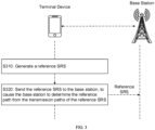
- a reference SRS is generated.
- the reference SRS is sent to the base station, to cause the base station to determine the reference path from the transmission path of the reference SRS.
- the uplink reference signal is SRS.
- the SRS can be generated by means of the SRS configuration method specified in the existing protocol or standard and sent, so that the time delay obtained by the base station through the reference SRS is the real-time delay.
- the reference SRS provides a reference for the subsequent uplink transmission delay calculation of the LOS path.
- S140 in the embodiment shown in conjunction with FIG. 1 further includes, but is not limited to, the following operations.
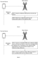
- a new reference SRS is generated, and the new reference SRS is modulated based on the reference delay difference to obtain a modulated SRS.
- the modulated SRS is sent to the base station, to cause the base station can obtain the reference delay difference based on the modulated SRS and the reference SRS, and obtain the uplink transmission delay of the LOS path based on the uplink transmission delay of the reference path, and the reference delay difference.
- the identification scheme of reference SRS and modulated SRS may be preset in the base station.
- the terminal device sends two consecutive OFDM symbols to the base station in one time slot, in which the SRS on the first received OFDM symbol is the reference SRS, and the SRS on the second received OFDM symbol is the modulated SRS.
- the SRS on the first received OFDM symbol is the reference SRS
- the SRS on the second received OFDM symbol is the modulated SRS.
- modulation can be performed based on the reference SRS.
- the reference SRS can reflect the real delay of uplink transmission
- the delay received by the receiving end can generate some deviations, and the generated deviation is related to the reference delay difference.
- the acquisition of the reference delay difference can be transformed into the acquisition of the difference between symbols.
- the terminal device only needs to send SRS over two symbols to the base station. That is, the calculation of the uplink transmission delay of the LOS path can be realized, even if the transmission power of the terminal device is weak, since the transmission path with the strongest signal power is selected as the reference path, the difference of the reference path between two symbols can be obtained, so the transmission of multiple uplink reference signals is not necessary, which effectively saves resources.
- the reference delay difference based on the reference SRS and the modulated SRS can be obtained by channel feature estimation.
- a case where both transmitting and receiving ends employ an identical transmitting beam and receiving beam is illustrated below.
- the uplink reference delay of the reference path which can be denoted such as ⁇ BS,ref , can be estimated by means of Fourier transform.
- ⁇ los,ref ( ⁇ BS,ref - ⁇ BS,non-ref )/ ⁇ .
- the acquisition of the reference delay difference can be transformed into the calculation of ⁇ BS,ref - ⁇ BS,non-ref , i.e., the uplink transmission delay of the reference SRS and the modulated SRS in the reference path. Since the reference path is the transmission path with the strongest signal power, the measurement of the uplink transmission delay for the reference path is relatively simple. As such, the calculation of uplink transmission delay of LOS path is achieved with only two symbols SRS, thus simplifying the measurement.
- the method further includes but is not limited to the following operations.
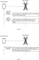
- a receiving beam for the downlink reference signal is determined.
- the receiving beam is determined as the transmitting beam for transmitting the uplink reference signal.
- S140 in the embodiment shown in conjunction with FIG. 1 further includes, but is not limited to, the following operations.
- the communication signaling is sent to the base station.
- the reference delay difference between the terminal device side and the base station side can be considered identical under the condition that the transmission path features are identical. Therefore, under the condition of sufficient signaling resources, the reference delay difference can be directly reported to the base station through signaling interaction.
- the base station obtains the uplink transmission delay of the reference path based on the reference SRS after obtaining the reference SRS, and obtains the uplink transmission delay of the LOS path based on the sum of the uplink transmission delay and the reference delay difference.
- an embodiment of the present disclosure provides a method for measuring transmission delay, which is applied to a base station.
- the method includes but is not limited to operations S710, S720 and S730.
- a downlink reference signal is sent to a terminal device, to cause the terminal device to determine the LOS path and the reference path from the transmission paths of the downlink reference signal.
- an uplink reference signal sent by the terminal device is acquired, and an uplink transmission delay of the reference path is acquired based on the uplink reference signal.
- a reference delay difference reported by the terminal device is acquired, and an uplink transmission delay of the LOS path is acquired based on the uplink transmission delay of the reference path and the reference delay difference, where the reference delay difference is the difference between a downlink transmission delay of the LOS path and a downlink transmission delay of the reference path.
- the downlink reference signal sent by the base station to the terminal device may be triggered by a request for positioning that may be initiated by the base station, the terminal device or the positioning server, which is not limited in this embodiment.
- the base station and the terminal device can agree on the reporting scheme of the reference delay difference through the configuration information, thus the uplink transmission delay of the LOS path can be obtained in conjunction with the uplink transmission delay of the reference path.
- those having ordinary skills in the art can also conceive making relevant configuration at the base station, and determining the signal strength after receiving the uplink reference signal, such as setting a certain power threshold or trying to obtain the uplink transmission delay of the LOS path. If the signal strength of the uplink reference signal is sufficient to directly obtain the uplink transmission delay of the LOS path, the uplink transmission delay of the LOS path can be directly obtained according to the practical requirement.
- the technical scheme set forth in an embodiment of the present disclosure can still be adopted, and the uplink transmission delay of the LOS path can be calculated through the uplink transmission delay of the reference path in conjunction with the reference delay difference, which is not limited in this embodiment.
- the uplink reference signal is the Sounding Reference Symbol (SRS).
- SRS Sounding Reference Symbol
- a reference SRS sent by the terminal device is acquired.
- a reference path is determined from the transmission paths of the reference SRS.
- the method for determining the reference path after the base station receives the SRS can refer to the description of the embodiment shown in FIG. 3 , and will not be repeated here for the sake of simplicity.
- S730 in the embodiment shown in conjunction with FIG. 7 further includes, but is not limited to, the following operations.
- a modulated SRS and a reference SRS sent by the terminal device are acquired, where the modulated SRS is obtained from modulating a new reference SRS generated by the terminal device based on the reference delay difference.
- a reference delay difference is acquired based on the modulated SRS and the reference SRS.
- the method of obtaining the reference delay difference based on the modulated SRS and the reference SRS can refer to the description of the embodiment shown in FIG. 4 , and will not be repeated here for the sake of simplicity.
- the method further includes but is not limited to the following operations.
- a transmitting beam for transmitting a downlink reference signal is determined.
- the transmitting beam is determined as the receiving beam for receiving the uplink reference signal.
- S730 in the embodiment shown in conjunction with FIG. 7 further includes, but is not limited to, the following operations.
- a communication signaling sent by the terminal device is acquired, where the communication signaling carries the reference delay difference.
- SRS is utilized as the uplink reference signal; the reference path is taken as the transmission path with the strongest signal power. Also, the transmitting beam and the receiving beam of the uplink reference signal and the downlink reference signal can be considered to be identical to ensure that the relative relationship between the transmission paths is identical.
- Example embodiment 1 reporting the reference delay difference by modulated SRS.
- the method for measuing transmission delay includes but is not limited to the following operations
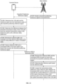
- a base station sends a downlink positioning reference signal to a terminal device.
- the terminal device determines the LOS path and the reference path from the transmission paths of the downlink positioning reference signal.
- the terminal device determines the difference between the downlink transmission delay of the LOS path and the downlink transmission delay of the reference path as the reference delay difference.
- the terminal device At S1240, the terminal device generates two reference SRSs, and modulates one of the reference SRSs based on the reference delay difference to obtain a modulated SRS.
- the terminal device sends a reference SRS and a modulated SRS to the base station by a beam that receives the downlink positioning reference signal.
- the base station receives the reference SRS and the modulated SRS through the beam that transmits the downlink positioning reference signal.
- the base station determines the reference path based on the reference SRS.
- the base station obtains the transmission delay difference of the reference path between the modulated SRS and the reference SRS, and calculates the symbol difference in conjunction of the uplink transmission delay of the reference path in the reference SRS to obtain the uplink transmission delay of the LOS path.
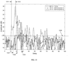
- FIG. 13 depicts a spectrum diagram obtained based on the embodiment shown in FIG. 12 .
- the signal at the lower side of the noise floor reference line 1330 is the noise floor, i.e., the waveform formed by noise and interference in the transmission path.
- the transmission (Tx) power of the base station (BS) is sufficient, it can be determined in the spectrum received (Rx) by the terminal device (TD) that the first detected signal is the downlink positioning reference signal transmitted through the LOS path, i.e., the first peak 1311 shown in FIG. 13 .
- the signal transmission path corresponding to the first peak 1311 can be considered as the LOS path, and the point with the largest signal power is the second peak 1312, so the signal transmission path corresponding to the second peak 1312 is the reference path.
- symbol 1 shown in the FIG. 13 is the reference SRS
- symbol 2 is the modulated SRS
- the first peak 1311 is generated before the second peak 1312. Since both the transmitting end and the receiving end employ an identical beam, it can be considered that the transmission signal sent through the LOS path received at the base station side should also be prior to the transmission signal sent through the reference path.
- the point with the strongest signal power is the fourth peak 1322
- the third peak 1321 to the left of the fourth peak 1322 is at the lower side of the noise floor reference line 1330, that is, the transmission signal of the LOS path has been submerged by noise.
- the fifth peak 1323 obtained by modulated SRS and the fourth peak 1322 corresponding to the reference SRS correspond to the reference path and are easy to detect in the frequency spectrum. Therefore, the uplink transmission delay of the reference path can be obtained, and then the uplink transmission delay of the LOS path can be calculated by the above method. Thereby, the measurement of the uplink transmission delay of the LOS path can be completed by SRS over only two symbols under the condition of low power of the terminal device, and the resource overhead in the RTT measurement is reduced.
- Example embodiment 2 reporting the reference delay difference through signaling interaction.
- the method for measuring transmission delay includes but is not limited to the following operations.
- a base station sends a downlink positioning reference signal to a terminal device.
- the terminal device determines the LOS path and the reference path from the transmission paths of the downlink positioning reference signal.
- the terminal device determines the difference between the downlink transmission delay of the LOS path and the downlink transmission delay of the reference path as the reference delay difference, and sends the reference delay difference to the base station through signaling interaction.
- the terminal device generates a reference SRS and sends the reference SRS to the base station through the beam that receives the downlink positioning reference signal.
- the reference SRS is received through the beam that transmits the downlink positioning reference signal.
- the reference path is determined based on the reference SRS.
- the uplink transmission delay of the LOS path is calculated based on the reference delay difference and the uplink transmission delay of the reference path.
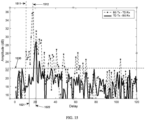
- FIG. 15 depicts a spectrum diagram obtained according to the embodiment shown in FIG. 14 .
- the signal at the lower side of the noise floor reference line 1530 is the noise floor, i.e., the waveform formed by noise and interference in the transmission path. Since the transmission power of the base station is sufficient, it can be determined in the spectrum received by the terminal device that the first detected signal is the downlink positioning reference signal transmitted through the LOS path, i.e., the first peak 1511 shown in FIG. 15 .
- the signal transmission path corresponding to the first peak 1511 can be considered as the LOS path, and the point with the largest signal power is the second peak 1512, so the signal transmission path corresponding to the second peak 1512 is the reference path.
- the first peak 1511 is generated before the second peak 1512. Since both the transmitting end and the receiving end employ identical beam, it can be considered that the transmission signal sent through the LOS path received at the base station side should also be prior to the transmission signal sent through the reference path.
- the point with the strongest signal power is the fourth peak 1522, and the third peak 1521 to the left of the fourth peak 1522 is at the lower side of the noise floor reference line 1530, that is, the transmission signal of the LOS path has been submerged by noise. Therefore, the fourth peak 1522 is easy to detect in the frequency spectrum. Therefore, the uplink transmission delay of the reference path can be obtained, and then the uplink transmission delay of the LOS path can be calculated in combination with the reference delay difference obtained through signaling interaction which reduces the resource overhead in the RTT measurement.
- An embodiment of the present disclosure provides a method for positioning, which is applied to a positioning server that is respectively in communicative connection with a base station and a terminal device.
- the method includes but is not limited to operations S1610 and S1620.
- a downlink transmission delay of a LOS path sent by a terminal device and an uplink transmission delay of the LOS path sent by a base station are acquired, where the uplink transmission delay of the LOS path is obtained from the method for measuring transmission delay according to the embodiment shown in FIG. 1 or FIG. 7 .
- the location information of the terminal device is determined based on the downlink transmission delay and uplink transmission delay of the LOS path.
- the uplink transmission delay of the LOS path can refer to the method of the embodiment shown in FIG. 1 or FIG. 8 , and will not be described here for simplicity.
- the request for positioning may be initiated by the positioning server, the terminal device, or the base station, which is not limited in this embodiment.
- the terminal device and the base station report the transmission delay of the LOS path to the positioning server respectively. Since the method of the embodiment shown in FIG. 1 or FIG. 8 is adopted to measure the transmission delay, not only can the resource overhead be reduced, but also the measurement efficiency of the uplink transmission delay of the LOS path can be effectively improved since only SRS over at most two symbols is needed, and the wait for receiving and sending multiple SRS are eliminated, thus realizing rapid positioning.
- the location information of the terminal device can be determined in any way, such as the RTT measurement method specified in the relevant standards, and this embodiment does not limit this.
- an embodiment of the present disclosure provides a terminal device, which includes a memory 1710, a processor 1720 and a computer program stored in the memory 1710 and executable by the processor 1720.
- the processor 1720 and the memory 1710 may be connected by a bus or other means.
- Non-transitory software programs and instructions of the method described in the above embodiments are stored in a memory 1710 which, when executed by a processor 1720, cause the processor 1720 to carry out operations of the method described above, for example, the above-described operations S110 to S140 described in conjunction with FIG. 1 , S210 to S220 described in conjunction with FIG. 2 , S310 to S320 described in conjunction with FIG. 3 , S410 to S420 described in conjunction with FIG. 4 , S510-S520 described in conjunction with FIG. 5 , or S610 to S620 described in conjunction with FIG. 6 .
- an embodiment of the present disclosure provides a base station 1800, which includes a memory 1810, a processor 1820 and a computer program stored in the memory 1810 and executable by the processor 1820.
- the processor 1820 and the memory 1810 may be connected by a bus or other means.
- Non-transitory software programs and instructions for the method for measuring transmission delay of any one of the above embodiments are stored in a memory 1810 which, when executed by a processor 1820, cause the processor 1820 to carry out the method described in any one of the above embodiments, for example, the operations S710 to S730 described in conjunction with FIG. 7 , S810 to S820 described in conjunction with FIG. 8 , S910 to S920 described in conjunction with FIG. 9 , S1010 to S1020 described in conjunction with FIG. 10 , or S1110 described in conjunction with FIG. 11 .
- An embodiment of the present disclosure provides a computer-readable storage medium, which stores computer-executable instructions which, when executed by processor or a controller, for example, by a processor in the embodiment concerning the terminal device, causes the processor to carry out the operations of the method for measuring transmission delay applied to the terminal device described above, for example, the above-described operations S110 to S140 described in conjunction with FIG. 1 , S210 to S220 described in conjunction with FIG. 2 , S310 to S320 described in conjunction with FIG. 3 , S410 to S420 described in conjunction with FIG.4 , S510 to S520 described in conjunction with FIG. 5 , S610 to S620 described in conjunction with FIG. 6 .
- the computer-executable instructions which, when executed by processor or a controller, for example, by a processor in the embodiment concerning the base station, causes the processor to carry out the operations of the method for measuring transmission delay applied to the base station described above, for example, S710 to S730 described in conjunction with FIG.7 , S810 to S820 described in conjunction with FIG. 8 , S910 to S920 described in conjunction with FIG. 9 , S1010 to S1020 described in conjunction with FIG. 10 , or S1110 described in conjunction with FIG. 11 .
- all or some of the steps and systems disclosed above can be implemented as software, firmware, hardware and their appropriate combinations.
- Some or all physical components can be implemented as software executed by a processor, such as a central processing unit, a digital signal processor or a microprocessor, or as hardware, or as an integrated circuit, such as an application specific integrated circuit.
- a processor such as a central processing unit, a digital signal processor or a microprocessor, or as hardware, or as an integrated circuit, such as an application specific integrated circuit.
- Such software can be distributed on computer-readable media, which can include computer storage media (or non-transitory media) and communication media (or transitory media).
- computer storage medium includes volatile and nonvolatile, removable and non-removable medium implemented in any method or technology for storing information such as computer readable instructions, data structures, program modules or other data.
- Computer storage medium includes, but is not limited to, RAM, ROM, EEPROM, flash memory or other memory technologies, CD-ROM, digital versatile disks (DVD) or other optical disk storage, magnetic boxes, tapes, magnetic disk storage or other magnetic storage devices, or any other medium that can be used to store desired information and accessible by a computer.
- communication media usually contains computer-readable instructions, data structures, program modules or other data in modulated data signals such as carrier waves or other transmission mechanisms, and can include any information delivery media.
- the method includes, acquiring a downlink reference signal sent by a base station, and determining a line of sight (LOS) path and a reference path from a plurality of transmission paths of the downlink reference signal; acquiring a reference delay difference that is a difference between a downlink transmission delay of the LOS path and the downlink transmission delay of the reference path; sending an uplink reference signal to the base station, to cause the base station to obtain an uplink transmission delay of the reference path based on the uplink reference signal; and reporting the reference delay difference to the base station, to cause the base station to obtain the uplink transmission delay of the LOS path based on the uplink transmission delay of the reference path and the reference delay difference.
- LOS line of sight
- the base station is enabled to obtain the uplink transmission delay of the reference path through one uplink reference signal, under the condition of the limited uplink power of the terminal device, and the uplink transmission delay of the LOS path is calculated through the uplink transmission delay of the reference path in conjunction with the reference delay difference, thus effectively reducing the resource overhead for measuring the uplink transmission delay of the LOS path.
Landscapes
- Engineering & Computer Science (AREA)
- Computer Networks & Wireless Communication (AREA)
- Signal Processing (AREA)
- Physics & Mathematics (AREA)
- Electromagnetism (AREA)
- Radar, Positioning & Navigation (AREA)
- Remote Sensing (AREA)
- Quality & Reliability (AREA)
- Environmental & Geological Engineering (AREA)
- General Physics & Mathematics (AREA)
- Mobile Radio Communication Systems (AREA)
- Position Fixing By Use Of Radio Waves (AREA)
Applications Claiming Priority (2)
| Application Number | Priority Date | Filing Date | Title |
|---|---|---|---|
| CN202110607662.5A CN115426672A (zh) | 2021-06-01 | 2021-06-01 | 传输时延测量方法、定位方法、终端、基站、存储介质 |
| PCT/CN2022/093299 WO2022252979A1 (fr) | 2021-06-01 | 2022-05-17 | Procédé de mesure de retard de transmission, procédé de positionnement, terminal, station de base et support de stockage |
Publications (2)
| Publication Number | Publication Date |
|---|---|
| EP4354986A1 true EP4354986A1 (fr) | 2024-04-17 |
| EP4354986A4 EP4354986A4 (fr) | 2024-11-06 |
Family
ID=84230429
Family Applications (1)
| Application Number | Title | Priority Date | Filing Date |
|---|---|---|---|
| EP22815026.4A Pending EP4354986A4 (fr) | 2021-06-01 | 2022-05-17 | Procédé de mesure de retard de transmission, procédé de positionnement, terminal, station de base et support de stockage |
Country Status (5)
| Country | Link |
|---|---|
| US (1) | US20240373272A1 (fr) |
| EP (1) | EP4354986A4 (fr) |
| JP (1) | JP7637801B2 (fr) |
| CN (1) | CN115426672A (fr) |
| WO (1) | WO2022252979A1 (fr) |
Families Citing this family (2)
| Publication number | Priority date | Publication date | Assignee | Title |
|---|---|---|---|---|
| KR20220169821A (ko) * | 2021-06-21 | 2022-12-28 | 삼성전자주식회사 | 다중 대역 채널 추정을 통한 가시 경로 채널을 활용하는 방법 및 장치 |
| CN120021319A (zh) * | 2023-11-20 | 2025-05-20 | 华为技术有限公司 | 信号传输方法和通信装置 |
Family Cites Families (18)
| Publication number | Priority date | Publication date | Assignee | Title |
|---|---|---|---|---|
| US20080130794A1 (en) | 2006-12-04 | 2008-06-05 | Chia-Chin Chong | Method for optimum threshold selection of time-of-arrival estimators |
| CN101472334A (zh) * | 2007-12-28 | 2009-07-01 | 三星电子株式会社 | 无线蜂窝网中消除nlos的方法和装置 |
| CN101790188B (zh) * | 2009-01-24 | 2014-10-08 | 华为技术有限公司 | 一种调整时间偏置的方法及用户终端 |
| CN102387526B (zh) * | 2010-08-30 | 2016-02-10 | 中兴通讯股份有限公司 | 一种提高无线蜂窝系统定位精度的方法及装置 |
| EP2584849B1 (fr) | 2011-10-17 | 2019-02-27 | Commissariat à l'Énergie Atomique et aux Énergies Alternatives | Procédé de positionnement de noeuds pour un réseau sans fil |
| CN104662436B (zh) * | 2012-10-08 | 2018-03-16 | 华为技术有限公司 | 定位方法和装置 |
| US11122628B2 (en) | 2017-01-06 | 2021-09-14 | Ntt Docomo, Inc. | User equipment apparatus, base station, and random access method |
| CN110012536B (zh) * | 2018-01-05 | 2021-10-01 | 华为技术有限公司 | 用于终端设备的定位方法、装置及系统 |
| US20190271775A1 (en) | 2018-03-01 | 2019-09-05 | Qualcomm Incorporated | Motion detection using the magnitude of channel impulse response |
| JP7289189B2 (ja) * | 2018-06-28 | 2023-06-09 | シャープ株式会社 | 端末装置、ロケーションサーバー及び方法 |
| CN110944382B (zh) * | 2018-09-25 | 2021-03-09 | 北京紫光展锐通信技术有限公司 | 用户终端的定位方法、基站及计算机可读存储介质 |
| CN112640568B (zh) * | 2018-09-26 | 2022-06-28 | 富士通株式会社 | 信号发送方法、信号接收方法及装置 |
| JP7185030B2 (ja) | 2018-10-05 | 2022-12-06 | テレフオンアクチーボラゲット エルエム エリクソン(パブル) | ビームベースのポジショニング測定および測定報告 |
| US11490354B2 (en) * | 2019-01-11 | 2022-11-01 | Qualcomm Incorporated | Round-trip-time (RTT)-based positioning with listening nodes |
| US11329780B2 (en) * | 2019-01-16 | 2022-05-10 | Qualcomm Incorporated | Physical layer non-line-of-sight (LOS) path discrimination using multiple frequency carriers |
| CN111257901A (zh) * | 2020-02-28 | 2020-06-09 | 西南电子技术研究所(中国电子科技集团公司第十研究所) | 多径传播条件下散射体位置已知的定位方法 |
| CN112034419B (zh) * | 2020-09-08 | 2024-02-06 | 北京邮电大学 | 一种用于5g定位的传播时延估计方法和装置 |
| US12000944B2 (en) * | 2020-10-13 | 2024-06-04 | Samsung Electronics Co., Ltd. | Positioning system with NLOS identification and multipath mitigation |
-
2021
- 2021-06-01 CN CN202110607662.5A patent/CN115426672A/zh active Pending
-
2022
- 2022-05-17 US US18/565,803 patent/US20240373272A1/en active Pending
- 2022-05-17 JP JP2023574509A patent/JP7637801B2/ja active Active
- 2022-05-17 WO PCT/CN2022/093299 patent/WO2022252979A1/fr not_active Ceased
- 2022-05-17 EP EP22815026.4A patent/EP4354986A4/fr active Pending
Also Published As
| Publication number | Publication date |
|---|---|
| US20240373272A1 (en) | 2024-11-07 |
| WO2022252979A1 (fr) | 2022-12-08 |
| CN115426672A (zh) | 2022-12-02 |
| JP7637801B2 (ja) | 2025-02-28 |
| JP2024520139A (ja) | 2024-05-21 |
| EP4354986A4 (fr) | 2024-11-06 |
Similar Documents
| Publication | Publication Date | Title |
|---|---|---|
| US10673653B2 (en) | Preamble detection and time-of-arrival estimation for a single-tone frequency hopping random access preamble | |
| US20190239249A1 (en) | Processing of random access preamble sequences | |
| US11812416B2 (en) | Coherent detection of large physical random access control channel (PRACH) delays | |
| EP3025466B1 (fr) | Procédé et appareil d'estimation d'un rapport signal sur interférence plus bruit d'un canal à accès aléatoire d'un réseau sans fil | |
| US10201018B2 (en) | Transmission and reception of a random access preamble signal | |
| US10897744B2 (en) | Uplink synchronization timing deviation determination method and device | |
| EP4354986A1 (fr) | Procédé de mesure de retard de transmission, procédé de positionnement, terminal, station de base et support de stockage | |
| US12309733B2 (en) | Signal sending and processing method and apparatus | |
| RU2015156301A (ru) | Устройство и способ управления передачей данных, система радиопередачи данных и устройство терминала | |
| WO2016123790A1 (fr) | Procédé et appareil pour une détection de préambule d'accès aléatoire | |
| US20210345130A1 (en) | Positioning reference signal transmission method and apparatus, device, and storage medium | |
| TWI435577B (zh) | 在通訊系統中傳送測距前置碼至基地台的使用者終端及方法 | |
| CN112788750A (zh) | Srs传输方法、装置、网络设备、终端和存储介质 | |
| CN101399607B (zh) | 一种无线通信系统中的测距方法和装置 | |
| KR102130585B1 (ko) | 협대역 무선 통신 시스템의 동기 획득 장치 및 그 방법 | |
| WO2025056154A1 (fr) | Procédés, dispositif de communication et émetteur satellite pour synchronisation de cellules dans un système de communication mobile par satellite en orbite non géostationnaire | |
| US12341640B2 (en) | Methods for reference signalling, transmitter nodes and receiver nodes | |
| EP3886387B1 (fr) | Dispositif de transmission sans fil, dispositif de réception sans fil et procédé de communication sans fil | |
| US20260046810A1 (en) | Carrier phase positioning technique | |
| CN119520200B (zh) | 一种面向航空通信的随机接入前导检测方法 | |
| KR20190106674A (ko) | 무선 분산 통신 시스템에서 톤 채널 이용 방법 및 장치 |
Legal Events
| Date | Code | Title | Description |
|---|---|---|---|
| STAA | Information on the status of an ep patent application or granted ep patent |
Free format text: STATUS: THE INTERNATIONAL PUBLICATION HAS BEEN MADE |
|
| PUAI | Public reference made under article 153(3) epc to a published international application that has entered the european phase |
Free format text: ORIGINAL CODE: 0009012 |
|
| STAA | Information on the status of an ep patent application or granted ep patent |
Free format text: STATUS: REQUEST FOR EXAMINATION WAS MADE |
|
| 17P | Request for examination filed |
Effective date: 20231219 |
|
| AK | Designated contracting states |
Kind code of ref document: A1 Designated state(s): AL AT BE BG CH CY CZ DE DK EE ES FI FR GB GR HR HU IE IS IT LI LT LU LV MC MK MT NL NO PL PT RO RS SE SI SK SM TR |
|
| DAV | Request for validation of the european patent (deleted) | ||
| DAX | Request for extension of the european patent (deleted) | ||
| A4 | Supplementary search report drawn up and despatched |
Effective date: 20241009 |
|
| RIC1 | Information provided on ipc code assigned before grant |
Ipc: H04W 24/08 20090101ALI20241002BHEP Ipc: H04B 17/24 20150101ALI20241002BHEP Ipc: H04B 17/364 20150101ALI20241002BHEP Ipc: H04B 17/10 20150101ALI20241002BHEP Ipc: H04L 5/00 20060101ALI20241002BHEP Ipc: H04W 64/00 20090101AFI20241002BHEP |
|
| STAA | Information on the status of an ep patent application or granted ep patent |
Free format text: STATUS: EXAMINATION IS IN PROGRESS |
|
| 17Q | First examination report despatched |
Effective date: 20251204 |