EP4355249B1 - Medizinischer roboter zur platzierung medizinischer instrumente unter ultraschallführung - Google Patents
Medizinischer roboter zur platzierung medizinischer instrumente unter ultraschallführung Download PDFInfo
- Publication number
- EP4355249B1 EP4355249B1 EP22741336.6A EP22741336A EP4355249B1 EP 4355249 B1 EP4355249 B1 EP 4355249B1 EP 22741336 A EP22741336 A EP 22741336A EP 4355249 B1 EP4355249 B1 EP 4355249B1
- Authority
- EP
- European Patent Office
- Prior art keywords
- patient
- image
- ultrasound
- marker
- medical
- Prior art date
- Legal status (The legal status is an assumption and is not a legal conclusion. Google has not performed a legal analysis and makes no representation as to the accuracy of the status listed.)
- Active
Links
Images



Classifications
-
- A—HUMAN NECESSITIES
- A61—MEDICAL OR VETERINARY SCIENCE; HYGIENE
- A61B—DIAGNOSIS; SURGERY; IDENTIFICATION
- A61B34/00—Computer-aided surgery; Manipulators or robots specially adapted for use in surgery
- A61B34/30—Surgical robots
-
- A—HUMAN NECESSITIES
- A61—MEDICAL OR VETERINARY SCIENCE; HYGIENE
- A61B—DIAGNOSIS; SURGERY; IDENTIFICATION
- A61B34/00—Computer-aided surgery; Manipulators or robots specially adapted for use in surgery
- A61B34/20—Surgical navigation systems; Devices for tracking or guiding surgical instruments, e.g. for frameless stereotaxis
-
- A—HUMAN NECESSITIES
- A61—MEDICAL OR VETERINARY SCIENCE; HYGIENE
- A61B—DIAGNOSIS; SURGERY; IDENTIFICATION
- A61B34/00—Computer-aided surgery; Manipulators or robots specially adapted for use in surgery
- A61B34/25—User interfaces for surgical systems
-
- A—HUMAN NECESSITIES
- A61—MEDICAL OR VETERINARY SCIENCE; HYGIENE
- A61B—DIAGNOSIS; SURGERY; IDENTIFICATION
- A61B34/00—Computer-aided surgery; Manipulators or robots specially adapted for use in surgery
- A61B34/30—Surgical robots
- A61B34/32—Surgical robots operating autonomously
-
- A—HUMAN NECESSITIES
- A61—MEDICAL OR VETERINARY SCIENCE; HYGIENE
- A61B—DIAGNOSIS; SURGERY; IDENTIFICATION
- A61B90/00—Instruments, implements or accessories specially adapted for surgery or diagnosis and not covered by any of the groups A61B1/00 - A61B50/00, e.g. for luxation treatment or for protecting wound edges
- A61B90/10—Instruments, implements or accessories specially adapted for surgery or diagnosis and not covered by any of the groups A61B1/00 - A61B50/00, e.g. for luxation treatment or for protecting wound edges for stereotaxic surgery, e.g. frame-based stereotaxis
- A61B90/11—Instruments, implements or accessories specially adapted for surgery or diagnosis and not covered by any of the groups A61B1/00 - A61B50/00, e.g. for luxation treatment or for protecting wound edges for stereotaxic surgery, e.g. frame-based stereotaxis with guides for needles or instruments, e.g. arcuate slides or ball joints
-
- A—HUMAN NECESSITIES
- A61—MEDICAL OR VETERINARY SCIENCE; HYGIENE
- A61B—DIAGNOSIS; SURGERY; IDENTIFICATION
- A61B17/00—Surgical instruments, devices or methods
- A61B2017/00681—Aspects not otherwise provided for
- A61B2017/00694—Aspects not otherwise provided for with means correcting for movement of or for synchronisation with the body
- A61B2017/00699—Aspects not otherwise provided for with means correcting for movement of or for synchronisation with the body correcting for movement caused by respiration, e.g. by triggering
-
- A—HUMAN NECESSITIES
- A61—MEDICAL OR VETERINARY SCIENCE; HYGIENE
- A61B—DIAGNOSIS; SURGERY; IDENTIFICATION
- A61B34/00—Computer-aided surgery; Manipulators or robots specially adapted for use in surgery
- A61B34/10—Computer-aided planning, simulation or modelling of surgical operations
- A61B2034/107—Visualisation of planned trajectories or target regions
-
- A—HUMAN NECESSITIES
- A61—MEDICAL OR VETERINARY SCIENCE; HYGIENE
- A61B—DIAGNOSIS; SURGERY; IDENTIFICATION
- A61B34/00—Computer-aided surgery; Manipulators or robots specially adapted for use in surgery
- A61B34/20—Surgical navigation systems; Devices for tracking or guiding surgical instruments, e.g. for frameless stereotaxis
- A61B2034/2046—Tracking techniques
- A61B2034/2055—Optical tracking systems
-
- A—HUMAN NECESSITIES
- A61—MEDICAL OR VETERINARY SCIENCE; HYGIENE
- A61B—DIAGNOSIS; SURGERY; IDENTIFICATION
- A61B34/00—Computer-aided surgery; Manipulators or robots specially adapted for use in surgery
- A61B34/20—Surgical navigation systems; Devices for tracking or guiding surgical instruments, e.g. for frameless stereotaxis
- A61B2034/2046—Tracking techniques
- A61B2034/2059—Mechanical position encoders
-
- A—HUMAN NECESSITIES
- A61—MEDICAL OR VETERINARY SCIENCE; HYGIENE
- A61B—DIAGNOSIS; SURGERY; IDENTIFICATION
- A61B34/00—Computer-aided surgery; Manipulators or robots specially adapted for use in surgery
- A61B34/20—Surgical navigation systems; Devices for tracking or guiding surgical instruments, e.g. for frameless stereotaxis
- A61B2034/2046—Tracking techniques
- A61B2034/2063—Acoustic tracking systems, e.g. using ultrasound
-
- A—HUMAN NECESSITIES
- A61—MEDICAL OR VETERINARY SCIENCE; HYGIENE
- A61B—DIAGNOSIS; SURGERY; IDENTIFICATION
- A61B90/00—Instruments, implements or accessories specially adapted for surgery or diagnosis and not covered by any of the groups A61B1/00 - A61B50/00, e.g. for luxation treatment or for protecting wound edges
- A61B90/06—Measuring instruments not otherwise provided for
- A61B2090/064—Measuring instruments not otherwise provided for for measuring force, pressure or mechanical tension
-
- A—HUMAN NECESSITIES
- A61—MEDICAL OR VETERINARY SCIENCE; HYGIENE
- A61B—DIAGNOSIS; SURGERY; IDENTIFICATION
- A61B90/00—Instruments, implements or accessories specially adapted for surgery or diagnosis and not covered by any of the groups A61B1/00 - A61B50/00, e.g. for luxation treatment or for protecting wound edges
- A61B90/36—Image-producing devices or illumination devices not otherwise provided for
- A61B2090/364—Correlation of different images or relation of image positions in respect to the body
-
- A—HUMAN NECESSITIES
- A61—MEDICAL OR VETERINARY SCIENCE; HYGIENE
- A61B—DIAGNOSIS; SURGERY; IDENTIFICATION
- A61B90/00—Instruments, implements or accessories specially adapted for surgery or diagnosis and not covered by any of the groups A61B1/00 - A61B50/00, e.g. for luxation treatment or for protecting wound edges
- A61B90/36—Image-producing devices or illumination devices not otherwise provided for
- A61B90/37—Surgical systems with images on a monitor during operation
- A61B2090/378—Surgical systems with images on a monitor during operation using ultrasound
-
- A—HUMAN NECESSITIES
- A61—MEDICAL OR VETERINARY SCIENCE; HYGIENE
- A61B—DIAGNOSIS; SURGERY; IDENTIFICATION
- A61B90/00—Instruments, implements or accessories specially adapted for surgery or diagnosis and not covered by any of the groups A61B1/00 - A61B50/00, e.g. for luxation treatment or for protecting wound edges
- A61B90/39—Markers, e.g. radio-opaque or breast lesions markers
- A61B2090/3925—Markers, e.g. radio-opaque or breast lesions markers ultrasonic
-
- A—HUMAN NECESSITIES
- A61—MEDICAL OR VETERINARY SCIENCE; HYGIENE
- A61B—DIAGNOSIS; SURGERY; IDENTIFICATION
- A61B90/00—Instruments, implements or accessories specially adapted for surgery or diagnosis and not covered by any of the groups A61B1/00 - A61B50/00, e.g. for luxation treatment or for protecting wound edges
- A61B90/39—Markers, e.g. radio-opaque or breast lesions markers
- A61B2090/3966—Radiopaque markers visible in an X-ray image
Definitions
- the present application belongs to the field of robotic devices for assisting a practitioner during a minimally invasive medical procedure comprising the insertion of one or more medical instruments into an anatomy of interest of a patient.
- the invention relates to a medical robot configured to follow the movement of a target point in a lesion within an anatomy of interest of a patient and to adjust in real time the position of an articulated arm of the robot to optimally guide a medical instrument towards the target point.
- the movement of the target point may in particular be generated by the patient's breathing, or by the insertion of the medical instrument.
- a practitioner To prepare a minimally invasive procedure to reach a target anatomical area in a patient's anatomy of interest with a medical instrument, a practitioner generally plans the procedure based on a preoperative medical image (a few days or weeks before the procedure) or pre-interventional (just before the procedure when the patient is installed on the operating table).
- the minimally invasive medical procedure may in particular aim to perform a biopsy or ablation of a tumor in an organ, to perform a vertebroplasty, a cementoplasty or to stimulate a particular anatomical area.
- the anatomy of interest may correspond, for example, to a lung, a kidney, the liver, the brain, the tibia, the knee, a vertebra, etc.
- the medical instrument may be a needle, a probe, a catheter, etc.
- the practitioner defines a target point in a region of the anatomy of interest to be treated.
- the practitioner also defines an entry point for the medical instrument on the patient's skin. These two points then define a trajectory that the medical instrument must follow to perform the medical intervention.
- movements related to the patient's breathing and/or local deformations of the organ due to the insertion of the medical instrument cause a displacement of the target point during the intervention.
- Preoperative or pre-interventional planning medical images do not allow predict this displacement of the target point during the intervention.
- the position of the target point i.e.
- the position of the region to be treated in the anatomy of interest is usually different when acquiring the planning medical image and during the intervention. Therefore, when the insertion of the medical instrument is planned from the planning medical image, there is a risk that the target point will not be reached accurately by the medical instrument.
- the patent application US2008/287794A1 discloses a method for implementing an imaging and navigation system to perform a medical procedure such as cardiac ablation.
- the method includes using an ultrasound imaging device to provide a three-dimensional image of the patient in real time, identifying a target site on the three-dimensional image of the patient in real time, directing a medical instrument to the target site using a tracking system, and performing the medical procedure at the target site.
- the patent application US2014/316247A1 discloses a method and apparatus for tracking a change in a region of interest in a subject as a function of respiration.
- a "respiration signal” is captured using ultrasound images. This is a time-dependent representation of the movement of the region of interest.
- the patent application US2018/092628A1 describes an ultrasound diagnostic device. Data from an ultrasound image acquired by an ultrasound probe are associated with the position of the probe. Image alignment between the ultrasound image and a medical image can be performed.
- a medical robot for assisting a practitioner during a medical intervention to treat a lesion in an anatomy of interest of a patient.
- the medical robot comprises a robotic arm comprising at a distal end a tool guide intended to guide a medical instrument.
- the robot medical robot also comprises a control unit configured to control the robotic arm.
- the medical robot is configured to cooperate with a navigation system and with an ultrasound probe intended to be positioned by the practitioner at the level of the anatomy of interest of the patient.
- the control unit is configured to be able to determine at any time, from information communicated by the navigation system, the position of a robot marker intended to be fixed on the medical robot, the position of a patient marker intended to be positioned on the patient near the anatomy of interest, and the position of a probe marker intended to be fixed on the ultrasound probe.
- the control unit is configured to receive a plurality of ultrasound images acquired by the ultrasound probe during at least one respiratory cycle of the patient and to generate, from said ultrasound images, a model for estimating the position of a target point at the lesion and the position of an entry point at the patient's skin, as a function of the position of the patient marker, regardless of the moment considered in a respiratory cycle of the patient.
- control unit is configured to control the robotic arm in real time as a function of the position of the patient marker to guide the medical instrument along a trajectory defined by the position of the target point and the position of the entry point associated with the position of the patient marker in the model.
- position should be understood in the broad sense as describing both the position and the orientation of an object in a three-dimensional frame of reference (the term “pose” is sometimes used in the English literature).
- positions of the markers patient marker, robot marker and probe marker
- position of the target point and the position of the entry point can be defined in a frame of reference of the robot or in a frame of reference of the navigation system.
- the frame of reference of the robot can be defined relative to the frame of reference of the navigation system because the position of the robot marker is known both in the frame of reference of the navigation system and in the frame of reference of the robot (each articulation of the robotic arm comprises for example an encoder making it possible to know the position of each articulated element of the robotic arm in the frame of reference of the robot, and the position of the robot marker on the robot is known a priori by the control unit).
- the modeling phase takes place at the beginning of the intervention, before approaching the robotic arm to the anatomy of interest and before inserting the medical instrument into the patient's body.
- the modeling phase allows modeling the movement of the target point and the movement of the entry point relative to the patient marker during a respiratory cycle.
- the positions of the target point and the The entry point positions are correlated with the patient marker positions, so it is possible to define the target point position and the entry point position based on the patient marker position.
- the resulting model therefore makes it possible to define, at any time during the respiratory cycle, the target point position and the entry point position that correspond to the trajectory that the medical instrument must follow to accurately reach the target point.
- the position of the target point and the position of the entry point are modeled as a function of the position of the patient marker, it becomes possible, by following in real time the position of the patient marker using the navigation system, to define in real time the position that the robotic arm must take so that the medical instrument is guided according to the trajectory defined by the position of the target point and the position of the entry point associated with the position of the patient marker.
- This real-time tracking can in particular take place before the insertion of the medical instrument.
- the robotic arm is moved in real time so that the position of the robotic arm is constantly adjusted to guide the medical instrument along the desired trajectory.
- the invention further makes it possible to minimize lateral readjustments of the trajectory after insertion of the medical instrument (such lateral readjustments of the trajectory are generally traumatic for the organ crossed by the medical instrument).
- the medical instrument can thus be inserted into the region to be treated with very high precision, regardless of the moment of insertion of the medical instrument during the respiratory cycle.
- the insertion of the medical instrument is generally implemented by the practitioner, the medical robot being intended to guide the insertion of the medical instrument by the practitioner. However, nothing would prevent the insertion of the medical instrument from being automated and controlled by the control unit.
- the modeling of the target point position and the entry point position during a respiratory cycle is performed from ultrasound images, the patient and the practitioner are not exposed to ionizing radiation during the procedure.
- the invention may further comprise one or more of the following features, taken alone or in any technically possible combination.
- control unit is configured to model, from the information thus obtained for the plurality of ultrasound images, the position of the target point and the position of the entry point, as a function of the position of the patient marker, whatever the instant considered in a respiratory cycle of the patient.
- control unit upon insertion of the medical instrument, is configured to regularly receive new ultrasound images acquired by the ultrasound probe.
- the control unit is further configured to update the model from said new ultrasound images.
- the position of the entry point at the patient's skin is fixed and becomes a rotation pivot for the movements of the robot arm.
- Such arrangements make it possible to take into account a possible movement of the target point resulting from the insertion of the medical instrument.
- the target point can indeed move in the direction of the trajectory followed by the medical instrument during its insertion (this is in particular the case when the target point to be reached is in a lesion, for example a tumor, within a soft organ).
- Real-time determination of the position of the target point using ultrasound images makes it possible to update in real time the trajectory that the medical instrument must follow as well as the position of the robotic arm to guide the medical instrument along this trajectory.
- control unit is further configured to determine, for each new ultrasound image received, the position of the medical instrument, and to adjust the real-time control of the robotic arm based on the position of the medical instrument.
- control unit is configured to obtain the analysis image by merging the ultrasound image with a preoperative or pre-interventional reference image on which the lesion is visible.
- the lesion when the lesion is not visible on an ultrasound image (isoechogenic lesion), it is not possible to determine the position of the target point directly on the ultrasound image. It is then necessary to re-register the ultrasound image with a reference image of a different modality on which the lesion is visible.
- This may include a preoperative or pre-interventional image of computed tomography, positron emission tomography or magnetic resonance imaging.
- the fusion of the ultrasound image with the reference image then gives an analysis image on which the lesion is visible.
- the registration can be global (registration on the entire anatomy of interest) or local (optimized registration on a particular area of the anatomy of interest).
- the registration can be carried out rigidly (by translation and/or rotation) or non-rigidly (with deformation). Registration can notably be implemented by a machine learning algorithm based on the recognition of particular anatomical structures on the images to be merged.
- a radiopaque element of the patient marker is visible in the reference image
- the control unit is configured to merge the ultrasound image with the reference image by registration based on the position of the patient marker relative to the position of the probe marker at the time the ultrasound image was acquired by the ultrasound probe.
- the reference image is a computed tomography image, a positron emission tomography image, or a magnetic resonance imaging image.
- the ultrasound images received from the ultrasound probe are B-mode ultrasound images.
- control unit is configured to receive and process ultrasound images acquired by the ultrasound probe at a rate of at least fifteen images per second.
- the medical robot further comprises a user interface comprising a display screen allowing the practitioner to view the analysis images.
- the user interface comprises input means allowing the practitioner to identify on an analysis image displayed on the display screen a target point and/or an entry point and/or an anatomical zone which must not be crossed by the medical instrument.
- the tracking of the target point can in particular be implemented by a motion tracking method in several successive ultrasound images, by a deformation analysis of the "speckle” or by an artificial intelligence algorithm (the "speckle” represents the set of small rapidly fluctuating spots which appear in the instantaneous texture of an image and which give it a grainy appearance).
- the “speckle” represents the set of small rapidly fluctuating spots which appear in the instantaneous texture of an image and which give it a grainy appearance.
- the user interface includes an augmented reality device for superimposing the scan images with real images of the patient's body on the display screen.
- the augmented reality device allows the lesion in motion and in three dimensions to be superimposed on the patient's body, as well as the progression of the medical instrument during its insertion.
- This type of display facilitates the spatial representation of the patient's anatomy of interest by the practitioner.
- control unit is configured to compare an ultrasound image with a reference image in which the lesion is visible, and to provide an indication to the practitioner of the direction in which to move the ultrasound probe so that an ultrasound image acquired by the ultrasound probe includes an anatomical region in which the lesion is located.
- the reference image is, for example, a preoperative or pre-interventional image of computed tomography, positron emission tomography or magnetic resonance imaging.
- the indication of the direction in which the ultrasound probe should be moved is, for example, indicated to the practitioner on the display screen of the user interface. According to other examples, the indication of the direction in which the ultrasound probe should be moved can be indicated to the practitioner by light signals or by haptic feedback (vibrations) at the ultrasound probe, or on an augmented reality display.
- a medical device comprising a medical robot according to any one of the embodiments described above, as well as a navigation system and an ultrasound probe intended to cooperate with the medical robot.
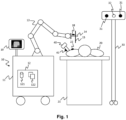
- FIG. 1 schematically represents a medical robot 10 according to the invention.
- the medical robot 10 is used to assist a practitioner during a medical intervention on an anatomy of interest of a patient 20 positioned on an intervention table 21.
- the medical robot 10 comprises a base 11.
- the base 11 of the medical robot 10 is equipped with motorized wheels, which allows the medical robot 10 to move in different directions by translational and/or rotational movements.
- the medical robot 10 further comprises an articulated robotic arm 13, one end of which is connected to the base 11. At the other end of the robotic arm 13 is fixed a tool guide 14 intended to guide a medical instrument 15, such as for example a needle, a probe, a catheter, an electrode, etc.
- a medical instrument 15 such as for example a needle, a probe, a catheter, an electrode, etc.
- the medical robot 10 can then be used to help a practitioner position, maintain, or guide the medical instrument 15 during the medical procedure.
- the medical robot 10 then plays the role of a third hand for the practitioner.
- the medical robot 10 comprises a control unit 12 configured to control the movement of the robotic arm 13.
- the control unit 12 comprises, for example, one or more processors 122 and a memory 121 (magnetic hard disk, electronic memory, optical disk, etc.) in which a computer program product is stored, in the form of a set of program code instructions to be executed to implement the different steps of a method for positioning the robotic arm 13.
- the memory 121 also makes it possible to record the images and other information (in particular the navigation information) used to implement this method.
- the medical robot 10 may also comprise a user interface 19 comprising a display screen allowing the practitioner to view ultrasound images acquired by the ultrasound probe 40 or other medical images (for example a preoperative or pre-interventional reference image of the anatomy of interest, or fusion images resulting from the registration of the ultrasound images with a reference image).
- the user interface may also comprise input means (keyboard, mouse, touch screen, etc.) allowing the practitioner to identify on an image displayed on the display screen a target point and/or an entry point and/or an anatomical area that must not be crossed by the medical instrument 15.
- the user interface may include an augmented reality device for superimposing the ultrasound images (or fusion images) with real images of the patient's body on the display screen.
- an augmented reality device for superimposing the ultrasound images (or fusion images) with real images of the patient's body on the display screen.
- Such a device facilitates the spatial representation of the anatomy of interest for the practitioner.
- the medical robot 10 is configured to cooperate with a navigation system 30 and with an ultrasound probe 40 intended to be positioned by the practitioner at the level of the anatomy of interest of the patient.
- the medical robot 10 comprises a communication module connected to the control unit 12 to exchange data with the navigation system 30 and with the ultrasound probe 40.
- the navigation system 30 and the ultrasound probe 40 also each comprise a communication module to exchange data with the control unit 12 of the medical robot 10.
- the communications established between the control unit 12, the navigation system 30 and the ultrasound probe may be wired communications or wireless communications.
- the communication modules are not shown in the figure 1 .
- the navigation system 30 is an optical navigation system.
- the navigation system 30 comprises two optical sensors 31 corresponding to two sensors of a stereoscopic camera operating in the infrared radiation range.
- the navigation system 30 further comprises a camera 32 operating in the visible light range.
- the control unit 12 is configured to be able to determine at any time, from information communicated by the navigation system 30, the position of a robot marker 18 intended to be fixed on the medical robot 10, the position of a patient marker 22 intended to be positioned on the patient 20 near the anatomy of interest, and the position of a probe marker 41 intended to be fixed on the ultrasound probe 40.
- position corresponds to the combination of the position and orientation of an object in a given frame of reference which is generally a three-dimensional coordinate system.
- pose is used in the English literature to represent this combination of the position and orientation of an object in space.
- the control unit 12 is configured to receive from the ultrasound probe 40 ultrasound images acquired by the ultrasound probe 40.
- the ultrasound images received from the ultrasound probe 40 and the information received from the navigation system 30 are temporally synchronized by the control unit 12 to be able to correlate at a given moment the position of the lesion with the position of the patient marker 22.
- the ultrasound probe 40 comprises one or more sound wave transmitter-receiver elements (piezoelectric materials, capacitive electronic transducers).
- the ultrasound probe produces ultrasound waves by indirect piezoelectric effect. Each time a wave encounters an anatomical structure, a portion of this wave returns by reflection or diffusion ("speckle") in the form of an echo. This echo is then transformed into an electric current by direct piezoelectric effect and then reconstructed into an image.
- the reconstruction of an ultrasound image depends mainly on the number, size and positions of the transmitter-receiver elements of the probe (lateral and longitudinal resolution), the duration of the emission pulses and the echo times (axial and/or depth resolution).
- the energy of the received echo is then coded in gray level. The higher the energy, the whiter the corresponding image portion (pixel).
- the images produced by the ultrasound probe 40 may be two-dimensional images or three-dimensional images.
- the ultrasound probe 40 is capable of generating images at a rate of at least fifteen frames per second.
- B-mode is particularly well suited when the anatomy of interest is the liver. It should be noted, however, that the invention could also be applied with other ultrasound modes, such as elastography.
- the robotic arm 13 comprises six rotoid joints 131 to 136 providing six degrees of freedom for positioning and/or moving the medical instrument 15 in any position in three-dimensional space.
- the joints 131 to 135 of the arm robotic arm 13 are not aligned and have an offset relative to each other, which allows a greater number of possible configurations of the robotic arm 13.
- Each joint comprises at least one encoder for knowing its angular position in real time.
- a configuration of the robotic arm 13 then corresponds to a set of parameter values taken by the joints 131 to 136 (for example the value of an angle of rotation for each joint).
- the rotoid joint 136 corresponds to a rotation about the main axis of the tool guide 14.
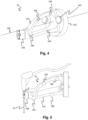
- the tool guide 14 is fixed to the robotic arm 13 by means of a flange 17.
- the tool guide comprises a main axis 145 shown in the figure 3 by a dotted line.
- the tool guide 14 is coupled to a force sensor 16 to enable the control unit 12 to determine a force exerted on the tool guide 14. This force may in particular be exerted by the practitioner when he manually moves the robotic arm 13. This force may also correspond to a force exerted on the tool guide 14 via the medical instrument 15 by the patient's body.
- the tool guide 14 comprises a body 141 with a base 142 intended to be fixed to the flange 17 using screws 143, as well as a holding system 146 comprising two parts movable relative to each other.
- the holding system 146 is intended to hold the medical instrument 15 at the end of the body 141 of the tool guide 14 opposite the base 142.
- the two movable parts of the holding system 146 can be driven by a drive system such as a gear, a cam, a screw with reverse threads and/or a linear actuator, in order to block or release the medical instrument 15.
- the linear actuator can be reversible (the holding system 146 of the tool guide 14 can then be opened manually or automatically on command from the unit of control 12) or non-reversible (the holding system 146 of the tool guide 14 can only be opened automatically on command of the control unit).
- the tool guide 14 can for example guide medical instruments of different diameters.
- such a guide can guide medical instruments whose diameter is between 11 and 21 gauges.
- the gauge is a unit of measurement commonly used to define the external diameter of a medical instrument such as a needle, a probe or a catheter (11 gauges correspond to an external diameter of 2.946 mm; 21 gauges correspond to an external diameter of 0.812 mm).
- the tool guide 14 comprises studs 144 intended to receive optical markers 181.
- the tool guide 14 comprises at least three optical markers 181 such that the position of the tool guide 14 can be determined in the three spatial dimensions of the reference frame of the navigation system 30.
- the respective positions of the optical markers 181 of the tool guide 14 relative to each other are known a priori by the navigation device 30 and/or by the control unit 12.
- the geometric shape of each optical marker 181 can also be known a priori.
- the optical markers 181 are spherical in shape.
- All the optical markers 181 present on the tool guide 14 correspond to the robot marker 18.
- optical markers 181 makes it possible to define a plane and therefore a direct orthonormal three-dimensional reference frame with a z axis normal to the plane and x and y axes in the plane so that the reference frame is direct. This thus makes it possible to determine the position and orientation of the reference frame formed from the optical markers 181 which represent the tool guide 14.
- the three axes x, y and z make it possible to define six degrees of freedom, namely a translation along each of the x, y or z axes and a rotation around each of these axes.
- the optical markers 181 may be passive or active. Passive optical markers reflect optical radiation emitted by another element, such as for example the navigation system 30. Passive optical markers may correspond for example to reflective spheres detectable by an infrared stereoscopic camera (this is what is used for example in the Polaris ® navigation systems manufactured by the company Northern Digital Inc.), or to black and white patterns visible by a stereoscopic camera (this is what is used for example in the MicronTracker ® navigation system of the company ClaroNav). Active optical markers themselves emit optical radiation, for example infrared radiation, detectable by the navigation system 30.
- the patient marker 22 is intended to be positioned on the patient 20 in the vicinity of the anatomy of interest.
- the patient marker 22 comprises four optical markers 23, such that the position of the patient marker 22 can be determined in the three spatial dimensions of the reference frame of the navigation system 30.
- the respective positions of the optical markers 23 of the patient marker 22 relative to each other are known a priori by the navigation system 30 and/or by the control unit 12.
- the geometric shape of each optical marker 23 can also be known a priori.
- the optical markers 23 are spherical in shape. The spherical shape makes it possible to optimize the reflection of the optical radiation.
- optical markers 181 of the tool guide 14 are also true for the optical markers 23 of the patient reference 22.
- optical markers 23 of the patient reference 22 it would be conceivable to use a single optical marker having a characteristic geometric shape in three dimensions instead of the four spherical optical markers 23.
- the patient marker 22 may also comprise radiopaque markers 24 which are visible on a medical image acquired by a medical imaging device (for example by computed tomography, magnetic resonance, ultrasound, tomography, positron emission tomography, etc.).
- the respective positions of the radiopaque markers 24 relative to each other are known a priori by the navigation device 30 and/or by the control unit 12.
- the geometric shape of the radiopaque markers 24 may also be known a priori.
- the patient marker 22 comprises four radiopaque markers 24.
- the radiopaque markers 24 may be, for example, ceramic balls. It should be noted, however, that a single radiopaque marker having a characteristic geometric shape in three dimensions could be used instead of the four spherical radiopaque markers 24.
- the probe marker 40 comprises three optical markers 42, such that the position of the probe marker 40 can be determined in the three spatial dimensions of the reference of the navigation system 30.
- the respective positions of the optical markers 42 of the probe marker 40 relative to each other are known a priori by the navigation system 30 and/or by the control unit 12.
- the geometric shape of each optical marker 42 can also be known a priori.
- the optical markers 42 are spherical in shape. The spherical shape makes it possible to optimize the reflection of the optical radiation.
- optical markers 181 of the tool guide 14 are also true for the optical markers 42 of the probe reference 40.
- optical markers 42 of the probe reference 40 it would be possible to use a single optical marker having a characteristic geometric shape in three dimensions instead of the three spherical optical markers 42.
- the optical sensors 31 of the navigation system 30 and the various optical markers 181, 23, 42 are designed to operate with infrared optical radiation. It is further considered that the optical markers 181, 23, 42 are passive markers.
- the optical sensors 31 are configured to emit infrared radiation. This infrared radiation is reflected by the various optical markers 181, 23, 42 towards the optical sensors 31.
- the optical sensors 31 are configured to receive this reflected infrared radiation.
- the navigation system 30 can then determine the distance between an optical marker 181, 23, 42 and an optical sensor 31 by measuring the time taken by an infrared ray to make the round trip between said optical sensor 31 and said optical marker 181, 23, 42.
- the invention is described using an optical navigation system. However, nothing would prevent the use, in a variant, of an electromagnetic navigation system instead of the optical navigation system.
- the different "markers" detectable by the navigation system would then correspond to electromagnetic sensors whose position can be determined by the navigation system in a generated electromagnetic field.
- the control unit 12 of the medical robot 10 is configured to receive from the navigation system 30 information on the current position of the robot marker 18 in the reference frame of the navigation system 30. Now, the control unit 12 of the medical robot 10 knows the current position of the robot marker 18 in the reference frame of the medical robot 10 (via the encoders of the joints 131 to 136). The control unit 12 can therefore determine the transformation to be carried out to define a position in the reference frame of the medical robot 10 from a position in the reference frame of the navigation device 30.
- the control unit 12 is also configured to receive from the navigation system 30 information on the position of the patient marker 22 and on the position of the probe marker 41 in the reference frame of the navigation system 30.
- the control unit 10 can then define the position of the patient marker 22 and the position of the probe marker 41 in the reference frame of the medical robot 10.
- This visible element may in particular be a target point to be reached at the level of the lesion to be treated or an entry point of the medical instrument at the level of the patient's skin.
- the target point and the entry point define a trajectory that the medical instrument 15 must follow.
- the control unit can automatically move the robotic arm 13 in a configuration allowing the tool guide 14 to guide the medical instrument 15 according to the defined trajectory.
- control unit 12 is configured to model, during a modeling phase that precedes the surgical procedure, the movement of the patient marker 22 during at least one respiratory cycle of the patient 20.
- the position of the target point and the position of the entry point are correlated to the position of the patient marker 22. It is thus possible to define the position of the target point and the position of the entry point as a function of the position of the patient marker.
- the modeling obtained therefore makes it possible to define, from the position of the patient marker 22, and at any time during the respiratory cycle, the position of the target point and the position of the entry point which correspond to the trajectory that the medical instrument 15 must follow to accurately reach the target point.
- the position of the target point and the position of the entry point are modeled as a function of the position of the patient marker 22, it becomes possible, by following in real time the position of the patient marker 22 using the navigation system 30, to define in real time the position that the robotic arm 13 must take so that the medical instrument 15 is guided according to the trajectory defined by the position of the target point and the position of the entry point associated with the position of the patient marker 22.
- This real-time tracking can in particular take place during a guidance phase, before the insertion of the medical instrument 15.
- the robotic arm 13 is moved in real time so that the position of the robotic arm is constantly adjusted to guide the medical instrument according to the desired trajectory.
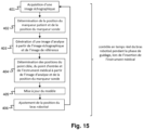
- FIG 8 schematically represents the main steps of a process implemented by the control unit 12 during a modeling phase, then during a real-time control phase of the robotic arm, before the insertion of the medical instrument 15.
- control unit 12 is configured to carry out, from the information thus obtained for the different ultrasound images, a modeling 207 of the position of the target point and the position of the entry point, depending on the position of the patient marker 22, whatever the moment considered in a patient's respiratory cycle.
- An initial determination of a target point at the lesion and an entry point at the patient's skin is, for example, initially performed on a first analysis image. Then, subsequently, a motion tracking algorithm in several successive analysis images can be implemented to determine the target point and the entry point on each new analysis image, for example using a speckle deformation analysis (set of fluctuating spots on the images due to wave diffusion) or by an artificial intelligence algorithm.
- a speckle deformation analysis set of fluctuating spots on the images due to wave diffusion
- the first determination of a target point and an entry point can be done by the practitioner using the graphical interface 19.
- the figure 9 illustrates a user interface allowing the practitioner to identify on an analysis image a target point 51 at the region to be treated 50, and/or an entry point 52 at the patient's skin, and/or a risk area to be avoided (for example bones or blood vessels), as well as treatment parameters.
- This step can be facilitated by a segmentation of certain anatomical regions (the anatomy of interest, the lesion to be treated, risk areas, etc.) by a machine learning algorithm.
- the first determination of a target point and an entry point can be implemented automatically by an artificial intelligence algorithm.
- a pre-interventional reference image i.e. an image acquired just before or at the start of the intervention
- pre-operative image i.e. an image acquired several days or weeks before the procedure
- This may include a computed tomography image, a positron emission tomography image or a magnetic resonance imaging image.
- the reference image may be a two-dimensional image or a three-dimensional image. The first determination of a target point and an entry point may then be made on the reference image instead of being made on a first ultrasound image.
- the first determination of a target point and an entry point may be made by the practitioner (e.g. using the graphical interface 19 illustrated in the figure 9 ) or automatically by an artificial intelligence algorithm.
- An ultrasound image acquired by the ultrasound probe 40 can then be recalibrated with the reference image to form an analysis image corresponding to the fusion of the reference image with the ultrasound image.
- the target point and the entry point are then visible on the analysis image.
- the first determination of a target point and an entry point may be performed on a first analysis image instead of being performed on the reference image.
- FIG 10 schematically illustrates the use of a preoperative or pre-interventional reference image (part a) of the figure 10 ) to recalibrate an ultrasound image (part b) of the figure 10 ) in order to form an analysis image (part c) of the figure 10 ) resulting from the registration and fusion of the reference image with the ultrasound image.
- the lesion to be treated 50 and the target point 51 are visible on the reference image.
- the reference image is acquired by computed tomography.
- the lesion to be treated 50 is, however, almost not visible on the ultrasound image.
- the lesion to be treated 50 and the target point 51 become visible on the analysis image resulting from the registration of the reference image with the ultrasound image.
- the registration is for example implemented by the control unit 12 using a machine learning algorithm trained to globally (registration on the entire anatomy) or locally (optimized on an area of interest), in a rigid manner (translation and rotation) or non-rigid manner (deformation) a CT image of an anatomy of interest with an ultrasound image.
- the image resulting from this registration is called an analysis image or fusion image.
- a hard registration may also be based on the position of the patient marker 22 relative to the position of the probe marker 41 at the time at which The ultrasound image was acquired by the ultrasound probe 40.
- FIG 11 schematically represents the main steps implemented during a planning phase based on a preoperative or pre-interventional reference image, then during the modeling phase, in the case where the lesion is not visible on the ultrasound images.
- the planning phase includes in particular a step 101 of acquiring a preoperative or pre-interventional reference image then a step 102 of determining the target point 51 and the entry point 52 on the reference image.
- the modeling phase involves substantially the same steps as those described with reference to the figure 8 .
- the control unit 12 is further configured to implement a generation step 203 of an analysis image by a registration of the ultrasound image with the reference image.
- the determination 204 of the target point and the entry point is then carried out on this analysis image resulting from the registration of the ultrasound image with the reference image (whereas in the case of the figure 8 the analysis image corresponds directly to the ultrasound image).
- an anatomical structure that is close to the lesion and visible on the ultrasound images (e.g. a blood vessel).
- step 102 may be optional if the first determination of the target point and the entry point is performed on a first analysis image instead of being performed on the reference image.
- the target point 51 and the entry point 52 have been determined on an analysis image, their respective position can be determined by rigid recalibration in the reference frame of the navigation system 30, or in the reference frame of the medical robot 10, thanks to the known position of the probe marker 41 relative to the position of the transmitter-receiver elements of the ultrasound probe 40.
- FIGS. 12 to 14 illustrate the modeling step 207 of the position of the target point 51 and the entry point 52 as a function of the position of the patient marker 22.
- FIG 12 represents, by way of example, a recording of the movement followed by the patient marker 22 during a recording period of a predetermined duration corresponding to several respiratory cycles of the patient.
- Each point corresponds to a position taken by the patient marker 22 over time in an XY plane of a coordinate system of the navigation system 30 (the movement of the patient marker 22 could also be represented in the reference frame of the medical robot 10).
- the movement of the patient marker 22 is mainly carried out along an axis 54.
- the movement of the patient marker 22 is representative of the movement of the patient's rib cage caused by the patient's breathing.
- a one-dimensional curve illustrating the oscillatory movement of the marker over time.
- it is possible to consider that the movement of the marker is predominantly vertical, and therefore to consider only the Y axis. However, in this case, part of the amplitude of the movement of the marker is lost.
- the positions of the marker can in particular be displayed according to a principal component corresponding to the principal axis 54 of the movement of the marker.
- FIG. 13 represents a curve 55 describing the movement of the patient marker 22 over time, during the recording period, along the main axis 54.
- the position (M P ) of the patient marker 22 along the axis 54 is represented on the ordinate; the time (t) is represented on the abscissa.
- the recording period comprises several respiratory cycles of the patient 20.
- a high position of the patient's rib cage 20 corresponds to the end of an inspiration in a breathing cycle. This also corresponds to a maximum of the curve 55 describing the position of the patient marker 22 over time.
- a low position of the patient's rib cage 20 corresponds to the end of an expiration in a breathing cycle. This also corresponds to a minimum of the curve 55 describing the position of the patient marker 22 over time.
- control unit 12 determines for each analysis image the position of the target point, the position of the entry point and the position of the patient marker. These positions can then be correlated to model the position of the target point and the position of the entry point over time as a function of the position of the patient marker.
- FIG 14 illustrates, as an example, a model 56 of the position of the target point (C) as a function of the position of the patient marker ( MP ) during an inspiration period of a respiratory cycle.
- This real-time adjustment 303 of the position of the robotic arm 13 can be carried out simply by following in real time the position of the patient marker 22 and by using the model making it possible to estimate the position of the target point and the position of the entry point as a function of the position of the patient marker. It is then no longer necessary to acquire ultrasound images to adjust in real time the position of the robotic arm 13 during the guidance phase.
- the phase of guiding the robotic arm using the model can be continued during the insertion of the medical instrument.
- the robotic arm is then controlled in real time so that the position of the robotic arm is constantly adjusted to guide the medical instrument along the desired trajectory. It should be noted, however, that during the insertion of the medical instrument, the position of the entry point at the patient's skin is fixed and becomes a rotation pivot for the movements of the robotic arm.
- the guidance phase can be performed based entirely on the model generated during the modeling phase. Therefore, it is not necessary for ultrasound images to be acquired during the guidance phase.
- the target point may indeed move in the direction of the trajectory followed by the medical instrument during its insertion (this is particularly the case when the target point to be reached is in a lesion, for example a tumor, within a soft organ). It is then possible to update in real time the model making it possible to estimate the position of the target point in order to adjust the trajectory that the medical instrument must follow as well as the position of the robotic arm to guide the medical instrument along this trajectory.
- Determining the position of the medical instrument for each new ultrasound image received also makes it possible to detect any curvature of the medical instrument during insertion, and if necessary to adjust the real-time control of the robotic arm accordingly.
- the ultrasound probe 40 If the ultrasound probe 40 is not correctly placed, it may happen that the lesion is not in the field of view of the ultrasound probe. It is then appropriate to be able to provide the practitioner with information on a direction in which the ultrasound probe must be moved so that the lesion is in the field of view of the ultrasound probe.
- control unit 12 may be configured to compare an ultrasound image with a reference image on which the lesion is visible, and to provide an indication to the practitioner of the direction in which the ultrasound probe 40 should be moved so that an ultrasound image acquired by the ultrasound probe 40 includes an anatomical region in which the lesion is located.
- This indication may for example be provided by light indicators or by a haptic feedback module of the ultrasound probe. Alternatively, this indication may be provided to the practitioner via the graphical interface 19.
- the medical robot 10 uses the respiration information to position the tool guide 14 so as to follow the position of the lesion precisely. and in real time, without specific management by the practitioner.
- the lesion in particular in soft organs
- the lesion may move in the direction of the trajectory.
- the real-time determination of the position of the lesion on the ultrasound images and its correlation with the position of the patient marker 22 make it possible to update in real time the trajectory of the medical instrument 15 inserted by the robotic arm.
- Lateral trajectory readjustments (which are generally traumatic for the anatomy of interest) are minimized.
- the monitoring of the position of the medical instrument, during its insertion, makes it possible to compensate for any curvature of the medical instrument.
- Real-time monitoring of the position of the robotic arm 13 is carried out using ultrasound images.
- the patient and the nursing staff are therefore not exposed to ionizing radiation during the procedure.
- a lesion that is barely or not visible on ultrasound images can be detected by registration with the imaging modality that offers the best visibility.
Landscapes
- Health & Medical Sciences (AREA)
- Engineering & Computer Science (AREA)
- Surgery (AREA)
- Life Sciences & Earth Sciences (AREA)
- Heart & Thoracic Surgery (AREA)
- Animal Behavior & Ethology (AREA)
- Veterinary Medicine (AREA)
- Biomedical Technology (AREA)
- Nuclear Medicine, Radiotherapy & Molecular Imaging (AREA)
- Medical Informatics (AREA)
- Molecular Biology (AREA)
- Public Health (AREA)
- General Health & Medical Sciences (AREA)
- Robotics (AREA)
- Human Computer Interaction (AREA)
- Pathology (AREA)
- Oral & Maxillofacial Surgery (AREA)
- Ultra Sonic Daignosis Equipment (AREA)
- Manipulator (AREA)
Claims (15)
- Medizinischer Roboter (10) zur Unterstützung eines Arztes während eines medizinischen Eingriffs zur Behandlung einer Läsion in einer Anatomie von Interesse eines Patienten (20), wobei der medizinische Roboter (10) einen Roboterarm (13) umfasst, der an einem distalen Ende eine Werkzeugführung (14), die zur Führung eines medizinischen Instruments (15) bestimmt ist, sowie eine Steuereinheit (12), die zum Steuern des Roboterarms (13) konfiguriert ist, umfasst, wobei der medizinische Roboter (10) zur Zusammenarbeit mit einem Navigationssystem (30) und mit einer Ultraschallsonde (40) konfiguriert ist, die zum Positionieren durch den Arzt auf Höhe der Anatomie von Interesse des Patienten bestimmt ist, wobei die Steuereinheit (12) konfiguriert ist, um jederzeit anhand der vom Navigationssystem (30) kommunizierten Informationen die Position einer Robotermarkierung (18), die zum Befestigen auf dem medizinischen Roboter (10) bestimmt ist, die Position einer Patientenmarkierung (22), die zum Positionieren auf dem Patienten (20) in der Nähe der Anatomie von Interesse bestimmt ist, und die Position einer Sondenmarkierung (41), die zum Befestigen auf der Ultraschallsonde (40) bestimmt ist, bestimmen zu können, wobei der medizinische Roboter (10) dadurch gekennzeichnet ist, dass:- während einer Modellierungsphase die Steuereinheit (12) konfiguriert ist, um eine Vielzahl von Ultraschallbildern zu empfangen, die von der Ultraschallsonde (40) während mindestens eines Atemzyklus des Patienten erfasst werden, und aus diesen Ultraschallbildern ein Modell zu generieren, das es ermöglicht, die Position eines Zielpunkts auf Höhe der Läsion und die Position eines Eintrittspunkts auf Höhe der Haut des Patienten (20) abzuschätzen, unabhängig vom betrachteten Zeitpunkt in einem nachträglichen Atemzyklus des Patienten, in Abhängigheit von der Position der Patientenmarkierung (22) zu diesem betrachteten Zeitpunkt, ohne dass es erforderlich ist, zu diesem betrachteten Zeitpunkt ein Ultraschallbild zu erfassen,- während einer Führungsphase die Steuereinheit (12) konfiguriert ist, um den Roboterarm (13) in Echtzeit in Abhängigkeit von der Position der Patientenmarkierung (22) so zu steuern, dass die Werkzeugführung (14) eine Führung des medizinisches Instruments (15) gemäß einer Trajektorie ermöglicht, die durch die Position des Zielpunkts und die Position des Eintrittspunkts definiert ist, die der Position der Patientenmarkierung (22) im Modell zugeordnet ist.
- Medizinischer Roboter (10) nach Anspruch 1, bei dem die Steuereinheit (12) während der Modellierungsphase konfiguriert ist zum:- für jedes empfangene Ultraschallbild:o Bestimmen der Position der Patientenmarkierung (22) und der Position der Sondenmarkierung (41) zu dem Zeitpunkt, zu dem das Ultraschallbild von der Ultraschallsonde (40) erfasst wurde,o Erhalten eines Analysebildes aus dem Ultraschallbild, auf dem die Läsion sichtbar ist,o Bestimmen, auf dem Analysebild, eines Zielpunkts auf Höhe der Läsion und eines Eintrittspunkts auf Höhe der Haut des Patienten (20), wobei der Zielpunkt und der Eintrittspunkt so eine Trajektorie definieren, der das medizinische Instrument (15) folgen soll,o Bestimmen der Position des Zielpunkts und der Position des Eintrittspunkts aus der Position der Sondenmarkierung (41),o Herstellen einer Zuordnung zwischen der so bestimmten Position der Patientenmarkierung (22), der Position des Zielpunkts und der Position des Eintrittspunkts für das Ultraschallbild,- Modellieren, aus den so für die Vielzahl von Ultraschallbildern erhaltenen Informationen, der Position des Zielpunkts und der Position des Eintrittspunkts in Abhängigkeit von der Position der Patientenmarkierung (22), unabhängig vom betrachteten Zeitpunkt in einem Atemzyklus des Patienten.
- Medizinischer Roboter (10) nach einem der Ansprüche 1 bis 2, bei dem die Steuereinheit (12) während der Führungsphase während des Einführens des medizinischen Instruments (15) konfiguriert ist, um regelmäßig neue Ultraschallbilder zu empfangen, die durch die Ultraschallsonde (40) erfasst werden, und das Modell anhand der neuen Ultraschallbilder zu aktualisieren.
- Medizinischer Roboter (10) nach Anspruch 3, bei dem während der Führungsphase während des Einführens des medizinischen Instruments (15) die Steuereinheit (12) konfiguriert ist, um für jedes neue empfangene Ultraschallbild die Position des medizinischen Instruments (15) zu bestimmen und um die Echtzeitsteuerung des Roboterarms (13) in Abhängigkeit von der Position des medizinischen Instruments (15) anzupassen.
- Medizinischer Roboter (10) nach einem der Ansprüche 2 bis 4, bei dem das Analysebild das Ultraschallbild ist, wobei die Läsion auf dem Ultraschallbild sichtbar ist.
- Medizinischer Roboter (10) nach einem der Ansprüche 2 bis 4, bei dem die Steuereinheit konfiguriert ist, um das Analysebild durch Zusammenführen des Ultraschallbilds mit einem präoperativen oder präinterventionellen Referenzbild zu erhalten, auf dem die Läsion sichtbar ist.
- Medizinischer Roboter (10) nach Anspruch 6, bei dem ein röntgendichtes Element (24) der Patientenmarkierung (22) auf dem Referenzbild sichtbar ist, und die Steuereinheit (12) konfiguriert ist, um das Ultraschallbild mit dem Referenzbild durch Neueinstellung basierend auf der Position der Patientenmarkierung (22) relativ zur Position der Sondenmarkierung (41) zu dem Zeitpunkt, zu dem das Ultraschallbild von der Ultraschallsonde (40) erfasst wurde, zusammenzuführen.
- Medizinischer Roboter (10) nach einem der Ansprüche 6 bis 7, wobei das Referenzbild ein Computertomographiebild, ein Positronen-Emissions-Tomographiebild oder ein Magnetresonanztomographiebild ist.
- Medizinischer Roboter (10) nach einem der Ansprüche 1 bis 8, bei dem die von der Ultraschallsonde (40) empfangenen Ultraschallbilder B-Mode-Ultraschallbilder sind.
- Medizinischer Roboter (10) nach einem der Ansprüche 1 bis 9, bei dem die Steuereinheit (12) konfiguriert ist, um von der Ultraschallsonde (40) erfasste Ultraschallbilder mit einer Frequenz von mindestens fünfzehn Bildern pro Sekunde zu empfangen und zu verarbeiten.
- Medizinischer Roboter (10) nach einem der Ansprüche 2 bis 10, umfassend eine Benutzerschnittstelle (19), die einen Anzeigebildschirm umfasst, der es dem Arzt ermöglicht, die Analysebilder anzusehen.
- Medizinischer Roboter (10) nach Anspruch 11, bei dem die Benutzerschnittstelle (19) Eintrittsmittel umfasst, die es dem Arzt ermöglichen, auf einem auf dem Anzeigebildschirm angezeigten Analysebild einen Zielpunkt und/oder einen Eintrittspunkt und/oder eine anatomische Zone zu identifizieren, die vom medizinischen Instrument (15) nicht überschritten werden darf.
- Medizinischer Roboter (10) nach einem der Ansprüche 11 bis 12, bei dem die Benutzerschnittstelle eine Augmented-Reality-Vorrichtung umfasst, die es ermöglicht, die Analysebilder mit realen Bildern des Körpers des Patienten auf dem Anzeigebildschirm zu überlagern.
- Medizinischer Roboter (10) nach einem der Ansprüche 1 bis 13, bei dem die Steuereinheit (12) konfiguriert ist, um ein Ultraschallbild mit einem Referenzbild zu vergleichen, auf dem die Läsion sichtbar ist, und dem Arzt einen Hinweis zur Richtung zu geben, in der die Ultraschallsonde (40) bewegt werden soll, damit ein von der Ultraschallsonde (40) aufgenommenes Ultraschallbild einen anatomischen Bereich umfasst, in dem sich die Läsion befindet.
- Medizinische Vorrichtung, umfassend einen medizinischen Roboter (10) nach einem der Ansprüche 1 bis 14 sowie ein Navigationssystem (30) und eine Ultraschallsonde (40) zur Zusammenarbeit mit dem medizinischen Roboter (10).
Applications Claiming Priority (2)
| Application Number | Priority Date | Filing Date | Title |
|---|---|---|---|
| FR2106350A FR3124071B1 (fr) | 2021-06-16 | 2021-06-16 | Robot médical pour le placement d’instruments médicaux sous guidage échographique |
| PCT/FR2022/051136 WO2022263763A1 (fr) | 2021-06-16 | 2022-06-14 | Robot médical pour le placement d'instruments médicaux sous guidage échographique |
Publications (2)
| Publication Number | Publication Date |
|---|---|
| EP4355249A1 EP4355249A1 (de) | 2024-04-24 |
| EP4355249B1 true EP4355249B1 (de) | 2025-01-29 |
Family
ID=77411829
Family Applications (1)
| Application Number | Title | Priority Date | Filing Date |
|---|---|---|---|
| EP22741336.6A Active EP4355249B1 (de) | 2021-06-16 | 2022-06-14 | Medizinischer roboter zur platzierung medizinischer instrumente unter ultraschallführung |
Country Status (10)
| Country | Link |
|---|---|
| US (1) | US12588960B2 (de) |
| EP (1) | EP4355249B1 (de) |
| JP (1) | JP2024523081A (de) |
| KR (1) | KR20240021747A (de) |
| CN (1) | CN117425447A (de) |
| CA (1) | CA3212798A1 (de) |
| ES (1) | ES3022759T3 (de) |
| FR (1) | FR3124071B1 (de) |
| IL (1) | IL308858A (de) |
| WO (1) | WO2022263763A1 (de) |
Families Citing this family (18)
| Publication number | Priority date | Publication date | Assignee | Title |
|---|---|---|---|---|
| WO2021185049A1 (zh) * | 2020-03-14 | 2021-09-23 | 厦门波耐模型设计有限责任公司 | 医疗服务机器人装置及其方法、系统 |
| CN113952031B (zh) | 2020-07-21 | 2025-10-17 | 巴德阿克塞斯系统股份有限公司 | 磁跟踪超声探头及生成其3d可视化的系统、方法和设备 |
| CN114052905A (zh) | 2020-08-04 | 2022-02-18 | 巴德阿克塞斯系统股份有限公司 | 用于优化的医疗部件插入监测和成像增强的系统和方法 |
| CN217907826U (zh) | 2020-08-10 | 2022-11-29 | 巴德阿克塞斯系统股份有限公司 | 医学分析系统 |
| US12492953B2 (en) | 2020-09-18 | 2025-12-09 | Bard Access Systems, Inc. | Ultrasound probe with pointer remote control capability |
| WO2022072727A2 (en) | 2020-10-02 | 2022-04-07 | Bard Access Systems, Inc. | Ultrasound systems and methods for sustained spatial attention |
| CN121221162A (zh) | 2020-10-15 | 2025-12-30 | 巴德阿克塞斯系统股份有限公司 | 超声成像系统和使用其创建目标区域的三维超声图像的方法 |
| US12102481B2 (en) | 2022-06-03 | 2024-10-01 | Bard Access Systems, Inc. | Ultrasound probe with smart accessory |
| US12137989B2 (en) * | 2022-07-08 | 2024-11-12 | Bard Access Systems, Inc. | Systems and methods for intelligent ultrasound probe guidance |
| US12564373B2 (en) | 2022-08-15 | 2026-03-03 | Bard Access Systems, Inc. | Spatially aware medical device configured for performance of insertion pathway approximation |
| CN116115311B (zh) * | 2023-03-13 | 2023-09-19 | 北京大学第三医院(北京大学第三临床医学院) | 一种超声引导中心静脉穿刺针和探头结合装置 |
| CN116172717B (zh) * | 2023-03-13 | 2023-12-26 | 北京大学第三医院(北京大学第三临床医学院) | 一种超声引导平面穿刺的探头固定机械臂 |
| EP4487759A1 (de) * | 2023-07-05 | 2025-01-08 | Siemens Healthineers AG | Medizinische eingriffsanordnung und computerimplementiertes verfahren zur ermittlung einer positionsinformation eines medizinischen instruments |
| CN119492993A (zh) | 2023-08-14 | 2025-02-21 | 汉拿万都株式会社 | 管柱式电动助力转向器的电机异常检测装置和方法以及存储有用于执行所述方法的程序的非暂时性计算机可读存储介质 |
| CN117179897A (zh) * | 2023-08-16 | 2023-12-08 | 珠海横乐医疗科技有限公司 | 基于深度学习的机械臂控制方法、手术机器人、存储介质 |
| FR3156300A1 (fr) * | 2023-12-06 | 2025-06-13 | Institut de Recherche sur les Cancers de l'Appareil Digestif - IRCAD | Procédé de production et d’affichage d’images échographiques 3D, procédé d’insertion d’aiguille l’utilisant et installation pour leur mise en oeuvre |
| CN120419996A (zh) * | 2024-02-02 | 2025-08-05 | 通用电气精准医疗有限责任公司 | 超声成像方法、超声成像系统及非暂态计算机可读介质 |
| EP4732781A1 (de) * | 2024-10-28 | 2026-04-29 | FUJIFILM Corporation | Behandlungsunterstützungsvorrichtung und behandlungsunterstützungsprogramm |
Family Cites Families (14)
| Publication number | Priority date | Publication date | Assignee | Title |
|---|---|---|---|---|
| US6546279B1 (en) * | 2001-10-12 | 2003-04-08 | University Of Florida | Computer controlled guidance of a biopsy needle |
| KR20030058423A (ko) * | 2001-12-31 | 2003-07-07 | 주식회사 메디슨 | 중재적 초음파를 사용하는 3 차원 초음파 진단 시스템에서검침 도구의 관찰 및 이의 대상체로의 진입을 용이하게하기 위한 방법 및 장치 |
| US20080234570A1 (en) * | 2004-03-05 | 2008-09-25 | Koninklijke Philips Electronics, N.V. | System For Guiding a Medical Instrument in a Patient Body |
| US8790262B2 (en) * | 2007-05-16 | 2014-07-29 | General Electric Company | Method for implementing an imaging and navigation system |
| KR20140126815A (ko) * | 2013-04-22 | 2014-11-03 | 삼성전자주식회사 | 호흡 주기 동안 체내 장기의 변화를 추적하는 방법, 장치 및 시스템. |
| WO2017106362A1 (en) * | 2015-12-16 | 2017-06-22 | Canon U.S.A., Inc. | Medical guidance device |
| JP6873647B2 (ja) * | 2016-09-30 | 2021-05-19 | キヤノンメディカルシステムズ株式会社 | 超音波診断装置および超音波診断支援プログラム |
| CN110868937B (zh) * | 2017-07-07 | 2024-03-08 | 皇家飞利浦有限公司 | 与声学探头的机器人仪器引导件集成 |
| FR3073135B1 (fr) * | 2017-11-09 | 2019-11-15 | Quantum Surgical | Dispositif robotise pour une intervention medicale mini-invasive sur des tissus mous |
| CN108210024B (zh) * | 2017-12-29 | 2020-11-10 | 威朋(苏州)医疗器械有限公司 | 手术导航方法及系统 |
| CN112004496B (zh) * | 2018-04-25 | 2024-10-18 | 直观外科手术操作公司 | 与细长装置有关的系统和方法 |
| NL2022351B1 (en) * | 2019-01-07 | 2020-08-13 | Vitestro Holding B V | Contact sensor positioning system, cannula insertion system and method to position a contact sensor |
| CN110537961B (zh) * | 2019-08-01 | 2021-09-28 | 中国人民解放军总医院 | 一种ct和超声影像融合的微创介入引导系统及方法 |
| FR3103097B1 (fr) * | 2019-11-19 | 2021-11-05 | Quantum Surgical | Méthode de navigation pour positionner un robot médical |
-
2021
- 2021-06-16 FR FR2106350A patent/FR3124071B1/fr active Active
-
2022
- 2022-06-14 US US18/571,467 patent/US12588960B2/en active Active
- 2022-06-14 WO PCT/FR2022/051136 patent/WO2022263763A1/fr not_active Ceased
- 2022-06-14 JP JP2023550247A patent/JP2024523081A/ja active Pending
- 2022-06-14 CN CN202280040256.8A patent/CN117425447A/zh active Pending
- 2022-06-14 CA CA3212798A patent/CA3212798A1/fr active Pending
- 2022-06-14 EP EP22741336.6A patent/EP4355249B1/de active Active
- 2022-06-14 IL IL308858A patent/IL308858A/en unknown
- 2022-06-14 KR KR1020237034826A patent/KR20240021747A/ko active Pending
- 2022-06-14 ES ES22741336T patent/ES3022759T3/es active Active
Also Published As
| Publication number | Publication date |
|---|---|
| FR3124071B1 (fr) | 2023-12-22 |
| CN117425447A (zh) | 2024-01-19 |
| IL308858A (en) | 2024-01-01 |
| FR3124071A1 (fr) | 2022-12-23 |
| US20240350208A1 (en) | 2024-10-24 |
| EP4355249A1 (de) | 2024-04-24 |
| US12588960B2 (en) | 2026-03-31 |
| KR20240021747A (ko) | 2024-02-19 |
| CA3212798A1 (fr) | 2022-12-22 |
| JP2024523081A (ja) | 2024-06-28 |
| WO2022263763A1 (fr) | 2022-12-22 |
| ES3022759T3 (en) | 2025-05-29 |
Similar Documents
| Publication | Publication Date | Title |
|---|---|---|
| EP4355249B1 (de) | Medizinischer roboter zur platzierung medizinischer instrumente unter ultraschallführung | |
| EP4355251B1 (de) | Roboter mit ultraschallsonde zur echtzeit-führung bei perkutanen eingriffen | |
| EP3706656B1 (de) | Robotervorrichtung für einen minimal-invasiven medizinischen eingriff bei weichteilen | |
| ES2718543T3 (es) | Sistema y procedimiento para la navegación basada en imágenes fusionadas con la colocación de marcador tardío | |
| EP2693975B1 (de) | 3d-system zum führen von objekten | |
| EP2209425B1 (de) | System und verfahren zur bildgebung und zur lokalisation von prostata-punktionen mittels ultraschall | |
| CN111655160A (zh) | 超声图像数据的三维成像和建模 | |
| JP2005278992A (ja) | 手術支援装置、方法及びプログラム | |
| CN114727845A (zh) | 用于再现医疗器械的穿刺点的方法和系统 | |
| EP4230168B1 (de) | Robotisches wirbelsäulenchirurgiesystem | |
| US20220117674A1 (en) | Automatic segmentation and registration system and method | |
| WO2024188531A1 (fr) | Robot medical collaboratif pour securiser l'insertion d'instruments medicaux | |
| EP4203840B1 (de) | Navigationssystem mit erweiterter realität für einen medizinischen roboter | |
| WO2025119829A1 (fr) | Procede de production et d'affichage d'images echographiques 3d | |
| FR3158628A1 (fr) | Robot médical collaboratif pour guider l’insertion d’instruments | |
| WO2026013228A1 (fr) | Dispositif et procédé pour la navigation d'un instrument chirurgical dans un organe d'un patient |
Legal Events
| Date | Code | Title | Description |
|---|---|---|---|
| STAA | Information on the status of an ep patent application or granted ep patent |
Free format text: STATUS: UNKNOWN |
|
| STAA | Information on the status of an ep patent application or granted ep patent |
Free format text: STATUS: THE INTERNATIONAL PUBLICATION HAS BEEN MADE |
|
| PUAI | Public reference made under article 153(3) epc to a published international application that has entered the european phase |
Free format text: ORIGINAL CODE: 0009012 |
|
| STAA | Information on the status of an ep patent application or granted ep patent |
Free format text: STATUS: REQUEST FOR EXAMINATION WAS MADE |
|
| 17P | Request for examination filed |
Effective date: 20240109 |
|
| AK | Designated contracting states |
Kind code of ref document: A1 Designated state(s): AL AT BE BG CH CY CZ DE DK EE ES FI FR GB GR HR HU IE IS IT LI LT LU LV MC MK MT NL NO PL PT RO RS SE SI SK SM TR |
|
| P01 | Opt-out of the competence of the unified patent court (upc) registered |
Effective date: 20240426 |
|
| DAV | Request for validation of the european patent (deleted) | ||
| DAX | Request for extension of the european patent (deleted) | ||
| GRAP | Despatch of communication of intention to grant a patent |
Free format text: ORIGINAL CODE: EPIDOSNIGR1 |
|
| STAA | Information on the status of an ep patent application or granted ep patent |
Free format text: STATUS: GRANT OF PATENT IS INTENDED |
|
| RIC1 | Information provided on ipc code assigned before grant |
Ipc: A61B 17/00 20060101ALN20241107BHEP Ipc: A61B 34/30 20160101ALI20241107BHEP Ipc: A61B 34/10 20160101ALI20241107BHEP Ipc: A61B 90/00 20160101ALI20241107BHEP Ipc: A61B 34/32 20160101ALI20241107BHEP Ipc: A61B 34/20 20160101AFI20241107BHEP |
|
| GRAS | Grant fee paid |
Free format text: ORIGINAL CODE: EPIDOSNIGR3 |
|
| INTG | Intention to grant announced |
Effective date: 20241121 |
|
| RIN1 | Information on inventor provided before grant (corrected) |
Inventor name: BADANO, FERNAND Inventor name: NAHUM, BERTIN Inventor name: BLONDEL, LUCIEN Inventor name: SUDRE, MATHIEU |
|
| GRAA | (expected) grant |
Free format text: ORIGINAL CODE: 0009210 |
|
| STAA | Information on the status of an ep patent application or granted ep patent |
Free format text: STATUS: THE PATENT HAS BEEN GRANTED |
|
| AK | Designated contracting states |
Kind code of ref document: B1 Designated state(s): AL AT BE BG CH CY CZ DE DK EE ES FI FR GB GR HR HU IE IS IT LI LT LU LV MC MK MT NL NO PL PT RO RS SE SI SK SM TR |
|
| REG | Reference to a national code |
Ref country code: GB Ref legal event code: FG4D Free format text: NOT ENGLISH |
|
| REG | Reference to a national code |
Ref country code: CH Ref legal event code: EP |
|
| REG | Reference to a national code |
Ref country code: DE Ref legal event code: R096 Ref document number: 602022010253 Country of ref document: DE |
|
| REG | Reference to a national code |
Ref country code: IE Ref legal event code: FG4D Free format text: LANGUAGE OF EP DOCUMENT: FRENCH |
|
| REG | Reference to a national code |
Ref country code: ES Ref legal event code: FG2A Ref document number: 3022759 Country of ref document: ES Kind code of ref document: T3 Effective date: 20250529 |
|
| REG | Reference to a national code |
Ref country code: NL Ref legal event code: MP Effective date: 20250129 |
|
| PG25 | Lapsed in a contracting state [announced via postgrant information from national office to epo] |
Ref country code: NL Free format text: LAPSE BECAUSE OF FAILURE TO SUBMIT A TRANSLATION OF THE DESCRIPTION OR TO PAY THE FEE WITHIN THE PRESCRIBED TIME-LIMIT Effective date: 20250129 |
|
| PG25 | Lapsed in a contracting state [announced via postgrant information from national office to epo] |
Ref country code: RS Free format text: LAPSE BECAUSE OF FAILURE TO SUBMIT A TRANSLATION OF THE DESCRIPTION OR TO PAY THE FEE WITHIN THE PRESCRIBED TIME-LIMIT Effective date: 20250429 |
|
| PG25 | Lapsed in a contracting state [announced via postgrant information from national office to epo] |
Ref country code: FI Free format text: LAPSE BECAUSE OF FAILURE TO SUBMIT A TRANSLATION OF THE DESCRIPTION OR TO PAY THE FEE WITHIN THE PRESCRIBED TIME-LIMIT Effective date: 20250129 |
|
| PG25 | Lapsed in a contracting state [announced via postgrant information from national office to epo] |
Ref country code: PL Free format text: LAPSE BECAUSE OF FAILURE TO SUBMIT A TRANSLATION OF THE DESCRIPTION OR TO PAY THE FEE WITHIN THE PRESCRIBED TIME-LIMIT Effective date: 20250129 |
|
| PGFP | Annual fee paid to national office [announced via postgrant information from national office to epo] |
Ref country code: DE Payment date: 20250618 Year of fee payment: 4 |
|
| REG | Reference to a national code |
Ref country code: LT Ref legal event code: MG9D |
|
| PG25 | Lapsed in a contracting state [announced via postgrant information from national office to epo] |
Ref country code: IS Free format text: LAPSE BECAUSE OF FAILURE TO SUBMIT A TRANSLATION OF THE DESCRIPTION OR TO PAY THE FEE WITHIN THE PRESCRIBED TIME-LIMIT Effective date: 20250529 Ref country code: NO Free format text: LAPSE BECAUSE OF FAILURE TO SUBMIT A TRANSLATION OF THE DESCRIPTION OR TO PAY THE FEE WITHIN THE PRESCRIBED TIME-LIMIT Effective date: 20250429 |
|
| REG | Reference to a national code |
Ref country code: AT Ref legal event code: MK05 Ref document number: 1762708 Country of ref document: AT Kind code of ref document: T Effective date: 20250129 |
|
| PG25 | Lapsed in a contracting state [announced via postgrant information from national office to epo] |
Ref country code: HR Free format text: LAPSE BECAUSE OF FAILURE TO SUBMIT A TRANSLATION OF THE DESCRIPTION OR TO PAY THE FEE WITHIN THE PRESCRIBED TIME-LIMIT Effective date: 20250129 |
|
| PG25 | Lapsed in a contracting state [announced via postgrant information from national office to epo] |
Ref country code: LV Free format text: LAPSE BECAUSE OF FAILURE TO SUBMIT A TRANSLATION OF THE DESCRIPTION OR TO PAY THE FEE WITHIN THE PRESCRIBED TIME-LIMIT Effective date: 20250129 Ref country code: PT Free format text: LAPSE BECAUSE OF FAILURE TO SUBMIT A TRANSLATION OF THE DESCRIPTION OR TO PAY THE FEE WITHIN THE PRESCRIBED TIME-LIMIT Effective date: 20250529 |
|
| PGFP | Annual fee paid to national office [announced via postgrant information from national office to epo] |
Ref country code: FR Payment date: 20250624 Year of fee payment: 4 |
|
| PG25 | Lapsed in a contracting state [announced via postgrant information from national office to epo] |
Ref country code: BG Free format text: LAPSE BECAUSE OF FAILURE TO SUBMIT A TRANSLATION OF THE DESCRIPTION OR TO PAY THE FEE WITHIN THE PRESCRIBED TIME-LIMIT Effective date: 20250129 Ref country code: GR Free format text: LAPSE BECAUSE OF FAILURE TO SUBMIT A TRANSLATION OF THE DESCRIPTION OR TO PAY THE FEE WITHIN THE PRESCRIBED TIME-LIMIT Effective date: 20250430 |
|
| PG25 | Lapsed in a contracting state [announced via postgrant information from national office to epo] |
Ref country code: AT Free format text: LAPSE BECAUSE OF FAILURE TO SUBMIT A TRANSLATION OF THE DESCRIPTION OR TO PAY THE FEE WITHIN THE PRESCRIBED TIME-LIMIT Effective date: 20250129 |
|
| PG25 | Lapsed in a contracting state [announced via postgrant information from national office to epo] |
Ref country code: SE Free format text: LAPSE BECAUSE OF FAILURE TO SUBMIT A TRANSLATION OF THE DESCRIPTION OR TO PAY THE FEE WITHIN THE PRESCRIBED TIME-LIMIT Effective date: 20250129 |
|
| PG25 | Lapsed in a contracting state [announced via postgrant information from national office to epo] |
Ref country code: SM Free format text: LAPSE BECAUSE OF FAILURE TO SUBMIT A TRANSLATION OF THE DESCRIPTION OR TO PAY THE FEE WITHIN THE PRESCRIBED TIME-LIMIT Effective date: 20250129 |
|
| PGFP | Annual fee paid to national office [announced via postgrant information from national office to epo] |
Ref country code: ES Payment date: 20250718 Year of fee payment: 4 |
|
| PG25 | Lapsed in a contracting state [announced via postgrant information from national office to epo] |
Ref country code: DK Free format text: LAPSE BECAUSE OF FAILURE TO SUBMIT A TRANSLATION OF THE DESCRIPTION OR TO PAY THE FEE WITHIN THE PRESCRIBED TIME-LIMIT Effective date: 20250129 |
|
| PGFP | Annual fee paid to national office [announced via postgrant information from national office to epo] |
Ref country code: IT Payment date: 20250630 Year of fee payment: 4 |
|
| PG25 | Lapsed in a contracting state [announced via postgrant information from national office to epo] |
Ref country code: EE Free format text: LAPSE BECAUSE OF FAILURE TO SUBMIT A TRANSLATION OF THE DESCRIPTION OR TO PAY THE FEE WITHIN THE PRESCRIBED TIME-LIMIT Effective date: 20250129 Ref country code: CZ Free format text: LAPSE BECAUSE OF FAILURE TO SUBMIT A TRANSLATION OF THE DESCRIPTION OR TO PAY THE FEE WITHIN THE PRESCRIBED TIME-LIMIT Effective date: 20250129 |
|
| PG25 | Lapsed in a contracting state [announced via postgrant information from national office to epo] |
Ref country code: RO Free format text: LAPSE BECAUSE OF FAILURE TO SUBMIT A TRANSLATION OF THE DESCRIPTION OR TO PAY THE FEE WITHIN THE PRESCRIBED TIME-LIMIT Effective date: 20250129 |
|
| PG25 | Lapsed in a contracting state [announced via postgrant information from national office to epo] |
Ref country code: SK Free format text: LAPSE BECAUSE OF FAILURE TO SUBMIT A TRANSLATION OF THE DESCRIPTION OR TO PAY THE FEE WITHIN THE PRESCRIBED TIME-LIMIT Effective date: 20250129 |
|
| REG | Reference to a national code |
Ref country code: DE Ref legal event code: R097 Ref document number: 602022010253 Country of ref document: DE |
|
| PLBE | No opposition filed within time limit |
Free format text: ORIGINAL CODE: 0009261 |
|
| STAA | Information on the status of an ep patent application or granted ep patent |
Free format text: STATUS: NO OPPOSITION FILED WITHIN TIME LIMIT |
|
| REG | Reference to a national code |
Ref country code: CH Ref legal event code: L10 Free format text: ST27 STATUS EVENT CODE: U-0-0-L10-L00 (AS PROVIDED BY THE NATIONAL OFFICE) Effective date: 20251210 |
|
| 26N | No opposition filed |
Effective date: 20251030 |
|
| REG | Reference to a national code |
Ref country code: CH Ref legal event code: H13 Free format text: ST27 STATUS EVENT CODE: U-0-0-H10-H13 (AS PROVIDED BY THE NATIONAL OFFICE) Effective date: 20260127 |
|
| PG25 | Lapsed in a contracting state [announced via postgrant information from national office to epo] |
Ref country code: MC Free format text: LAPSE BECAUSE OF FAILURE TO SUBMIT A TRANSLATION OF THE DESCRIPTION OR TO PAY THE FEE WITHIN THE PRESCRIBED TIME-LIMIT Effective date: 20250129 |
|
| PG25 | Lapsed in a contracting state [announced via postgrant information from national office to epo] |
Ref country code: LU Free format text: LAPSE BECAUSE OF NON-PAYMENT OF DUE FEES Effective date: 20250614 |
|
| REG | Reference to a national code |
Ref country code: BE Ref legal event code: MM Effective date: 20250630 |
|
| PG25 | Lapsed in a contracting state [announced via postgrant information from national office to epo] |
Ref country code: IE Free format text: LAPSE BECAUSE OF NON-PAYMENT OF DUE FEES Effective date: 20250614 |
|
| PG25 | Lapsed in a contracting state [announced via postgrant information from national office to epo] |
Ref country code: BE Free format text: LAPSE BECAUSE OF NON-PAYMENT OF DUE FEES Effective date: 20250630 |
|
| PG25 | Lapsed in a contracting state [announced via postgrant information from national office to epo] |
Ref country code: CH Free format text: LAPSE BECAUSE OF NON-PAYMENT OF DUE FEES Effective date: 20250630 |