EP4355263B1 - Injektor mit einer eine gewellte wand aufweisenden injektorspitze - Google Patents
Injektor mit einer eine gewellte wand aufweisenden injektorspitze Download PDFInfo
- Publication number
- EP4355263B1 EP4355263B1 EP22732970.3A EP22732970A EP4355263B1 EP 4355263 B1 EP4355263 B1 EP 4355263B1 EP 22732970 A EP22732970 A EP 22732970A EP 4355263 B1 EP4355263 B1 EP 4355263B1
- Authority
- EP
- European Patent Office
- Prior art keywords
- injector
- wall
- tip
- opening
- axis
- Prior art date
- Legal status (The legal status is an assumption and is not a legal conclusion. Google has not performed a legal analysis and makes no representation as to the accuracy of the status listed.)
- Active
Links
Images

Classifications
-
- A—HUMAN NECESSITIES
- A61—MEDICAL OR VETERINARY SCIENCE; HYGIENE
- A61F—FILTERS IMPLANTABLE INTO BLOOD VESSELS; PROSTHESES; DEVICES PROVIDING PATENCY TO, OR PREVENTING COLLAPSING OF, TUBULAR STRUCTURES OF THE BODY, e.g. STENTS; ORTHOPAEDIC, NURSING OR CONTRACEPTIVE DEVICES; FOMENTATION; TREATMENT OR PROTECTION OF EYES OR EARS; BANDAGES, DRESSINGS OR ABSORBENT PADS; FIRST-AID KITS
- A61F2/00—Filters implantable into blood vessels; Prostheses, i.e. artificial substitutes or replacements for parts of the body; Appliances for connecting them with the body; Devices providing patency to, or preventing collapsing of, tubular structures of the body, e.g. stents
- A61F2/02—Prostheses implantable into the body
- A61F2/14—Eye parts, e.g. lenses or corneal implants; Artificial eyes
- A61F2/16—Intraocular lenses
- A61F2/1662—Instruments for inserting intraocular lenses into the eye
- A61F2/1664—Instruments for inserting intraocular lenses into the eye for manual insertion during surgery, e.g. forceps-like instruments
Definitions
- the invention relates to an injector for introducing an intraocular lens into the capsular bag of an eye.
- US 2007/0005135 A1 discloses an introduction device for implanting intraocular lenses through small incisions.
- EP 1 287 792 A1 discloses an introduction device for a deformable intraocular lens.
- WO 98/37830 A2 discloses an implantation device with a deformable nozzle tip for implanting a deformable intraocular lens.
- cataract treatment of an eye involves making a small incision in the cornea of the eye, large enough to allow the tip of an injector to be inserted into the eye through the incision. After the incision has been made in the cornea, the lens of the eye is crushed using phacoemulsification and then suctioned out of the capsular bag of the eye. An intraocular lens is then inserted into the eye using the injector. The intraocular lens is folded in the injector so that it fits through the tip. The tip is inserted into the capsular bag through the incision and the folded intraocular lens is pushed through the tip into the capsular bag using the injector, where the intraocular lens unfolds and replaces the original lens.
- the tip of the injector is as small as possible.
- the intraocular lens is severely squeezed when the intraocular lens is placed in the tip.
- parts of the tip can be irreversibly deformed outwards, which in extreme cases can lead to the tip widening the incision and/or may cause damage to the eye if the tip is pulled out of the eye.
- the object of the invention is therefore to provide an injector for introducing an intraocular lens into the capsular bag of an eye, wherein a tip of the injector can be made small without the risk of damaging the tip.
- the injector according to the invention for introducing an intraocular lens into the capsular bag of an eye has an injector axis, an injector tip which has an opening and a wall delimiting the opening, and a piston which is mounted in the injector so as to be longitudinally displaceable in the direction of the injector axis and is designed to convey the intraocular lens out of the injector via the opening, wherein the wall in a first section which starts from the end of the injector tip at which the opening is arranged and extends in the direction of the injector axis has a modulus of elasticity under a tensile load in a range of 10 N/mm 2 to 500 N/mm 2 and is designed to be corrugated, so that the wall has a plurality of peaks and a plurality of valleys in a cross-sectional plane whose normal is arranged parallel to the injector axis, wherein the peaks and the valleys are arranged alternately in the circumferential direction with respect to the injector axis.
- the wall can be elastically stretched when the intraocular lens is displaced into the injector tip. Because the wall is designed to be corrugated, the valleys and optionally also the peaks can be displaced outwards in the radial direction with respect to the injector axis when the intraocular lens is displaced into the injector tip, whereby the cross-section of the injector tip increases.
- the injector tip to be in its state before the Intraocular lens is displaced into the injector tip, it can be made smaller than with a conventional injector tip where the wall has a higher modulus of elasticity than 500 N/mm 2 and is not corrugated. Due to the relatively high elasticity of the material of the first section, the compressive force exerted by the crushed intraocular lens on the wall of the first section is lower than with an injector whose first section is made of a material with a modulus of elasticity under tensile load of greater than 500 N/mm 2. This means that the risk of damage to the injector tip is low.
- the wall deforms in such a way that the interior space in the injector tip takes on a larger volume than with the conventional injector tip. This means that the intraocular lens is crushed less than with the conventional injector tip, which also means that the risk of damage to the intraocular lens is low. Once the intraocular lens has left the injector via the opening, the wall returns to the shape it had before the intraocular lens was moved into the injector tip. This also reduces the risk of damage to the cornea of the eye and/or other parts of the eye when the injector tip is removed from the eye.
- the injector tip has a relaxed state in which the intraocular lens is not arranged in the injector tip, a partially tensioned state in which the wall in the first section is placed under mechanical tensile stress by inserting the intraocular lens into the injector tip, and a maximally tensioned state in which the wall is maximally tensioned by inserting the intraocular lens, wherein the opening in the maximally tensioned state is larger than in the relaxed state.
- the opening as it exists in the relaxed state can be made smaller than in the conventional injector tip in which the injector tip does not have the elastic modulus in the range of 10 N/mm 2 to 500 N/mm 2 and is not corrugated.
- the injector tip In the first section and in the relaxed state, the injector tip preferably continuously reduces its cross-section in the direction of the opening, the normal of which is arranged parallel to the injector axis.
- the cross-section in the area of the opening is smaller than the remaining part of the first section, which makes it particularly easy to insert the tip into an incision in the cornea.
- the cross-section can mean the cross-section on the outside of the wall and/or on the inside of the wall.
- the injector tip continuously increases its cross-section, the normal of which is arranged parallel to the injector axis, in the direction of the opening or keeps it the same size. If the cross-section continuously increases, it is achieved that maximum crushing of the intraocular lens does not occur directly at the opening but away from the opening. If the intraocular lens is displaced at its maximum crushing, this can lead to the intraocular lens moving uncontrollably and at high speed. By arranging the location of the maximum crushing far away from the opening, it can be avoided that the intraocular lens leaves the injector tip uncontrollably and at high speed.
- the cross-section can mean the cross-section on the outside of the wall and/or on the inside of the wall.
- the wall preferably has a circular, elliptical and/or oval shape on its outer side and/or its inner side in the cross-sectional plane.
- the wall preferably has a constant thickness in the circumferential direction with respect to the injector axis and in the cross-section. This applies to the relaxed state, the partially stressed state and the maximum tensioned state.
- the thickness of the wall is particularly preferably constant throughout the entire first section. It is also preferred that the opening lies completely in an opening plane, which can be arranged parallel to the cross-sectional plane or whose normal can enclose an angle other than 0° with the normal of the cross-sectional plane, and that the wall in the first section has no further recess apart from the opening.
- the wall preferably has a second section which extends in the direction of the injector axis and in which the wall has a modulus of elasticity under tensile stress of greater than 900 N/mm 2 , in particular greater than or equal to 1.8*10 3 N/mm 2 .
- the wall provided in the second section is intended to contact the cornea when the intraocular lens is displaced into the injector tip, thereby preventing the cornea from being deformed in the process.
- a transition of the modulus of elasticity from the first section to the second section can take place continuously, for example along a distance of more than 0.5 mm, more than 1 mm or more than 2 mm.
- the thickness of the wall in the second section can be greater than in the first section.
- the second section has a reinforcing piece that is arranged in the wall.
- the reinforcing piece is preferably a helix, a cylinder jacket-shaped part and/or a cone jacket-shaped part or preferably has the helix, the cylinder jacket-shaped part and/or the cone jacket-shaped part. It is particularly preferred that the reinforcing piece has a metal or an alloy or consists of the metal or the alloy.
- the thickness of the wall in the first section may be equal to the thickness of the wall in the second section.
- the wall has from four to twelve of the peaks and valleys, in particular from six to ten of the peaks and valleys, or eight of the peaks and valleys.
- the injector preferably has the intraocular lens.
- an injector 1 for introducing an intraocular lens 21 into the capsular bag of an eye has an injector axis 4, an injector tip 2 having an opening 3 and a wall 5 delimiting the opening 3, and a piston 19 which is in Direction of the injector axis 4 is mounted in the injector 1 so as to be longitudinally displaceable and is designed to convey the intraocular lens 21 out of the injector 1 via the opening 3, wherein the wall 5 in a first section 11, which starts from the end 14 of the injector tip 2, at which the opening 3 is arranged, and extends in the direction of the injector axis 4, has a modulus of elasticity under a tensile load in a range of 10 N/mm 2 to 500 N/mm 2 and is corrugated, so that the wall 5 has a plurality of peaks 6 and a plurality of valleys 7 in a cross-sectional plane 20, the normal of which is arranged parallel to the injector axis 4, wherein the peaks 6 and the
- Figures 2 to 5 show that the injector tip 2 can be bevelled in the region of the end 14.
- the wall 5 can have an end face 15 which is immediately adjacent to the opening 3 and whose normal encloses an angle with the injector axis 4 which is different from 0° and which is, for example, from 20° to 70° or from 40° to 50°.
- the cross-sectional plane 20 can be arranged away from the region 22 in which the injector tip 2 is bevelled.
- Figure 6 shows that the wall 5 can be designed without interruptions in the cross-sectional plane 20 and in the circumferential direction 10 with respect to the injector axis 4.
- the wall 5 can have a constant thickness 16 in the cross-sectional plane 20 and in the circumferential direction 10 with respect to the injector axis 4. It is also conceivable that the thickness 16 can be constant in the entire first section 11. Figure 6 also shows that the wall 5 can be point-symmetrical in the cross-sectional plane 20 and thus normal to the injector axis 4.
- the opening 3 can lie completely in an opening plane, which can be arranged parallel to the cross-sectional plane or whose normal can enclose an angle other than 0° with the normal of the cross-sectional plane, and that the wall 5 in the first section 11 cannot have any further recesses apart from the opening 3.
- the end face 15 can lie completely in the opening plane.
- the wall 5 can have eight of the mountains 6 and the valleys 7, as can be seen, for example, in Figures 1 and 6 It is also conceivable that the wall 5 has from four to twelve of the mountains 6 and the valleys 7, in particular from six to ten of the mountains 6 and the valleys 7.
- the injector tip 4 can have a relaxed state, which in Figures 1, 2 and 6 and in which the intraocular lens is not arranged in the injector tip 4, a partially tensioned state in which the wall 5 in the first section 11 is placed under mechanical stress by inserting the intraocular lens into the injector tip 2, and a maximally tensioned state which is in Figures 3 to 5 and in which the wall 5 is maximally tensioned by the insertion of the intraocular lens, whereby the opening 3 is larger in the maximally tensioned state than in the relaxed state.
- an intraocular lens 21 causing the mechanical tension of the first section 11 is not shown.
- the wall 5 can be set up so that the injector tip 2 can be returned to the Figures 1, 2 and 6 shown relaxed state after the intraocular lens 21 has left the injector 1.
- Figure 2 shows that in the first section 11 the injector tip 2 can reduce its cross-section, the normal of which is arranged parallel to the injector axis 4, in the direction of the opening 3 in the relaxed state.
- Figure 4 shows that in the first section 11 the injector tip 2 can enlarge its cross-section in the direction of the opening 3, the normal of which is arranged parallel to the injector axis 4, in the maximally tensioned state.
- the injector tip 2 can leave its cross-section in the direction of the opening 3, the normal of which is arranged parallel to the injector axis 4, the same size in the maximally tensioned state.
- This can mean the cross-section on the inside 18 of the wall 5 and/or on the outside 17 of the wall.
- the wall 5 can have, for example, a circular, elliptical and/or oval shape on its outside 17 and/or its inside 18 in the cross-sectional plane 20 and in the maximally tensioned state.
- the wall 5 can have a second section 12 which extends in the direction of the injector axis 4 and in which the wall 5 has a modulus of elasticity under tensile stress of higher than 900 N/mm 2 and is not corrugated.
- the second section 12 can directly adjoin the first section 11, as is also the case with the Figures 1 to 5
- the wall 5 in the entire first section 1 has a modulus of elasticity under tensile load in the range of 10 N/mm 2 to 500 N/mm 2.
- the wall 5 is designed to be corrugated in the entire first section 11.
- the wall 5 is not designed to be corrugated only in an area that directly adjoins the second section 12, as is the case, for example, with Figure 1 is evident.
- the second portion 12 and/or a boundary between the first portion 11 and the second portion 12 are intended to contact a cornea 8 of the eye when the injector tip 2 is inserted into the eye (see Figures 2 and 4 ).
- the injector tip 2 may have a marking 13 to define the boundary between the first section 11 and the second section 12 (see Figures 1 to 4 ) .
- the wall 5 in the second section 12 can thus have a modulus of elasticity under tensile load of higher than 900 N/mm 2 .
- the thickness 16 of the wall 5 in the second section 12 can be greater than in the first section, the modulus of elasticity corresponding to that of the first section.
- the second section 12 can have a reinforcing piece arranged in the wall 5.
- Figure 5 in which the injector tip 2 is shown in longitudinal section and the reinforcement piece is shown in full, shows that the reinforcement piece can be a helix 9.
- the pitch of the helix 9 can vary along the injector axis 4.
- the reinforcement piece has the helix 9, is or has a cylinder jacket-shaped part and/or is or has a cone-shaped part.
- the helix 9 has the advantage that, if the wall 5 is transparent, an operator can see into the injector tip 2 and can monitor any displacement of the intraocular lens 21.
- the cylinder jacket-shaped part and the cone-shaped part have the advantage that they can stiffen the second section particularly well.
- the reinforcement piece can have a metal or an alloy or can consist of the metal or the alloy.
- Figure 5 also shows that the thickness 16 of the wall 5 in the first section 11 can be equal to the thickness of the wall 5 in the second section 12.
- the injector tip 2 with the reinforcement piece can be produced, for example, by an injection molding process.
- the injector tip 2 with the reinforcement piece is produced by extruding a tube made of a polymer material, applying the reinforcement piece to the tube, in particular winding the spiral, and then applying an outer layer made of a polymer material to the tube and the reinforcement piece.
- an adhesive layer must be applied to the outside of the pipe.
Landscapes
- Health & Medical Sciences (AREA)
- Ophthalmology & Optometry (AREA)
- Cardiology (AREA)
- Oral & Maxillofacial Surgery (AREA)
- Transplantation (AREA)
- Engineering & Computer Science (AREA)
- Biomedical Technology (AREA)
- Heart & Thoracic Surgery (AREA)
- Vascular Medicine (AREA)
- Life Sciences & Earth Sciences (AREA)
- Animal Behavior & Ethology (AREA)
- General Health & Medical Sciences (AREA)
- Public Health (AREA)
- Veterinary Medicine (AREA)
- Prostheses (AREA)
Description
- Die Erfindung betrifft einen Injektor für ein Einführen einer Intraokularlinse in den Kapselsack eines Auges.
US 2007/0005135 A1 offenbart eine Einführungsapparatur zum Implantieren von Intraokularlinsen durch kleinere Einschnitte.EP 1 287 792 A1 offenbart eine Einführungsvorrichtung für eine verformbare Intraokularlinse.WO 98/37830 A2 - Bei einer Kataraktbehandlung eines Auges wird herkömmlich nur ein kleiner Schnitt in die Hornhaut des Auges eingebracht, der so groß ist, dass eine Spitze eines Injektors durch den Schnitt in das Auge eingeführt werden kann. Nachdem der Schnitt in die Hornhaut eingebracht wurde, wird die Linse des Auges mittels Phakoemulsifikation zerkleinert und anschließend aus dem Kapselsack des Auges abgesaugt. Danach wird eine Intraokularlinse mittels des Injektors in das Auge eingesetzt. Die Intraokularlinse wird in dem Injektor gefaltet, so dass sie durch die Spitze passt. Die Spitze wird durch den Schnitt in den Kapselsack eingeführt und die gefaltete Intraokularlinse wird mittels des Injektors durch die Spitze in den Kapselsack geschoben, in dem die Intraokularlinse sich entfaltet und somit die ursprüngliche Linse ersetzt.
- Um den Schnitt in der Hornhaut möglichst klein ausführen zu können, ist es erforderlich, dass die Spitze des Injektors möglichst klein ausgeführt ist. Dies führt dazu, dass die Intraokularlinse stark gequetscht wird, wenn die Intraokularlinse in der Spitze angeordnet ist. Dies führt zu einer hohen mechanischen Belastung der Spitze, wobei die hohe mechanische Belastung zu einer Beschädigung der Spitze führen kann. Beispielsweise können Teile der Spitze irreversibel nach außen verformt werden, was im Extremfall dazu führen kann, dass die Spitze eine Erweiterung des Schnitts und/oder eine Beschädigung des Auges verursachen kann, wenn die Spitze aus dem Auge herausgezogen wird.
- Aufgabe der Erfindung ist es daher, einen Injektor für ein Einführen einer Intraokularlinse in den Kapselsack eines Auges zu schaffen, wobei eine Spitze des Injektors klein ausgeführt werden kann, ohne dass die Gefahr einer Beschädigung der Spitze auftritt.
- Der erfindungsgemäße Injektor für ein Einführen einer Intraokularlinse in den Kapselsack eines Auges weist eine Injektorachse, eine Injektorspitze, die eine Öffnung und eine die Öffnung begrenzende Wand aufweist, und einen Kolben auf, der in Richtung der Injektorachse längsverlagerbar in dem Injektor gelagert ist und eingerichtet ist, die Intraokularlinse via die Öffnung aus dem Injektor zu befördern, wobei die Wand in einem ersten Abschnitt, der von dem Ende der Injektorspitze, an dem die Öffnung angeordnet ist, ausgeht und sich in Richtung der Injektorachse erstreckt, einen Elastizitätsmodul unter einer Zugbelastung in einem Bereich von 10 N/mm2 bis 500 N/mm2 hat und gewellt ausgeführt ist, so dass die Wand in einer Querschnittsebene, deren Normale parallel zu der Injektorachse angeordnet ist, eine Mehrzahl von Bergen und eine Mehrzahl von Tälern aufweist, wobei die Berge und die Täler in Umfangsrichtung bezüglich der Injektorachse abwechselnd angeordnet sind.
- Dadurch, dass der Elastizitätsmodul in einem Bereich von 10 N/mm2 bis 500 N/mm2, bevorzugt zwischen 10 N/mm2 und 250 N/mm2 und besonders bevorzugt zwischen 10 N/mm2 und 100 N/mm2, liegt, kann die Wand elastisch gedehnt werden, wenn die Intraokularlinse in die Injektorspitze verlagert wird. Indem die Wand gewellt ausgeführt ist, können die Täler und optional auch die Berge in Radialrichtung bezüglich der Injektorachse nach außen verdrängt werden, wenn die Intraokularlinse in die Injektorspitze verlagert wird, wodurch sich der Querschnitt der Injektorspitze vergrößert. Dadurch kann die Injektorspitze in ihrem Zustand, bevor die Intraokularlinse in die Injektorspitze verlagert wird, kleiner als bei einer herkömmlichen Injektorspitze ausgeführt werden, bei der die Wand einen höheren Elastizitätsmodul als 500 N/mm2 und nicht gewellt ausgeführt ist. Die von der gequetschten Intraokularlinse auf die Wand des ersten Abschnittes ausgeübte Druckkraft ist wegen der relativ hohen Elastizität des Werkstoffes des ersten Abschnittes geringer als bei einem Injektor, dessen erster Abschnitt aus einem Werkstoff mit einem Elastizitätsmodul unter der Zugbelastung von größer als 500 N/mm2 ist. Dadurch ist eine Gefahr einer Beschädigung der Injektorspitze gering. Es ist denkbar, dass sich die Wand derart verformt, dass ein Innenraum in der Injektorspitze ein größeres Volumen als bei der herkömmlichen Injektorspitze annimmt. Dadurch wird die Intraokularlinse weniger als bei der herkömmlichen Injektorspitze gequetscht, wodurch auch die Gefahr einer Beschädigung der Intraokularlinse gering ist. Wenn die Intraokularlinse den Injektor via die Öffnung verlassen hat, nimmt die Wand wieder die Form an, die die Wand hatte, bevor die Intraokularlinse in die Injektorspitze verlagert wurde. Dadurch ist auch eine Gefahr einer Beschädigung der Hornhaut des Auges und/oder anderer Teile des Auges gering, wenn die Injektorspitze wieder aus dem Auge entfernt wird.
- Es ist bevorzugt, dass die Injektorspitze einen entspannten Zustand, in dem die Intraokularlinse nicht in der Injektorspitze angeordnet ist, einen teilweise gespannten Zustand, in dem die Wand in dem ersten Abschnitt durch ein Einführen der Intraokularlinse in die Injektorspitze unter eine mechanische Zugspannung gesetzt ist, und einen maximal gespannten Zustand aufweist, in dem die Wand durch das Einführen der Intraokularlinse maximal gespannt ist, wobei die Öffnung in dem maximal gespannten Zustand größer als in dem entspannten Zustand ist. Dadurch kann die Öffnung, wie sie in dem entspannten Zustand vorliegt, kleiner als bei der herkömmlichen Injektorspitze ausgeführt werden, bei der die Injektorspitze nicht den Elastizitätsmodul im Bereich von 10 N/mm2 bis 500 N/mm2 hat und nicht gewellt ausgeführt ist.
- In dem ersten Abschnitt und in dem entspannten Zustand verkleinert die Injektorspitze bevorzugt in Richtung zu der Öffnung hin kontinuierlich ihren Querschnitt, dessen Normale parallel zu der Injektorachse angeordnet ist. Dadurch ist der Querschnitt im Bereich der Öffnung kleiner als der verbliebene Teil des ersten Abschnitts, wodurch die Spitze besonders einfach in einen Schnitt in der Hornhaut eingefügt werden kann. Unter dem Querschnitt kann der Querschnitt an der Außenseite der Wand und/oder an der Innenseite der Wand gemeint sein.
- Es ist bevorzugt, dass in dem ersten Abschnitt und in dem maximal gespannten Zustand die Injektorspitze in Richtung zu der Öffnung hin ihren Querschnitt, dessen Normale parallel zu der Injektorachse angeordnet ist, kontinuierlich vergrößert oder gleich groß belässt. In dem Fall, dass sich der Querschnitt kontinuierlich vergrößert, wird erreicht, dass eine maximale Quetschung der Intraokularlinse nicht unmittelbar an der Öffnung sondern entfernt von der Öffnung vorliegt. Wird die Intraokularlinse bei ihrer maximalen Quetschung verlagert, kann dies dazu führen, dass die Intraokularlinse sich unkontrolliert und mit einer hohen Geschwindigkeit bewegt. Indem der Ort der maximalen Quetschung fernab der Öffnung angeordnet ist, kann vermieden werden, dass die Intraokularlinse unkontrolliert und mit der hohen Geschwindigkeit die Injektorspitze verlässt. Unter dem Querschnitt kann der Querschnitt an der Außenseite der Wand und/oder an der Innenseite der Wand gemeint sein.
- In dem ersten Abschnitt und in dem maximal gespannten Zustand hat die Wand bevorzugt an deren Außenseite und/oder deren Innenseite in der Querschnittsebene eine kreisförmige, elliptische und/oder ovale Form.
- Die Wand hat bevorzugt in Umfangsrichtung bezüglich der Injektorachse und im Querschnitt eine konstante Dicke. Dies gilt für den entspannten Zustand, den teilweise gespannten Zustand und den maximal gespannten Zustand. Besonders bevorzugt ist die Dicke der Wand in dem gesamten ersten Abschnitt konstant. Es ist zudem bevorzugt, dass die Öffnung vollständig in einer Öffnungsebene liegt, die parallel zu der Querschnittsebene angeordnet sein kann oder deren Normale mit der Normalen der Querschnittsebene einen von 0° verschiedenen Winkel einschließen kann, und dass die Wand in dem ersten Abschnitt bis auf die Öffnung keine weitere Aussparung aufweist.
- Die Wand weist bevorzugt einen zweiten Abschnitt auf, der sich in Richtung der Injektorachse erstreckt und in dem die Wand einen Elastizitätsmodul unter der Zugbelastung von höher als 900 N/mm2, insbesondere höher oder gleich 1,8*103 N/mm2, hat. Die in dem zweiten Abschnitt vorgesehene Wand ist dazu vorgesehen, die Hornhaut zu kontaktieren, wenn die Intraokularlinse in die Injektorspitze verlagert wird, wodurch vermieden wird, dass dabei die Hornhaut verformt wird. Ein Übergang des Elastizitätsmoduls von dem ersten Abschnitt zu dem zweiten Abschnitt kann kontinuierlich erfolgen, beispielsweise entlang einer Strecke von mehr als 0,5 mm, mehr als 1 mm oder mehr als 2 mm.
- Um zu erreichen, dass die Wand in dem zweiten Abschnitt einen höheren Widerstand unter der Zugbelastung hat, kann die Dicke der Wand in dem zweiten Abschnitt größer als in dem ersten Abschnitt sein. Alternativ oder zusätzlich ist denkbar, dass der zweite Abschnitt ein Verstärkungsstück aufweist, das in der Wand angeordnet ist. Das Verstärkungsstück ist bevorzugt eine Helix, ein zylindermantelförmiges Teil und/oder ein kegelmantelförmiges Teil oder weist bevorzugt die Helix, das zylindermantelförmige Teil und/oder das kegelmantelförmige Teil auf. Dabei ist besonders bevorzugt, dass das Verstärkungsstück ein Metall oder eine Legierung aufweist oder aus dem Metall oder der Legierung besteht.
- Die Dicke der Wand kann in dem ersten Abschnitt gleich der Dicke der Wand in dem zweiten Abschnitt sein.
- Es ist bevorzugt, dass die Wand jeweils von vier bis zwölf der Berge und der Täler aufweist, insbesondere jeweils von sechs bis zehn der Berge und der Täler oder jeweils acht der Berge und der Täler aufweist.
- Der Injektor weist bevorzugt die Intraokularlinse auf.
- Im Folgenden wird anhand der beigefügten schematischen Zeichnungen die Erfindung näher erläutert. Es zeigen
-
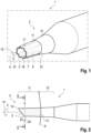
Figur 1 eine perspektivische Ansicht eines Injektors in einem entspannten Zustand schräg von vorne, -
Figur 2 eine Seitenansicht des Injektors in dem entspannten Zustand, -
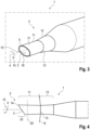
Figur 3 die Ansicht des Injektors gemäßFigur 1 in einem vollständig gespannten Zustand des Injektors, -
Figur 4 die Ansicht des Injektors gemäßFigur 2 in dem vollständig gespannten Zustand, -
Figur 5 einen Längsschnitt durch eine bevorzugte Ausführungsform des Injektors, -
Figur 6 einen Querschnitt entlang der inFigur 2 eingezeichneten Ebene A-A durch eine Injektorspitze des Injektors und -
Figur 7 eine schematische Darstellung eines Längsschnittes des inFigur 1 gezeigten Injektors. - Wie es aus
Figuren 1 bis 7 ersichtlich ist, weist ein Injektor 1 für ein Einführen einer Intraokularlinse 21 in den Kapselsack eines Auges eine Injektorachse 4, eine Injektorspitze 2, die eine Öffnung 3 und eine die Öffnung 3 begrenzende Wand 5 aufweist, und einen Kolben 19 auf, der in Richtung der Injektorachse 4 längsverlagerbar in dem Injektor 1 gelagert ist und eingerichtet ist, die Intraokularlinse 21 via die Öffnung 3 aus dem Injektor 1 zu befördern, wobei die Wand 5 in einem ersten Abschnitt 11, der von dem Ende 14 der Injektorspitze 2, an dem die Öffnung 3 angeordnet ist, ausgeht und sich in Richtung der Injektorachse 4 erstreckt, einen Elastizitätsmodul unter einer Zugbelastung in einem Bereich von 10 N/mm2 bis 500 N/mm2 hat und gewellt ausgeführt ist, so dass die Wand 5 in einer Querschnittsebene 20, deren Normale parallel zu der Injektorachse 4 angeordnet ist, eine Mehrzahl von Bergen 6 und eine Mehrzahl von Tälern 7 aufweist, wobei die Berge 6 und die Täler 7 in Umfangsrichtung 10 bezüglich der Injektorachse 4 abwechselnd angeordnet sind.Figur 1 zeigt, dass die Täler 7 in Richtung von der Öffnung 3 weg kontinuierlich immer flacher ausgebildet sein können.Figur 7 zeigt, dass der Injektor 1 die Intraokularlinse 21 aufweisen kann. -
Figuren 2 bis 5 zeigen, dass die Injektorspitze 2 in dem Bereich des Endes 14 abgeschrägt sein kann. Beispielsweise kann die Wand 5 eine Stirnfläche 15 haben, die unmittelbar an die Öffnung 3 angrenzt und deren Normale einen Winkel mit der Injektorachse 4 einschließt, der von 0° verschieden ist und der beispielsweise von 20° bis 70° oder von 40° bis 50° beträgt. In dem Fall, dass die Injektorspitze 2 abgeschrägt ist, kann die Querschnittsebene 20 abseits desjenigen Bereichs 22, in dem die Injektorspitze 2 abgeschrägt ist, angeordnet sein.Figur 6 zeigt, dass die Wand 5 in der Querschnittsebene 20 und in Umfangsrichtung 10 bezüglich der Injektorachse 4 ohne Unterbrechungen ausgeführt sein kann. Zudem ist ersichtlich, dass die Wand 5 in der Querschnittsebene 20 und in Umfangsrichtung 10 bezüglich der Injektorachse 4 eine konstante Dicke 16 haben kann. Es ist zudem denkbar, dass die Dicke 16 in dem vollständigen ersten Abschnitt 11 konstant sein kann.Figur 6 zeigt zudem, dass die Wand 5 in der Querschnittsebene 20 und somit normal zur Injektorachse 4 punktsymmetrisch ausgeführt sein kann. - Insbesondere aus
Figuren 1 und3 ist ersichtlich, dass die Öffnung 3 vollständig in einer Öffnungsebene, die parallel zu der Querschnittsebene angeordnet sein kann oder deren Normale mit der Normalen der Querschnittsebene einen von 0° verschiedenen Winkel einschließen kann, liegen kann und dass die Wand 5 in dem ersten Abschnitt 11 bis auf die Öffnung 3 keine weiteren Aussparungen aufweisen kann. Zudem kann die Stirnfläche 15 vollständig in der Öffnungsebene liegen. - Die Wand 5 kann jeweils acht der Berge 6 und der Täler 7 aufweisen, wie es beispielsweise aus
Figuren 1 und6 ersichtlich ist. Es ist auch denkbar, dass die Wand 5 jeweils von vier bis zwölf der Berge 6 und der Täler 7 aufweist, insbesondere jeweils von sechs bis zehn der Berge 6 und der Täler 7. - Die Injektorspitze 4 kann einen entspannten Zustand, der in
Figuren 1, 2 und6 dargestellt ist und in dem die Intraokularlinse nicht in der Injektorspitze 4 angeordnet ist, einen teilweise gespannten Zustand, in dem die Wand 5 in dem ersten Abschnitt 11 durch ein Einführen der Intraokularlinse in die Injektorspitze 2 unter eine mechanische Spannung gesetzt ist, und einen maximal gespannten Zustand aufweisen, der inFiguren 3 bis 5 dargestellt ist und in dem die Wand 5 durch das Einführen der Intraokularlinse maximal gespannt ist, wobei die Öffnung 3 in dem maximal gespannten Zustand größer als in dem entspannten Zustand ist. Der besseren Übersicht halber ist eine die mechanische Spannung des ersten Abschnittes 11 verursachende Intraokularlinse 21 nicht eingezeichnet. Die Wand 5 kann eingerichtet sein, dass die Injektorspitze 2 wieder in den inFiguren 1, 2 und6 dargestellten entspannten Zustand zurückkehrt, nachdem die Intraokularlinse 21 den Injektor 1 verlassen hat. -
Figur 2 zeigt, dass in dem ersten Abschnitt 11 die Injektorspitze 2 in Richtung zu der Öffnung 3 hin ihren Querschnitt, dessen Normale parallel zu der Injektorachse 4 angeordnet ist, in dem entspannten Zustand verkleinern kann. -
Figur 4 zeigt, dass in dem ersten Abschnitt 11 die Injektorspitze 2 in Richtung zu der Öffnung 3 hin ihren Querschnitt, dessen Normale parallel zu der Injektorachse 4 angeordnet ist, in dem maximal gespannten Zustand vergrößern kann. Alternativ ist denkbar, dass in dem ersten Abschnitt 11 die Injektorspitze 2 in Richtung zu der Öffnung 3 hin ihren Querschnitt, dessen Normale parallel zu der Injektorachse 4 angeordnet ist, in dem maximal gespannten Zustand gleich groß belassen kann. Dabei kann jeweils der Querschnitt an der Innenseite 18 der Wand 5 und/oder an der Außenseite 17 der Wand gemeint sein. In dem ersten Abschnitt 11 kann die Wand 5 an deren Außenseite 17 und/oder deren Innenseite 18 in der Querschnittsebene 20 und in dem maximal gespannten Zustand beispielsweise eine kreisförmige, elliptische und/oder ovale Form haben. - Wie es aus
Figuren 1 bis 5 ersichtlich ist, kann die Wand 5 einen zweiten Abschnitt 12 aufweisen, der sich in Richtung der Injektorachse 4 erstreckt und in dem die Wand 5 ein Elastizitätsmodul unter der Zugbelastung von höher als 900 N/mm2 hat und nicht gewellt ist. Der zweite Abschnitt 12 kann dabei unmittelbar an den ersten Abschnitt 11 angrenzen, wie es auch dieFiguren 1 bis 5 zeigen. Dabei ist denkbar, dass die Wand 5 in dem gesamten ersten Abschnitt 1 einen Elastizitätsmodul unter der Zugbelastung im Bereich von 10 N/mm2 bis 500 N/mm2 hat. Zudem ist denkbar, dass die Wand 5 in dem gesamten ersten Abschnitt 11 gewellt ausgeführt ist. Alternativ ist denkbar, dass die Wand 5 lediglich in einem Bereich, der unmittelbar an den zweiten Abschnitt 12 angrenzt, nicht gewellt ausgeführt ist, wie es beispielsweise ausFigur 1 ersichtlich ist. - Der zweite Abschnitt 12 und/oder eine Grenze zwischen dem ersten Abschnitt 11 und dem zweiten Abschnitt 12 sind dazu vorgesehen, eine Hornhaut 8 des Auges zu kontaktieren, wenn die Injektorspitze 2 in das Auge eingeführt wird (vergleiche
Figuren 2 und4 ). Die Injektorspitze 2 kann eine Markierung 13 aufweisen, um die Grenze zwischen dem ersten Abschnitt 11 und dem zweiten Abschnitt 12 zu kennzeichnen (sieheFiguren 1 bis 4 ) . - Die Wand 5 in dem zweiten Abschnitt 12 kann somit einen Elastizitätsmodul unter der Zugbelastung von höher als 900 N/mm2 haben. Alternativ dazu kann die Dicke 16 der Wand 5 in dem zweiten Abschnitt 12 größer als in dem ersten Abschnitt sein, wobei der Elastizitätsmodul jenem des ersten Abschnitts entspricht. Alternativ oder zusätzlich kann der zweite Abschnitt 12 ein Verstärkungsstück aufweisen, das in der Wand 5 angeordnet ist.
Figur 5 , in der die Injektorspitze 2 im Längsschnitt und das Verstärkungsstück vollständig dargestellt ist, zeigt, dass das Verstärkungsstück eine Helix 9 sein kann. Die Steigung der Helix 9 kann dabei entlang der Injektorachse 4 variieren. Alternativ ist denkbar, dass das Verstärkungsstück die Helix 9 aufweist, ein zylindermantelförmiges Teil ist oder aufweist und/oder ein kegelmantelförmiges Teil ist oder aufweist. Die Helix 9 hat den Vorteil, dass ein Bediener in dem Fall, dass die Wand 5 transparent ist, in die Injektorspitze 2 hinein sehen kann und ein Verlagern der Intraokularlinse 21 kontrollieren kann. Das zylindermantelförmige Teil und das kegelmantelförmige Teil haben den Vorteil, dass sie den zweiten Abschnitt besonders gut versteifen können. Das Verstärkungsstück kann ein Metall oder eine Legierung aufweisen oder aus dem Metall oder der Legierung bestehen.Figur 5 zeigt zudem, dass die Dicke 16 der Wand 5 in dem ersten Abschnitt 11 gleich der Dicke der Wand 5 in dem zweiten Abschnitt 12 sein kann. - Die Injektorspitze 2 mit dem Verstärkungsstück kann beispielsweise durch ein Spritzgussverfahren hergestellt werden. Alternativ ist denkbar, dass die Injektorspitze 2 mit dem Verstärkungsstück hergestellt wird, indem ein Rohr aus einem polymeren Werkstoff extrudiert wird, auf das Rohr das Verstärkungsstück aufgebracht wird, insbesondere die Spirale aufgewickelt wird, und danach eine äußere Schicht aus einem polymeren Werkstoff auf das Rohr und das Verstärkungsstück aufgebracht wird. Zudem kann vor dem Aufbringen des Verstärkungsstücks eine Klebeschicht außen auf das Rohr aufgebracht werden.
-
- 1
- Injektor
- 2
- Injektorspitze
- 3
- Öffnung
- 4
- Injektorachse
- 5
- Wand
- 6
- Berg
- 7
- Tal
- 8
- Hornhaut
- 9
- Helix
- 10
- Umfangsrichtung
- 11
- erster Abschnitt
- 12
- zweiter Abschnitt
- 13
- Markierung
- 14
- Ende
- 15
- Stirnfläche
- 16
- Dicke
- 17
- Außenseite
- 18
- Innenseite
- 19
- Kolben
- 20
- Querschnittsebene
- 21
- Intraokularlinse
- 22
- abgeschrägter Bereich
Claims (9)
- Injektor für ein Einführen einer Intraokularlinse in den Kapselsack eines Auges, mit einer Injektorachse (4), einer Injektorspitze (2), die eine Öffnung (3) und eine die Öffnung (3) begrenzende Wand (5) aufweist, einem Kolben (19), der in Richtung der Injektorachse (4) längsverlagerbar in dem Injektor (1) gelagert ist und eingerichtet ist, die Intraokularlinse via die Öffnung (3) aus dem Injektor (1) zu befördern, wobei die Wand (5) in einem ersten Abschnitt (11), der von dem Ende (14) der Injektorspitze (2), an dem die Öffnung (3) angeordnet ist, ausgeht und sich in Richtung der Injektorachse (4) erstreckt, einen Elastizitätsmodul unter einer Zugbelastung in einem Bereich von 10 N/mm2 bis 500 N/mm2 hat und gewellt ausgeführt ist, so dass die Wand (5) in einer Querschnittsebene (20), deren Normale parallel zu der Injektorachse (4) angeordnet ist, eine Mehrzahl von Bergen (6) und eine Mehrzahl von Tälern (7) aufweist, wobei die Berge (6) und die Täler (7) in Umfangsrichtung (10) bezüglich der Injektorachse (4) abwechselnd angeordnet sind, dadurch gekennzeichnet, dass die Injektorspitze (2) in dem Bereich des Endes (14) abgeschrägt ist, indem die Wand (5) eine Stirnfläche (15) hat, die unmittelbar an die Öffnung (3) angrenzt und deren Normale einen Winkel mit der Injektorachse (4) einschließt, der von 0° verschieden ist.
- Injektor gemäß Anspruch 1, wobei die Injektorspitze (4) einen entspannten Zustand, in dem die Intraokularlinse nicht in der Injektorspitze (4) angeordnet ist, einen teilweise gespannten Zustand, in dem die Wand (5) in dem ersten Abschnitt (11) durch ein Einführen der Intraokularlinse in die Injektorspitze (2) unter eine mechanische Spannung gesetzt ist, und einen maximal gespannten Zustand aufweist, in dem die Wand (5) durch das Einführen der Intraokularlinse maximal gespannt ist, wobei die Öffnung (3) in dem maximal gespannten Zustand größer als in dem entspannten Zustand ist.
- Injektor gemäß Anspruch 2, wobei in dem ersten Abschnitt (11) die Injektorspitze (2) in Richtung zu der Öffnung (3) hin ihren Querschnitt, dessen Normale parallel zu der Injektorachse (4) angeordnet ist, in dem entspannten Zustand verkleinert.
- Injektor gemäß Anspruch 2 oder 3, wobei in dem ersten Abschnitt (11) die Injektorspitze (2) in Richtung zu der Öffnung (3) hin ihren Querschnitt, dessen Normale parallel zu der Injektorachse (4) angeordnet ist, in dem maximal gespannten Zustand vergrößert oder gleich groß belässt.
- Injektor gemäß einem der Ansprüche 2 bis 4, wobei in dem ersten Abschnitt (11) die Wand (5) an deren Außenseite (17) und/oder deren Innenseite (18) in der Querschnittsebene (20) und in dem maximal gespannten Zustand eine kreisförmige, elliptische und/oder ovale Form hat.
- Injektor gemäß einem der Ansprüche 1 bis 5, wobei die Wand (5) in Umfangsrichtung (10) bezüglich der Injektorachse (4) eine konstante Dicke (16) hat.
- Injektor gemäß einem der Ansprüche 1 bis 6, wobei die Wand (5) einen zweiten Abschnitt (12) aufweist, der sich in Richtung der Injektorachse (4) erstreckt und in dem die Wand (5) einen Elastizitätsmodul unter der Zugbelastung von höher als 900 N/mm2 hat.
- Injektor gemäß Anspruch 7, wobei der zweite Abschnitt (12) ein Verstärkungsstück aufweist, das in der Wand (5) angeordnet ist, wobei das Verstärkungsstück eine Helix (9), ein zylindermantelförmiges Teil und/oder einen kegelmantelförmiges Teil ist oder aufweist.
- Injektor gemäß einem der Ansprüche 1 bis 8, wobei die Wand (5) jeweils von vier bis zwölf der Berge (6) und der Täler (7) aufweist, insbesondere jeweils von sechs bis zehn der Berge (6) und der Täler (7) oder jeweils acht der Berge (6) und der Täler (7) aufweist.
Applications Claiming Priority (2)
| Application Number | Priority Date | Filing Date | Title |
|---|---|---|---|
| DE102021115562.2A DE102021115562A1 (de) | 2021-06-16 | 2021-06-16 | Injektor mit einer eine gewellte Wand aufweisenden Injektorspitze |
| PCT/EP2022/065124 WO2022263200A1 (de) | 2021-06-16 | 2022-06-02 | Injektor mit einer eine gewellte wand aufweisenden injektorspitze |
Publications (2)
| Publication Number | Publication Date |
|---|---|
| EP4355263A1 EP4355263A1 (de) | 2024-04-24 |
| EP4355263B1 true EP4355263B1 (de) | 2024-11-27 |
Family
ID=82163581
Family Applications (1)
| Application Number | Title | Priority Date | Filing Date |
|---|---|---|---|
| EP22732970.3A Active EP4355263B1 (de) | 2021-06-16 | 2022-06-02 | Injektor mit einer eine gewellte wand aufweisenden injektorspitze |
Country Status (3)
| Country | Link |
|---|---|
| EP (1) | EP4355263B1 (de) |
| DE (1) | DE102021115562A1 (de) |
| WO (1) | WO2022263200A1 (de) |
Family Cites Families (4)
| Publication number | Priority date | Publication date | Assignee | Title |
|---|---|---|---|---|
| US6056757A (en) | 1992-09-30 | 2000-05-02 | Staar Surgical Company, Inc. | Implantation device with deformable nozzle tip for implanting a deformable intraocular lens |
| JP3861138B2 (ja) * | 2001-09-04 | 2006-12-20 | キヤノンスター株式会社 | 眼内レンズの挿入器具 |
| US20070005135A1 (en) * | 2005-07-01 | 2007-01-04 | Harish Makker | Intraocular lens insertion plunger with low stimulus soft tip |
| JP5520417B2 (ja) | 2010-04-22 | 2014-06-11 | シュリカント ミルライ ラム | 改良された眼内レンズ注入デバイス |
-
2021
- 2021-06-16 DE DE102021115562.2A patent/DE102021115562A1/de active Pending
-
2022
- 2022-06-02 EP EP22732970.3A patent/EP4355263B1/de active Active
- 2022-06-02 WO PCT/EP2022/065124 patent/WO2022263200A1/de not_active Ceased
Also Published As
| Publication number | Publication date |
|---|---|
| DE102021115562A1 (de) | 2022-12-22 |
| EP4355263A1 (de) | 2024-04-24 |
| WO2022263200A1 (de) | 2022-12-22 |
Similar Documents
| Publication | Publication Date | Title |
|---|---|---|
| DE60319176T2 (de) | Vorrichtung zum Einsetzen einer Intraokularlinse | |
| DE69417098T2 (de) | Biologisch abbaubarer medullärer Pfropfen | |
| DE60221365T2 (de) | Injektor für eine intraokularlinse | |
| EP1893272B1 (de) | Einführhilfe für die perkutane tracheostomie | |
| DE60119751T2 (de) | Einführungsvorrichtung zum implantieren einer weichen intraokularlinse | |
| EP3088018A1 (de) | Rotor für eine fluidpumpe sowie verfahren und giessform für seine herstellung | |
| EP2349092B1 (de) | Vorrichtung zum implantieren einer intraokularlinse in ein auge | |
| EP3363345B1 (de) | Endoskop, endoskopkopf sowie verfahren zum herstellen eines endoskops | |
| EP4355263B1 (de) | Injektor mit einer eine gewellte wand aufweisenden injektorspitze | |
| DE102014114888A1 (de) | Stent für die perkutane Vertebroplastie | |
| DE102015117666B4 (de) | Endovaskuläre, medizinische Vorrichtung, Behandlungssystem mit einer solchen Vorrichtung und Herstellungsverfahren | |
| DE20010879U1 (de) | Biopsienadel mit Entnahmesystem | |
| EP4216873A1 (de) | Kolben für einen injektor und injektor | |
| EP2821042A1 (de) | Tamponapplikator und Verfahren zur Montage | |
| DE202020103402U1 (de) | Tupfer zur Entnahme von Sekret von oder aus einem menschlichen oder tierischen Körper | |
| DE102021117965B4 (de) | Injektor mit einer eine Mehrzahl an Armen aufweisenden Kolbenspitze | |
| DE202009016524U1 (de) | Kanüle und Kanülenvorrichtung zum Implantieren eines Implantats | |
| DE102020122597B3 (de) | Ophthalmochirurgischer Injektor | |
| DE102016200434A1 (de) | Kolbenstange für medizinische Packmittel | |
| DE102020109867B4 (de) | Intraokularlinsen-Injektor mit spezifischer Einstechspitze einer Hohlnadel | |
| DE102021006544A1 (de) | Injektor mit einer eine Mehrzahl an Armen aufweisenden Kolbenspitze | |
| DE102021006549A1 (de) | Injektor mit einer eine Mehrzahl an Armen aufweisenden Kolbenspitze | |
| EP3569282B1 (de) | Ventil mit vorgefertigter komprimierter dilatierbarer öffnung | |
| DE102016111839B3 (de) | Instrument zur apikalen Aufbereitung eines Wurzelkanals | |
| DE102023126600A1 (de) | Injektor mit einer in einer Injektorspitze wendelförmig verlaufenden Nut |
Legal Events
| Date | Code | Title | Description |
|---|---|---|---|
| STAA | Information on the status of an ep patent application or granted ep patent |
Free format text: STATUS: UNKNOWN |
|
| STAA | Information on the status of an ep patent application or granted ep patent |
Free format text: STATUS: THE INTERNATIONAL PUBLICATION HAS BEEN MADE |
|
| PUAI | Public reference made under article 153(3) epc to a published international application that has entered the european phase |
Free format text: ORIGINAL CODE: 0009012 |
|
| STAA | Information on the status of an ep patent application or granted ep patent |
Free format text: STATUS: REQUEST FOR EXAMINATION WAS MADE |
|
| 17P | Request for examination filed |
Effective date: 20231215 |
|
| AK | Designated contracting states |
Kind code of ref document: A1 Designated state(s): AL AT BE BG CH CY CZ DE DK EE ES FI FR GB GR HR HU IE IS IT LI LT LU LV MC MK MT NL NO PL PT RO RS SE SI SK SM TR |
|
| GRAP | Despatch of communication of intention to grant a patent |
Free format text: ORIGINAL CODE: EPIDOSNIGR1 |
|
| STAA | Information on the status of an ep patent application or granted ep patent |
Free format text: STATUS: GRANT OF PATENT IS INTENDED |
|
| DAV | Request for validation of the european patent (deleted) | ||
| DAX | Request for extension of the european patent (deleted) | ||
| INTG | Intention to grant announced |
Effective date: 20240717 |
|
| GRAS | Grant fee paid |
Free format text: ORIGINAL CODE: EPIDOSNIGR3 |
|
| GRAA | (expected) grant |
Free format text: ORIGINAL CODE: 0009210 |
|
| STAA | Information on the status of an ep patent application or granted ep patent |
Free format text: STATUS: THE PATENT HAS BEEN GRANTED |
|
| P01 | Opt-out of the competence of the unified patent court (upc) registered |
Free format text: CASE NUMBER: APP_55856/2024 Effective date: 20241011 |
|
| AK | Designated contracting states |
Kind code of ref document: B1 Designated state(s): AL AT BE BG CH CY CZ DE DK EE ES FI FR GB GR HR HU IE IS IT LI LT LU LV MC MK MT NL NO PL PT RO RS SE SI SK SM TR |
|
| REG | Reference to a national code |
Ref country code: GB Ref legal event code: FG4D Free format text: NOT ENGLISH |
|
| REG | Reference to a national code |
Ref country code: CH Ref legal event code: EP |
|
| REG | Reference to a national code |
Ref country code: IE Ref legal event code: FG4D Free format text: LANGUAGE OF EP DOCUMENT: GERMAN |
|
| REG | Reference to a national code |
Ref country code: DE Ref legal event code: R096 Ref document number: 502022002251 Country of ref document: DE |
|
| REG | Reference to a national code |
Ref country code: LT Ref legal event code: MG9D |
|
| REG | Reference to a national code |
Ref country code: NL Ref legal event code: MP Effective date: 20241127 |
|
| PG25 | Lapsed in a contracting state [announced via postgrant information from national office to epo] |
Ref country code: IS Free format text: LAPSE BECAUSE OF FAILURE TO SUBMIT A TRANSLATION OF THE DESCRIPTION OR TO PAY THE FEE WITHIN THE PRESCRIBED TIME-LIMIT Effective date: 20250327 Ref country code: HR Free format text: LAPSE BECAUSE OF FAILURE TO SUBMIT A TRANSLATION OF THE DESCRIPTION OR TO PAY THE FEE WITHIN THE PRESCRIBED TIME-LIMIT Effective date: 20241127 Ref country code: PT Free format text: LAPSE BECAUSE OF FAILURE TO SUBMIT A TRANSLATION OF THE DESCRIPTION OR TO PAY THE FEE WITHIN THE PRESCRIBED TIME-LIMIT Effective date: 20250327 |
|
| PG25 | Lapsed in a contracting state [announced via postgrant information from national office to epo] |
Ref country code: FI Free format text: LAPSE BECAUSE OF FAILURE TO SUBMIT A TRANSLATION OF THE DESCRIPTION OR TO PAY THE FEE WITHIN THE PRESCRIBED TIME-LIMIT Effective date: 20241127 Ref country code: NL Free format text: LAPSE BECAUSE OF FAILURE TO SUBMIT A TRANSLATION OF THE DESCRIPTION OR TO PAY THE FEE WITHIN THE PRESCRIBED TIME-LIMIT Effective date: 20241127 |
|
| PG25 | Lapsed in a contracting state [announced via postgrant information from national office to epo] |
Ref country code: BG Free format text: LAPSE BECAUSE OF FAILURE TO SUBMIT A TRANSLATION OF THE DESCRIPTION OR TO PAY THE FEE WITHIN THE PRESCRIBED TIME-LIMIT Effective date: 20241127 |
|
| PG25 | Lapsed in a contracting state [announced via postgrant information from national office to epo] |
Ref country code: ES Free format text: LAPSE BECAUSE OF FAILURE TO SUBMIT A TRANSLATION OF THE DESCRIPTION OR TO PAY THE FEE WITHIN THE PRESCRIBED TIME-LIMIT Effective date: 20241127 |
|
| PG25 | Lapsed in a contracting state [announced via postgrant information from national office to epo] |
Ref country code: NO Free format text: LAPSE BECAUSE OF FAILURE TO SUBMIT A TRANSLATION OF THE DESCRIPTION OR TO PAY THE FEE WITHIN THE PRESCRIBED TIME-LIMIT Effective date: 20250227 |
|
| PG25 | Lapsed in a contracting state [announced via postgrant information from national office to epo] |
Ref country code: GR Free format text: LAPSE BECAUSE OF FAILURE TO SUBMIT A TRANSLATION OF THE DESCRIPTION OR TO PAY THE FEE WITHIN THE PRESCRIBED TIME-LIMIT Effective date: 20250228 Ref country code: LV Free format text: LAPSE BECAUSE OF FAILURE TO SUBMIT A TRANSLATION OF THE DESCRIPTION OR TO PAY THE FEE WITHIN THE PRESCRIBED TIME-LIMIT Effective date: 20241127 |
|
| PG25 | Lapsed in a contracting state [announced via postgrant information from national office to epo] |
Ref country code: PL Free format text: LAPSE BECAUSE OF FAILURE TO SUBMIT A TRANSLATION OF THE DESCRIPTION OR TO PAY THE FEE WITHIN THE PRESCRIBED TIME-LIMIT Effective date: 20241127 |
|
| PG25 | Lapsed in a contracting state [announced via postgrant information from national office to epo] |
Ref country code: RS Free format text: LAPSE BECAUSE OF FAILURE TO SUBMIT A TRANSLATION OF THE DESCRIPTION OR TO PAY THE FEE WITHIN THE PRESCRIBED TIME-LIMIT Effective date: 20250227 |
|
| PG25 | Lapsed in a contracting state [announced via postgrant information from national office to epo] |
Ref country code: SM Free format text: LAPSE BECAUSE OF FAILURE TO SUBMIT A TRANSLATION OF THE DESCRIPTION OR TO PAY THE FEE WITHIN THE PRESCRIBED TIME-LIMIT Effective date: 20241127 |
|
| PGFP | Annual fee paid to national office [announced via postgrant information from national office to epo] |
Ref country code: DE Payment date: 20250618 Year of fee payment: 4 |
|
| PG25 | Lapsed in a contracting state [announced via postgrant information from national office to epo] |
Ref country code: DK Free format text: LAPSE BECAUSE OF FAILURE TO SUBMIT A TRANSLATION OF THE DESCRIPTION OR TO PAY THE FEE WITHIN THE PRESCRIBED TIME-LIMIT Effective date: 20241127 |
|
| PG25 | Lapsed in a contracting state [announced via postgrant information from national office to epo] |
Ref country code: EE Free format text: LAPSE BECAUSE OF FAILURE TO SUBMIT A TRANSLATION OF THE DESCRIPTION OR TO PAY THE FEE WITHIN THE PRESCRIBED TIME-LIMIT Effective date: 20241127 |
|
| PGFP | Annual fee paid to national office [announced via postgrant information from national office to epo] |
Ref country code: FR Payment date: 20250627 Year of fee payment: 4 |
|
| PG25 | Lapsed in a contracting state [announced via postgrant information from national office to epo] |
Ref country code: RO Free format text: LAPSE BECAUSE OF FAILURE TO SUBMIT A TRANSLATION OF THE DESCRIPTION OR TO PAY THE FEE WITHIN THE PRESCRIBED TIME-LIMIT Effective date: 20241127 |
|
| PGFP | Annual fee paid to national office [announced via postgrant information from national office to epo] |
Ref country code: AT Payment date: 20250721 Year of fee payment: 4 |
|
| PG25 | Lapsed in a contracting state [announced via postgrant information from national office to epo] |
Ref country code: SK Free format text: LAPSE BECAUSE OF FAILURE TO SUBMIT A TRANSLATION OF THE DESCRIPTION OR TO PAY THE FEE WITHIN THE PRESCRIBED TIME-LIMIT Effective date: 20241127 |
|
| PG25 | Lapsed in a contracting state [announced via postgrant information from national office to epo] |
Ref country code: CZ Free format text: LAPSE BECAUSE OF FAILURE TO SUBMIT A TRANSLATION OF THE DESCRIPTION OR TO PAY THE FEE WITHIN THE PRESCRIBED TIME-LIMIT Effective date: 20241127 |
|
| PG25 | Lapsed in a contracting state [announced via postgrant information from national office to epo] |
Ref country code: IT Free format text: LAPSE BECAUSE OF FAILURE TO SUBMIT A TRANSLATION OF THE DESCRIPTION OR TO PAY THE FEE WITHIN THE PRESCRIBED TIME-LIMIT Effective date: 20241127 |
|
| REG | Reference to a national code |
Ref country code: DE Ref legal event code: R097 Ref document number: 502022002251 Country of ref document: DE |
|
| PG25 | Lapsed in a contracting state [announced via postgrant information from national office to epo] |
Ref country code: SE Free format text: LAPSE BECAUSE OF FAILURE TO SUBMIT A TRANSLATION OF THE DESCRIPTION OR TO PAY THE FEE WITHIN THE PRESCRIBED TIME-LIMIT Effective date: 20241127 |
|
| PLBE | No opposition filed within time limit |
Free format text: ORIGINAL CODE: 0009261 |
|
| STAA | Information on the status of an ep patent application or granted ep patent |
Free format text: STATUS: NO OPPOSITION FILED WITHIN TIME LIMIT |
|
| PGFP | Annual fee paid to national office [announced via postgrant information from national office to epo] |
Ref country code: CH Payment date: 20250701 Year of fee payment: 4 |
|
| 26N | No opposition filed |
Effective date: 20250828 |
|
| PG25 | Lapsed in a contracting state [announced via postgrant information from national office to epo] |
Ref country code: MC Free format text: LAPSE BECAUSE OF FAILURE TO SUBMIT A TRANSLATION OF THE DESCRIPTION OR TO PAY THE FEE WITHIN THE PRESCRIBED TIME-LIMIT Effective date: 20241127 |
|
| PG25 | Lapsed in a contracting state [announced via postgrant information from national office to epo] |
Ref country code: LU Free format text: LAPSE BECAUSE OF NON-PAYMENT OF DUE FEES Effective date: 20250602 |
|
| REG | Reference to a national code |
Ref country code: BE Ref legal event code: MM Effective date: 20250630 |
|
| PG25 | Lapsed in a contracting state [announced via postgrant information from national office to epo] |
Ref country code: IE Free format text: LAPSE BECAUSE OF NON-PAYMENT OF DUE FEES Effective date: 20250602 |
|
| PG25 | Lapsed in a contracting state [announced via postgrant information from national office to epo] |
Ref country code: BE Free format text: LAPSE BECAUSE OF NON-PAYMENT OF DUE FEES Effective date: 20250630 |