EP4355932B1 - System zur elektrokatalytischen umwandlung von kohlenstoffoxiden in mehrkohlenstoffprodukte unter verwendung einer stationären katholytschicht und zugehöriges verfahren - Google Patents
System zur elektrokatalytischen umwandlung von kohlenstoffoxiden in mehrkohlenstoffprodukte unter verwendung einer stationären katholytschicht und zugehöriges verfahren Download PDFInfo
- Publication number
- EP4355932B1 EP4355932B1 EP22735366.1A EP22735366A EP4355932B1 EP 4355932 B1 EP4355932 B1 EP 4355932B1 EP 22735366 A EP22735366 A EP 22735366A EP 4355932 B1 EP4355932 B1 EP 4355932B1
- Authority
- EP
- European Patent Office
- Prior art keywords
- catholyte
- layer
- solution
- stationary
- cathode
- Prior art date
- Legal status (The legal status is an assumption and is not a legal conclusion. Google has not performed a legal analysis and makes no representation as to the accuracy of the status listed.)
- Active
Links
Images





Classifications
-
- C—CHEMISTRY; METALLURGY
- C25—ELECTROLYTIC OR ELECTROPHORETIC PROCESSES; APPARATUS THEREFOR
- C25B—ELECTROLYTIC OR ELECTROPHORETIC PROCESSES FOR THE PRODUCTION OF COMPOUNDS OR NON-METALS; APPARATUS THEREFOR
- C25B3/00—Electrolytic production of organic compounds
- C25B3/01—Products
- C25B3/03—Acyclic or carbocyclic hydrocarbons
-
- C—CHEMISTRY; METALLURGY
- C25—ELECTROLYTIC OR ELECTROPHORETIC PROCESSES; APPARATUS THEREFOR
- C25B—ELECTROLYTIC OR ELECTROPHORETIC PROCESSES FOR THE PRODUCTION OF COMPOUNDS OR NON-METALS; APPARATUS THEREFOR
- C25B11/00—Electrodes; Manufacture thereof not otherwise provided for
- C25B11/02—Electrodes; Manufacture thereof not otherwise provided for characterised by shape or form
- C25B11/03—Electrodes; Manufacture thereof not otherwise provided for characterised by shape or form perforated or foraminous
- C25B11/031—Porous electrodes
- C25B11/032—Gas diffusion electrodes
-
- C—CHEMISTRY; METALLURGY
- C25—ELECTROLYTIC OR ELECTROPHORETIC PROCESSES; APPARATUS THEREFOR
- C25B—ELECTROLYTIC OR ELECTROPHORETIC PROCESSES FOR THE PRODUCTION OF COMPOUNDS OR NON-METALS; APPARATUS THEREFOR
- C25B13/00—Diaphragms; Spacing elements
- C25B13/02—Diaphragms; Spacing elements characterised by shape or form
-
- C—CHEMISTRY; METALLURGY
- C25—ELECTROLYTIC OR ELECTROPHORETIC PROCESSES; APPARATUS THEREFOR
- C25B—ELECTROLYTIC OR ELECTROPHORETIC PROCESSES FOR THE PRODUCTION OF COMPOUNDS OR NON-METALS; APPARATUS THEREFOR
- C25B13/00—Diaphragms; Spacing elements
- C25B13/04—Diaphragms; Spacing elements characterised by the material
- C25B13/08—Diaphragms; Spacing elements characterised by the material based on organic materials
-
- C—CHEMISTRY; METALLURGY
- C25—ELECTROLYTIC OR ELECTROPHORETIC PROCESSES; APPARATUS THEREFOR
- C25B—ELECTROLYTIC OR ELECTROPHORETIC PROCESSES FOR THE PRODUCTION OF COMPOUNDS OR NON-METALS; APPARATUS THEREFOR
- C25B15/00—Operating or servicing cells
- C25B15/08—Supplying or removing reactants or electrolytes; Regeneration of electrolytes
-
- C—CHEMISTRY; METALLURGY
- C25—ELECTROLYTIC OR ELECTROPHORETIC PROCESSES; APPARATUS THEREFOR
- C25B—ELECTROLYTIC OR ELECTROPHORETIC PROCESSES FOR THE PRODUCTION OF COMPOUNDS OR NON-METALS; APPARATUS THEREFOR
- C25B3/00—Electrolytic production of organic compounds
- C25B3/01—Products
- C25B3/07—Oxygen containing compounds
-
- C—CHEMISTRY; METALLURGY
- C25—ELECTROLYTIC OR ELECTROPHORETIC PROCESSES; APPARATUS THEREFOR
- C25B—ELECTROLYTIC OR ELECTROPHORETIC PROCESSES FOR THE PRODUCTION OF COMPOUNDS OR NON-METALS; APPARATUS THEREFOR
- C25B3/00—Electrolytic production of organic compounds
- C25B3/20—Processes
- C25B3/25—Reduction
-
- C—CHEMISTRY; METALLURGY
- C25—ELECTROLYTIC OR ELECTROPHORETIC PROCESSES; APPARATUS THEREFOR
- C25B—ELECTROLYTIC OR ELECTROPHORETIC PROCESSES FOR THE PRODUCTION OF COMPOUNDS OR NON-METALS; APPARATUS THEREFOR
- C25B3/00—Electrolytic production of organic compounds
- C25B3/20—Processes
- C25B3/25—Reduction
- C25B3/26—Reduction of carbon dioxide
-
- C—CHEMISTRY; METALLURGY
- C25—ELECTROLYTIC OR ELECTROPHORETIC PROCESSES; APPARATUS THEREFOR
- C25B—ELECTROLYTIC OR ELECTROPHORETIC PROCESSES FOR THE PRODUCTION OF COMPOUNDS OR NON-METALS; APPARATUS THEREFOR
- C25B9/00—Cells or assemblies of cells; Constructional parts of cells; Assemblies of constructional parts, e.g. electrode-diaphragm assemblies; Process-related cell features
- C25B9/17—Cells comprising dimensionally-stable non-movable electrodes; Assemblies of constructional parts thereof
- C25B9/19—Cells comprising dimensionally-stable non-movable electrodes; Assemblies of constructional parts thereof with diaphragms
Definitions
- the interfacial layer can comprise a water dissociation catalyst; with preference that the water dissociation catalyst comprises one or more selected from TiO 2 , IrO 2 , NiO, SnO 2 , graphene oxide, CoOx, ZrO 2 , Al 2 O 3 , Fe(OH) 3 , MnO 2 , Ru, Rh, RuPt alloy, Ptlr alloy, Ir, Pt. More preferably, the water dissociation catalyst can be a combination of IrO 2 on the AEL side) and NiO on the CEL side. In an embodiment, the water dissociation catalyst is present as nanoparticles.
- the CEL is a Nafion TM membrane (CAS number 31175-20-9)
- the process uses the system described above.
- this porous stationary layer allows for improving the mass transport efficiency of the in-situ recovered CO 2 to catalyst (quantitatively simulated in section SI3 of Supplemental Information provided further below) in comparison to known systems.
- the composition of the stationary catholyte layer greatly impacts CO 2 RR performance in SC-MEA (analyzed and rationalized in sections SI2 and SI3 of Supplemental Information provided further below).
- the catholyte solution can be designed as a non-buffered catholyte solution, e.g. K 2 SO 4 , in order to introduce cation effects as a means to promote selectivity to CO 2 RR over HER (see references 25 and 26).
- the anolyte solution has an anolyte concentration between 2.0 M and 0.01M; for example, between 1.5 M and 0.05M; for example, between 1.0 M and 0.08 M; for example, between 0.5 M and 0.1 M.
- the anolyte solution has an anolyte concentration of about 0.1 M.
- the anolyte solution is neutral.
- the anolyte solution has a pH between 7.0 and 10.0; preferably a pH between 7.5 and 9.5.
- the anolyte (neutral) solution is a KHCO 3 , K 2 SO 4 , or K 2 HPO 4 solution.
- the anolyte solution is acidic.
- the anolyte solution has a pH between 1.0 and 4.0; for example, between 1.5 and 3.5; for example, between 2.0 and 3.0.
- the acidic solution is an H 3 PO 4 solution, H 2 SO 4 solution or a combination thereof.
- Proton-induced CO 2 regeneration could also be accomplished by coupling a cation-exchange membrane and acidic anolyte since the anodic OER can supply protons. It was observed that the CO 2 crossover in this system is below the detection limits. However, the experimental and theoretical analyzes showed that this system does not operate continuously because of co-ion transport and water balance issues (discussed in SI3 of Supplemental Information).
- a CO 2 /O 2 ratio of an anodic gas mixture (also referred to as an anode gas) was further studied to evaluate the capability to prohibit CO 2 crossover in the BPM-based SC-MEA, the key to achieving a high SPU (SI1) (see references 13 and 14).
- SI1 high SPU
- the AEM-based MEA showed CO 2 /O 2 ratios very close to 2 for current densities from 100 to 300 mA.cm -2 ( Figure 2D ), indicating that the majority of the anionic charge carrier in AEM-based MEA is CO 3 2- , which causes ca. one molecule of CO 2 loss per two electrons transferred.
- FIG. 2E shows FEs of gas products at the cathode within a given range of CO 2 feed rates ( Figure 2C ). Lowering the CO 2 flow rate from 15 ( Figure 3a) to 8 sccm ( Figure 3b ) was shown not to cause a significant change in the gas product distribution.
- the SPU of SC-MEA increases from 23% (8 sccm) to 61% (1 sccm), exceeding the upper limit of the SPU for the ordinary electrolyzers producing fully CO (50%) or fully C 2+ (excluding acetate) products (25%), and is also higher than the state-of-art reported SPU (30%) for producing C 2+ products (see reference 15).
- the upper limit of SPU for an AEM-based electrolyzer was also simulated.
- the upper limit of the resulting SPU should be in the range of 13% to 15% (red zone in Figure 2F , simulation details in section SI1 of Supplemental Information).
- Acidic anolyte further suppresses CO 2 crossover
- a simulated AEM-based MEA showed an SPU of 15 ⁇ 1%.
- Table 1 Summary of energy penalty associated with CO 2 recovery energy consumption for SC-MEA, simulated AEM-based MEA (Figure 3C), and benchmark neutral media AEM-based MEA electrolyzer from literature.
- Table 1 summarizes and compares the CO 2 recovery energy consumptions of the SC-MEA (acidic anolyte), and the literature benchmark neutral media AEM-based MEA electrolyzer (see reference 15). Coupling the advantages of minimized CO 2 crossover (enabled by BPM) and acidic bulk anolyte solution, the present BPM-based SC-MEA can allow a 86% and 72% reduction in energy penalty associated with CO 2 recovery compared to the simulated MEA electrolyzer and literature benchmark neutral media electrolyzer 15, respectively. These results highlight the need for high-SPU CO 2 RR devices, i.e., lower energy consumption.
- the SC-MEA was less stable than the ones fed by 9 sccm CO 2 - the C 2+ FE dropped by ca. 37% after 5 hours accompanied by decreased SPU.
- the products could be carried out by unreacted CO 2 .
- the mass exchange efficiency can be lower than the 9 sccm cases, which can lead to the over-accumulation of CO 2 RR products and consequently lower the activity of Cu catalyst (see references 30 to 32).
- This over-accumulation issue is a newly discovered challenge in high-SPU electrolyzers, calling for innovations of system design and catalyst in the future. Nevertheless, throughout the 5 hours of continuous operation, SC-MEA maintained SPUs greater than that of the neutral and alkaline media electrolyzers.
- the cathode of the system could be further designed to include a macroporous gas diffusion layer, microporous gas diffusion layer, a metallic layer containing Cu with/without Al and/or Zn and/or Mg in any form (ionic or reduced or nanoparticles), short-side-chain ionomers (e.g., Nafion or similar ionic polymers), an organic molecular compound (e.g., pyridine) either in free form or grafted into any of the above layer.
- a macroporous gas diffusion layer e.g., a metallic layer containing Cu with/without Al and/or Zn and/or Mg in any form (ionic or reduced or nanoparticles)
- short-side-chain ionomers e.g., Nafion or similar ionic polymers
- an organic molecular compound e.g., pyridine
- Phosphoric acid H 3 PO 4 , 85%
- potassium sulfate K 2 SO 4 , 99%
- potassium bicarbonate KHCO 3 , 99.7%
- potassium chloride KCI, 99%
- potassium hydroxide KOH, 99.95%)
- copper nanoparticles 25 nm
- Nafion TM 1100W 5 wt.% in a mixture of lower aliphatic alcohols and water
- isopropanol 99%
- Titanium oxide nanoparticles TiO 2 , Aeroxide P25
- PVDF membrane filter (0.45 ⁇ m pore size, 125 ⁇ m thickness
- Nafion TM 212, Nafion TM XL, Fumasep (FAS-PET-130) and titanium (Ti) felt were purchased from Fuel Cell Store.
- Iridium(IV) chloride hydrate (Premion ® , 99.99%, metals basis, Ir 73% min) was purchased from Alfa Aesar. The water used in this study was 18 M ⁇ Milli-Q deionized- (DI-) water.
- Nafion membranes were activated through the following procedure: 1 hour in 80 °C 1M H 2 SO 4 - 1 hour in 80 °C H 2 O 2 - 1 hour in 1M H 2 SO 4 - stored in DI-water.
- Fumasep was used as received and stored in 1M KCI.
- Piperion 40 ⁇ m was purchased from W7Energy and stored in 0.5M KOH.
- the water dissociation catalyst layer was fabricated following a similar procedure in a previous report (see reference 18).
- TiO 2 nanoparticles ink were prepared by sonicating the mixture of TiO 2 , DI-water, and IPA with the weight ratio of 1: 833: 2833 for 30 minutes.
- TiO 2 nanoparticle ink was spray-coated onto a Nafion 212 membrane, of which the edges were sealed by Kapton tapes.
- the exposed membrane dimension was 2.2 cm ⁇ 2.2 cm.
- the nominal loading of TiO 2 is 0.2 mg cm -2 .
- the TiO 2 -coated Nafion was immediately used for assembling electrolyzers once prepared.
- cathode gas diffusion electrodes were prepared by spray-depositing a catalyst ink dispersing 1 mg mL -1 of Cu nanoparticles and 0.25 mg mL -1 of Nafion TM 1100W in methanol onto a hydrophobic carbon paper.
- the mass loading of Cu NPs in the GDE was kept at 1.5 mg/cm 2 .
- the GDEs were dried in the air overnight before experiments.
- the anode electrodes were prepared following a recipe described in Ozden, A., Li, F., Garcia De Arquer, F.P., Rosas-Hernández, A., Thevenon, A., Wang, Y., Hung, S.F., Wang, X., Chen, B., Li, J., et al. (2020). High-rate and efficient ethylene electrosynthesis using a catalyst/promoter/transport layer. ACS Energy Lett.
- the electrode preparation procedure involves: etching the Ti felt in hydrochloric acid at 70 °C for 40 min; rinsing the etched Ti felt with DI water; immersing the Ti felt into an Ir(IV) chloride hydrate solution; drying and sintering the Ir(IV) loaded Ti felt. The loading, drying, and sintering steps were repeated until a final Ir loading of 1.5 mg cm -2 was achieved.
- the MEA set (5 cm 2 ) was purchased from Dioxide Materials.
- a cathode was cut into a 2.1 cm ⁇ 2.1 cm piece and placed onto the MEA cathode plate with a flow window with a dimension of 2.23 cm ⁇ 2.23 cm.
- the four edges of the cathode were sealed by Kapton tapes, which also made the flow window fully covered.
- the exposed cathode area was measured every time before the electrochemical tests, which was in the range of 3.1 to 4.2 cm 2 .
- a PVFD filter membrane (2 cm ⁇ 2 cm) saturated with desirable electrolyte (sonicate in electrolyte for 15 minutes to degas) was carefully placed.
- the liquid products from the cathode side of the SC-MEA were collected using a cold trap cooled to 0 'C.
- the collected liquid was combined with anolyte (some crossover liquid product) for quantifying by the proton nuclear magnetic resonance spectroscopy ( 1 H NMR) on an Agilent DD2 500 spectrometer in D 2 O using water suppression mode and dimethyl sulfoxide (DMSO) as the internal standard.
- 1 H NMR proton nuclear magnetic resonance spectroscopy
- Agilent DD2 500 spectrometer spectrometer in D 2 O using water suppression mode and dimethyl sulfoxide (DMSO) as the internal standard.
- DMSO dimethyl sulfoxide
- the CO 2 /O 2 ratio in anode gas provides insight into the identity of the anionic charge carrier(s) that combine with the H + generated on the anode (see reference 14).
- the charge carrier is HCO 3 - or CO 3 2-
- the CO 2 /O 2 ratio in the anode gas stream is 4 or 2, respectively (see reference 14). While the other charge carriers like OH - , HCOO - or CH 3 COO - do not release CO 2 by acidification at the anode.
- This deviation is typically called the water dissociation overpotential and represents the losses associated with generating H + and OH - and transporting it out of the interfacial layer between CEL and AEL and out of the BPM.
- a BPM induces a "thermodynamic" voltage loss of 0.83 V - however as discussed above, this is incorrect - the losses can be quite small.
- the cell voltage of a BPM-based water electrolyzer can be lower than that of an AEM-based electrolyzer at the current density up to 500 mA cm -2 (see reference 18).
- BPM electrolyzers can begin to split water with a total voltage of ⁇ 2 V, which would be impossible if there were an intrinsic 830 mV penalty for using the BPM.
- the 0.2 to 0.3 V cell voltage gap is likely ascribed to two factors: the ohmic loss due to thicker BPM (ca. 50 ⁇ m CEL + 40 ⁇ m AEL) than AEM (ca. 40 ⁇ m); the cathode pH gradient (see Figures 5A to 5C ).
- the stationary catholyte layer is a 125 ⁇ m-thick 0.5 M K 2 SO 4 solution (conductivity 0.15 S cm -1 ). Although the total ionic conductivity of this catholyte is large, the H + / OH - / HCO 3 - / CO 3 2- conductivity is very small. Because these are the relevant ionic charge carriers in carbon dioxide electrolysis at steady state, a large pH gradient between Cu and the bulk catholyte is induced. Establishing this pH gradient is a source of an additional concentration overpotential. As shown in Figure 5A , there is no cathode pH gradient in AEM-based MEA as long as fresh base (e.g. alkaline KOH) is fed to the cathode to react with and capture CO 2 (of course this induces a different efficiency loss, namely the need to generate base externally to the system).
- fresh base e.g. alkaline KOH
- SC-MEA is likely to save energy compared to ex-situ CO 2 capture (3.5 to 4.7 GJ per ton -see reference 29), especially as the costs of renewable electricity decrease, and if cross-over of the buffer ions can be minimized or eliminated.
- the buffer catholyte is not used in the present SC-MEA.
- CO 2 is generated at the boundary of CEL and catholyte and diffuses across the catholyte layer (125 ⁇ m) to Cu.
- Previous simulation works have suggested that such a long diffusion path cannot support a high rate (>100 mA cm -2 ) CO 2 RR (see reference 38).
- KHCO 3 with some buffer capability
- the primary purpose is to demonstrate that the SC-MEA can effectively prohibit CO 2 crossover and promote high SPU in conjunction with a BPM.
- a non-buffered catholyte like K 2 SO 4 can shorten the regenerated CO 2 diffusion path.
- the migration of protons from the CEL to Cu acidifies the stationary catholyte, making the diffusion path shorter than that in a buffer catholyte.
- this phenomenon also creates a larger pH gradient than that in buffer catholyte SC-MEA.
- the pH gradient is greater at higher current densities, as needed to drive the larger proton/hydroxide fluxes.
- the catholyte thickness can be reduced to below 10 ⁇ m and a buffer catholyte can be used with minimum cross-over that will minimize the pH gradients developed within the system and thus the concentration overpotential losses associated with them.
- the SC-MEA may be a high-total-energy-efficient system for CO 2 -to-C 2+ production.
- the CO 2 consumed for CO 2 RR is provided by two sources: the inlet CO 2 flow (gas), and the regenerated CO 2 (dissolved form) in the stationary catholyte layer.
- the CO 2 regeneration procedure in the SC-MEA will supply 75% of the CO 2 consumption if the target is to achieve 100% SPU.
- the mass transport effectiveness of the regenerated CO 2 is an important consideration in the SC-MEA, which is determined by the thickness of the stationary catholyte layer because a too thick catholyte layer cannot effectively deliver the regenerated CO 2 to Cu catalyst, as analyzed below.
- the net current in the stationary catholyte layer of the SC-MEA should be primarily driven by the electromigration of protons/hydroxide and carbonate/bicarbonate ions simultaneously generated from water dissociation of BPM and reactions [1]/[2], respectively.
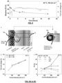
- the protons and carbonate/bicarbonate ions combine somewhere in the stationary catholyte layer, forming a virtual boundary where CO 2 is regenerated and diffuses towards Cu and CEL driven by the concentration gradient.
- the distances from this boundary to the Cu and CEL are noted as L 1 and L 2 , respectively.
- the zones between the boundary and Cu/CEL are noted as Zone 1 and Zone 2 for convenient discussion.
- the CO 2 concentration is zero everywhere in the stationary catholyte layer.
- Zone 1 After the electrolysis starts and proceeds, the CO 2 concentration at the boundary gradually arises, driving the generated CO 2 (dissolved form) to diffuse towards Cu and CEL.
- the CO 2 (dissolved form) that diffuses deeper into the stationary catholyte layer towards the CEL is not consumed by CO 2 RR but accumulates in Zone 2 until reaching a concentration close to that at the boundary (then no driving force).
- the CO 2 diffuses towards Cu is consumed for CO 2 RR, forming a concentration gradient in Zone 1, which creates a continuous CO 2 diffusion flux from boundary to Cu.
- Zone 1 can be described as a diffusion layer (see reference 40).
- the diffusion layer thickness, L 1 has great impacts on the CO 2 mass transport (see reference 40). Since the electric field of the stationary catholyte layer can be considered homogeneous (see reference 41), L 1 and L 2 are known to be proportional to the mobility of the corresponding ions. Given that L 1 + L 2 is the total thickness of the stationary catholyte layer, a thinner stationary catholyte layer has a thinner CO 2 diffusion layer ( L 1 ), which is beneficial for CO 2 mass transport from bulk to catalyst (see reference 40). In the future, thinner, yet mechanically robust porous layers, can be employed to improve the mass transport of the regenerated CO 2 , as discussed in SI2.
- the K 2 SO 4 catholyte in the stationary catholyte layer will gradually be partially transformed to KHCO 3 over time owing to reactions [1] and [2] as well as the slow leakage of SO 4 2- to anolyte.
- the CO 2 RR performance of SC-MEA was measured when a 1 M KHCO 3 buffer electrolyte is used as catholyte at the beginning. It was found that using 1 M KHCO 3 , the SC-MEA shows an expectable C 2 H 4 FE of ca. 23% at the current density of 100 mA cm -2 . However, its stability is poor in that the FE gradually decreases by > 50% after the initial 5 hours.
- HCO 3 - has a higher buffer capacity than SO 4 2- , and the pH gradient built up in KHCO 3 is thus expected to be smaller than that in K 2 SO 4 .
- the CO 2 diffusion layer thickness in KHCO 3 is thus likely greater than that in 0.5 M K 2 SO 4 catholyte (analyzed above).
- the regenerated CO 2 may gradually accumulate at the boundary ( Figure 6 ) because the concentration gradient-driven CO 2 diffusion flux is lower than the CO 2 generation rate.
- the accumulated aq. CO 2 reaches the saturated concentration, it could bubble out periodically and physically damage the catalyst layer and/or stationary catholyte layer. This phenomenon may also be the reason for the periodical voltage fluctuation in Figure 8 .
- the stationary catholyte layer was engineered in SC-MEA to a 125 ⁇ m thick, 0.5 M non-buffer K 2 SO 4 solution.
- the anode gas CO 2 contents were below the detection limit of the GC for the current density in the range between 100 to 300 mA cm -2 . This observation should be ascribed to the lower pH near the stationary catholyte layer/CEM interface, as shown in Figure 9A .
- Fumasep shows similar product distributions and a slightly better CO 2 crossover inhibiting capability ( Figures 2D , and 16 ) but higher cell voltage comparing with the one based on customized BPM, which is expectable. Therefore, the customized BPM was adopted in the neutral anolyte studies.
- the present invention founds that the composition and thickness of the catholyte layer influence the local pH, the efficiency of CO 2 regeneration and, thereby, the overall cell performance.
- a one-dimensional multiphysics model in COMSOL ® was applied to investigate the catholyte layer in BPM-based CO 2 RR electrolyzers.
- the CO 2 reactant is provided by two sources: the inlet CO 2 flow (gas) and the regenerated CO 2 (dissolved form, aq.) in the catholyte.
- the inlet CO 2 flow gas
- the regenerated CO 2 dissolved form, aq.
- the cathode CO 2 supply relies more on regeneration: in an ideal case with 100% SPU and 100% C 2+ selectivity, regeneration contributes 75% of the consumed CO 2 .
- the mass transport of regenerated CO 2 is most critical, and that transport is governed by catholyte composition and thickness.
- electrolysis creates a pH gradient through the catholyte layer: the pH is high near the cathode and low near the CEL.
- the protons and (bi)carbonate ions recombine in the catholyte, forming CO 2 (aq.) that diffuses, in response to a concentration gradient, to the Cu catalyst.
- Simulations resolve the local cathode environment as a function of dimensions, electrolyte and running conditions.
- the modeled thicknesses of 250, 125, 65 and 16 ⁇ m were selected to correspond to commercially available materials.
- a buffering catholyte e.g. KHCO 3
- a thick CO 2 (aq.) diffusion layer close to the catholyte thickness, since the CO 2 (aq.) is generated near the CEL surface. This effect reduces the CO 2 (aq.) mass-transfer efficiency.
- the local pH values near the cathode are greater than 11, which is sufficient to promote selectivity towards CO 2 RR over HER.
- Reducing the SC-layer thickness to 16 ⁇ m results in a cathode pH of 8.7, implying a lower selectivity toward CO 2 RR.
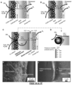
- Fig. 1c and 1d show the simulated concentration profiles of CO 2 (aq.) in the non-buffering SC-layer.
- the CO 2 (aq.) is continuously supplied to the cathode to participate in CO 2 RR, forming a concentration gradient (the boundary was defined here as the position where CO 2 concentration is 1% lower than the saturated concentration) to the cathode surface.
- Prior studies have termed the zone between the cathode and this boundary the diffusion layer (see reference 40).
- the thickness of the diffusion layer controls the efficiency of CO 2 (aq.) mass transport (see reference 40).
- the thicknesses of the diffusion layers are 75, 35, 12 and 5 ⁇ m for the catholyte layers with the thicknesses of 250, 125, 65 and 16 ⁇ m, respectively.
- the CO 2 (aq.) diffusion layer thickness in H-cells is typically 40-100 ⁇ m, and this does not support current densities exceeding 100 mA cm -2 . It was expected that diffusion layers ⁇ 40 ⁇ m, and a corresponding catholyte thickness ⁇ 150 ⁇ m, are required for sufficient mass transport in a non-buffering catholyte.
- the total thickness could not exceed 12 ⁇ m, and the cathodic pH would not be sufficiently alkaline for selective CO 2 RR.
- the simulation results suggest the following design principles for the catholyte layer in a BPM-based electrolyzer: the local cathode pH and the diffusion layer thickness of the regenerated CO 2 increase as the catholyte thickness increases; the buffering capacity of the catholyte increases the diffusion layer thickness and reduces transport. Precise control of the thickness of a non-buffering catholyte should thus offer a route to high SPU, CO 2 RR selectivity and reaction rate.
- the cathode was prepared by spraying Cu nanoparticles onto a hydrophobic carbon gas-diffusion layer for CO 2 RR.
- the anode was IrO 2 supported on Ti felt for the oxygen evolution reaction (OER).
- OER oxygen evolution reaction
- a BPM under reverse bias was employed with the AEL contacting the anode and the CEL contacting the SC-layer (porous support saturated with electrolyte).
- the cathode was compressed onto the porous layer, and the anode and cathode flow-field plates sandwiched the system.
- the anode CO 2 /O 2 ratio decreases as the operating current density increases, an effect that was ascribed to an increased flux of protons toward the cathode. This flux decreases the pH at the CEL surface and reduces the diffusion of CO 2 and HCO 3 - /CO 3 - in the CEL (see references 19 and 28).
- the thickness of the stationary catholyte was found to have a major impact on cell voltage.
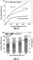
- the cell voltage of the SC-BPMEA decreases as the thickness of the SC-layer decreases ( Fig. 17 ) from 250 ⁇ m (5.1 V, 200 mA cm -2 ) to a minimum at 65 ⁇ m (3.8 V, 200 mA cm -2 ).
- Further thinning the catholyte to 16 ⁇ m resulted in higher voltage (4.4 V, 200 mA cm -2 ) - an effect of the lower-porosity support layer used in the 16 ⁇ m case ( ⁇ 20% vs. > 70% for the thicker layers).
- the simulations indicate that the thicker SC-layer results in longer transport distances for dissolved CO 2 .
- the CO 2 regeneration rate inside the SC-layer also depends on the current density, and for thicker SC-layers (e.g. > 125 ⁇ m), CO 2 bubbles are more prone to form near the CEL. These bubbles obstruct ion migration, increasing the ohmic resistance of the SC-BPMEA. Electrochemical impedance spectroscopy measurements also support this finding.
- the cell voltage of the SC-BPMEA with a 65 ⁇ m SC-layer operating at 200 mA cm -2 is 3.8 V, comparable to the AEM-based neutral-media MEAs operating at similar conditions (difference ⁇ ⁇ 0.05 V) (see references 5, 6 and 15).
- This result demonstrates that the cell voltage of a BPM-based CO 2 RR electrolyzer can be as low as that of an AEM-based electrolyzer with a current density of up to 200 mA cm -2 , while suppressing unwanted crossover and providing high SPU.
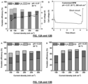
- the thickness of the SC-layer also affects selectivity towards CO 2 RR. With thicknesses of 65, 125 and 250 ⁇ m, the H 2 Faraday efficiencies (FEs) are consistent ( ⁇ 20% at 200 mA cm -2 , Fig. 19a-19c ), confirming that high local pH conditions are maintained the cathode in these cases. However, reducing the thickness to 16 ⁇ m increases the H 2 FE to 88% at 200 mA cm -2 ( Fig. 19d ), consistent with a cathodic pH that is reduced due to fast proton transport through a thin SC-layer. Without restricting CO 2 availability (the performance in Fig. 19a-19d was recorded at a CO 2 flow rate of 10 sccm cm -2 ), the SC-BPMEAs with the SC-layer thickness of 65, 125 and 250 ⁇ m show similar ethylene FE of 35-43%.
- the SC-BPMEA surpasses the SPU of conventional CO 2 -to-C 2+ electrolyzers, in which carbonate is the dominant charge carrier.
- Measuring the CO 2 SPUs with a restricted CO 2 flow rate is a direct approach to determining the upper bound of SPU in the CO 2 RR electrolyzers.
- the stationary catholyte thickness affects the SPU of the SC-BPMEA.
- the SPU gradually increases up to 21, 61 and 78% for the SC-BPMEAs with SC-layer thicknesses of 250, 125 and 65 ⁇ m, respectively ( Fig. 21 ).
- a thicker SC-layer produces a lower SPU ( Fig. 21 ).
- reactant CO 2 is available from the inlet gas stream and regeneration in the SC-layer.
- the H 2 FEs are similar for different stationary cathode layer thicknesses, indicating that both the CO 2 availability and local pH are unaffected by catholyte thickness under excess supply conditions.
- the simulations suggest that the thicker SC-layer results in a lower dissolved CO 2 flux to the cathode due to the smaller concentration gradient.
- CO 2 availability with thicker SC-layers decreases more significantly with reducing CO 2 flow rate, leading to a more dramatic increase in H 2 FE ( Fig. 22a-22c ).
- the experimental trends are generally consistent with those of the simulations.
- the SC-BPMEA with a dissolved CO 2 diffusion layer thicker than 75 ⁇ m fails to surpass the SPU limit because of insufficient mass transfer.
- a 65- ⁇ m SC-layer facilitates efficient mass transport of the regenerated CO 2 (diffusion layer thickness of 12 ⁇ m) and simultaneously promotes high local cathode pH.
- the SC-BPMEA shows > 50-h stability operating at 200 mA cm -2 with limited CO 2 availability (CO 2 input flow rate of 1.42 sccm cm -2 ). This operating stability is competitive with that of the neutral-electrolyte-based CO 2 -to-C 2+ electrolyzers.
- the inventors attempted to extend the SC-layer strategy in a CEM-based MEA cell (i.e. SC-CEMEA, Fig 9a ) using an acidic anolyte with pH ⁇ 2.4, expecting a lower cell voltage than the SC-BPMEA while maintaining high SPU. It was found that in the SC-CEMEA, the CO 2 crossover was essentially eliminated. This observation is ascribed to the lower pH near the stationary catholyte layer/CEM interface, as shown in Fig. 9a .
- SC-CEMEA shows a lower full cell voltage ( Fig. 9b ) compared to the SC-BPMEA presented, partly due to the lower resistance of the CEM and the absence of water dissociation overpotential. Meanwhile, it has a reasonable CO 2 RR selectivity over HER ( Fig. 9c ) due to the cation effect and high local pH induced by the presence K + in the SC-layer ( Fig. 9a ). However, this design is not amenable to steady-state operation without continuous addition of acid and salt to the anolyte, as the initial pH gradient will be eliminated due to co-ion transport and neutralization. We found the CO 2 RR selectivity decreases over time and approaches 100% H 2 after ⁇ 3 h.
- the protons also drag water molecules ( ⁇ 1 per proton) by electro-osmosis. It was accordingly calculated the water balance for different cathode products as listed in Table 2.
- the water generated and transported to the cathode appears to dilute and push out the electrolyte in the stationary catholyte layer, of which the volume is small (ca. 10 ⁇ L per cm 2 electrode area). This phenomenon results in flooding of the cathode (as confirmed experimentally) and loss of supporting electrolyte, thus degrading performance.
- the BPM slows co-ion transit across the membrane, compared to the CEM, by the large outward flux of OH - and H + from the water dissociating junction. Table 2.
- the energy costs (measured in gigajoules per tonne of the target product, GJ/t) for a CO 2 -to-C 2+ electrolyzer include the electrolysis electrical energy, cathodic stream separation, and anodic stream separation.
- CO 2 RR performance metrics of importance include cell voltage, target product FE, SPU and CO 2 crossover (see reference 12). High SPU and high energy efficiency have not been accomplished simultaneously in C 2+ electroproduction. In SC-BPMEAs, a higher SPU reduces the energy required for cathode separation, but the accompanying decrease in the ethylene selectivity ( Fig. 22c ) elevates the specific energy requirement.
- the energy intensity of producing ethylene in SC-BPMEA is ⁇ 30% lower than that in conventional neutral-electrolyte-based CO 2 electrolyzers (Table 3).
- conventional neutral-electrolyte CO 2 -to-ethylene electrolyzers the CO 2 crossover (at least 70%) costs 60-90 GJ per ton of ethylene to recover CO 2 from the anodic O 2 streams.
- this energy penalty cannot readily be reduced, independent of optimizing catalysts and operating conditions (e.g. input CO 2 flow rates, reaction rates, operating temperature and pressure).
- crossover CO 2 in SC-BPMEA is ⁇ 0.5% of the total CO 2 input, minimizing the energy cost of anodic separation.
- SC-BPMEA shows a cell voltage of 3.8 V at 200 mA cm -2 with an ethylene FE of 42% - voltages and selectivities comparable to the best conventional neutral-electrolyte CO 2 -to-ethylene MEAs (see reference 15).
- the energy intensity of the SC-BPMEA is 36% and 12% lower than acidic flow cell and acidic MEA, respectively (Table 3).
- the inventors have demonstrated a BPM-based CO 2 -to-C 2+ MEA, with a judiciously-designed SC-layer between catalyst and BPM, that overcomes the (bi)carbonate-formation reactant loss issue without compromising performance.
- the composition and thickness of the SC-layer determine the CO 2 RR performance and SPU via a strong influence on the local pH and the chemistry and transport of CO 2 .
- the buffering capacity and the thickness of the SC-layer determine the efficiency of the regeneration, the transport, and the availability of reactant CO 2 .
- the performance of the SC-BPMEA might be further improved using, for example, ionic liquid or other organic salts as the catholyte, and by optimizing the porosity, structure and hydrophobicity of the porous support layers.
- the CO 2 RR performance of the SC-BPMEA might be improved with new cathodic catalysts, optimizing the loading and processing of the catalyst layer, and by implementing BPMs with further-lowered water-dissociation voltage loss.
- the SC-BPMEA is a useful platform for evaluating CO 2 RR catalysts operating with high CO 2 utilization.
- Phosphoric acid H 3 PO 4 , 85%
- potassium sulfate K 2 SO 4 , 99%
- potassium bicarbonate KHCO 3 , 99.7%
- potassium chloride KCI, 99%
- potassium hydroxide KOH, 99.95%)
- copper nanoparticles 25 nm
- Nafion TM 1100W 5 wt. % in a mixture of lower aliphatic alcohols and water
- isopropanol IPA, 99%
- porous supports were also purchased from Fisher Scientific: 125 ⁇ m PVDF (0.45 ⁇ m pore size), 65 ⁇ m PTFE (0.44 ⁇ m pore size) and 16 ⁇ m PC (0.4 ⁇ m pore size).
- Nafion TM 212, Nafion TM XL, Fumasep (FAS-PET-130) and titanium (Ti) felt were purchased from Fuel Cell Store.
- Iridium(IV) chloride hydrate (Premion ® , 99.99%, metals basis, Ir 73% min) was purchased from Alfa Aesar. The water used in this study was 18 M ⁇ Milli-Q deionized- (DI-) water.
- Nafion membranes were activated through the following procedure: 1 h in 80 °C 1M H 2 SO 4 - 1 h in 80°C H 2 O 2 - 1 h in 1 M H 2 SO 4 - stored in DI-water. Fumasep was used as received and stored in 1 M KCI. Piperion (40 ⁇ m) was purchased from W7Energy and stored in 0.5 M KOH.
- the water dissociation catalyst layer was fabricated following a similar procedure in a previous report 17 .
- TiO 2 nanoparticles inks were prepared by sonicating the mixture of TiO 2 , DI-water, and IPA with the weight ratio of 1: 833: 2833 for 30 min.
- TiO 2 nanoparticle ink was spray-coated onto a Nafion 212 membrane, of which the edges were sealed by Kapton tape.
- the exposed membrane dimension was 2.2 cm ⁇ 2.2 cm.
- the nominal loading of TiO 2 is 0.2 mg cm -2 .
- the TiO 2 -coated Nafion TM was immediately used for assembling electrolyzers once prepared.
- the gas diffusion electrodes For the CO 2 RR, we prepared the gas diffusion electrodes (GDEs) by spray-depositing a catalyst ink dispersing 1 mg mL -1 of Cu nanoparticles and 0.25 mg mL -1 of Nafion TM 1100W in methanol onto a hydrophobic carbon paper. The mass loading of Cu NPs in the GDE was kept at 1.5 mg/cm 2 . The GDEs were dried in the air overnight prior to experiments.
- the OER electrode preparation procedure involves: etching the Ti felt in hydrochloric acid at 70 °C for 40 min; rinsing the etched Ti felt with DI water; immersing the Ti felt into an Ir(IV) chloride hydrate solution; drying and sintering the Ir-loaded Ti felt. The loading, drying, and sintering steps were repeated until a final Ir loading of 1.5 mg cm -2 was achieved.
- the MEA set (5 cm 2 ) was purchased from Dioxide Materials.
- a cathode was cut into a 2.1 cm ⁇ 2.1 cm piece and placed onto the MEA cathode plate with a flow window with a dimension of 2.2 cm ⁇ 2.2 cm.
- the four edges of the cathode were sealed by Kapton tape, which also made the flow window fully covered.
- the exposed cathode area was measured every time before the electrochemical tests, in the range of 3.1 to 4.2 cm 2 .
- a porous support layer (2 cm ⁇ 2 cm with various thicknesses, 250 ⁇ m was stacking two 125 ⁇ m-thick PVDF) saturated with desirable electrolyte (sonicated in electrolyte for 15 min to degas) was carefully placed.
- This porous support layer serves as the 'stationary catholyte layer (SC-layer).
- SC-layer The considerations of membrane selection can be found in SI2 and SI4 of the Supplementary Information.
- a TiO 2 -coated Nafion membrane was placed onto the SC-layer with the TiO 2 layer facing up, then covered by a Piperion (5 cm ⁇ 5 cm) membrane.
- the membrane When using Fumasep BPM, the membrane was placed with its cation-exchange layer (CEL) facing the cathode side.
- the CO 2 RR gas products, oxygen, and CO 2 were analyzed by injecting the gas samples into a gas chromatograph (Perkin Elmer Clarus 590) coupled with a thermal conductivity detector (TCD) and a flame ionization detector (FID).
- the gas chromatograph was equipped with a Molecular Sieve 5A Capillary Column and a packed Carboxen-1000 Column with argon as the carrier gas.
- the volumetric gas flow rates in and out of the cell were measured with a bubble column.
- x i is the volume fraction of the gas product i
- V is the outlet gas flow rate in L s -1
- P is atmosphere pressure 101.325 kPa
- R is the ideal gas constant 8.314 J mol -1 K -1
- T is the room temperature in K
- n i is the number of electrons required to produce one molecule of product
- F is the Faraday Constant 96485 C mol -1
- J is the total current in A.
- the liquid products from the cathode side of the SC-BPMEA were collected using a cold trap cooled to 0 °C.
- the collected liquid was combined with anolyte (some crossover liquid product) for quantifying by the proton nuclear magnetic resonance spectroscopy ( 1 H NMR) on an Agilent DD2 500 spectrometer in D 2 O using water suppression mode and dimethyl sulfoxide (DMSO) as the internal standard.
- 1 H NMR proton nuclear magnetic resonance spectroscopy
- Agilent DD2 500 spectrometer spectrometer in D 2 O using water suppression mode and dimethyl sulfoxide (DMSO) as the internal standard.
- DMSO dimethyl sulfoxide
- m i is the quantity of the liquid product i in mole
- t is the duration of product collection (1800 seconds).
- the electrochemical reaction model was performed by COMSOL Multiphysics version 5.5. This simulation was built upon previous modeling work. The local pH and different species concentrations were simulated for different catholyte thicknesses (16 ⁇ m, 65 ⁇ m, 125 ⁇ m, and 250 ⁇ m). Two different catholytes (K 2 SO 4 and KHCO 3 ) were used in the simulation. All the chemical reactions between species were considered in this one-dimensional modeling. The simulation included a 50 ⁇ m thick gas diffusion layer (GDL), a 0.1 ⁇ m thick Cu cathode catalyst (CL), a catholyte region with various thicknesses indicated above, and a cation exchange layer (CEL) boundary.
- GDL gas diffusion layer
- CL Cu cathode catalyst
- CEL cation exchange layer
- Constant concentration (Dirichlet) boundary conditions were used. Specifically, a constant concentration 37.8 mM of CO 2 was assumed within the GDL layer, as this region is in direct contact with the input CO 2 flow and thus assumed to be at equilibrium with gas phase CO 2 over this region for the purposes of the simulation.
- the BPM was interpreted as a boundary with a constant species concentration (1 M H 3 O + at the CEL surface), because it was assumed to generate protons as the dominant ionic charge carrier at a constant rate under constant current density (200 mA cm -2 ).
- a user-controlled mesh is employed in the COMSOL simulation.
- Edge type of mesh is used for GDL, CL, catholytes, respectively.
- the mesh distribution is predefined with an interval of 500 nm for GDL and catholytes, and an interval of 5nm for CL.
- I i represents the partial current density for CO, CH 4 , C 2 H 4 , and C 2 H 5 OH occurred at the cathode catalyst layer, respectively.
- n i represents the number of electrons transferred per mole reactant.
- F represents faraday's constant.
- I total represents the total current density. The FEs for the specific product is determined by the experimental results.
- ⁇ represents the catalyst porosity value.
- L catalyst represents the cathode catalyst length.
- the porosity value of 0.6 was used for the cathode catalyst and the porosity value of 1 for the catholyte region.
- the species diffusion coefficients are listed below. Species Diffusion coefficients D i (10 -9 m 2 s -1 ) CO 2 1.91 H 2 O 2.57 K 2 SO 4 1.39 KHCO 3 1.20 K + 1.98 H + 9.31 OH - 5.26 HCO 3 - 1.185 CO 3 2- 0.923 SO 4 2- 1.07
Landscapes
- Chemical & Material Sciences (AREA)
- Organic Chemistry (AREA)
- Engineering & Computer Science (AREA)
- Chemical Kinetics & Catalysis (AREA)
- Electrochemistry (AREA)
- Materials Engineering (AREA)
- Metallurgy (AREA)
- Electrolytic Production Of Non-Metals, Compounds, Apparatuses Therefor (AREA)
- Catalysts (AREA)
- Analytical Chemistry (AREA)
- Automation & Control Theory (AREA)
Claims (15)
- Elektroreduktionssystem zur Umwandlung von Kohlenstoffoxiden, ausgewählt aus CO, CO2 oder einer beliebigen Mischung davon, in Mehrfachkohlenstoffprodukte (C2+), wobei das System umfasst:- eine Kathodenkammer, die einen Reaktanteneinlass zum Empfangen eines Stroms von CO, CO2 oder einer beliebigen Mischung davon aufweist und eine Kathode umfasst, wobei die Kathode eine Katalysatorschicht umfasst, die in Kontakt mit einer Katholytlösung steht:- eine Anodenkammer, wobei die Anodenkammer eine Anode umfasst und eine fließende Anolytlösung aufnimmt;- eine bipolare Membran, die zwischen der Kathodenkammer und der Anodenkammer positioniert ist, wobei die bipolare Membran umfasst:eine Kationenaustauscherschicht (CEL) in Kationenkommunikation mit der Katholytlösung, um Protonen in der Katholytlösung bereitzustellen;eine Anionenaustauscherschicht (AEL) in Anionenkommunikation mit der Anolytlösung, um Hydroxidionen an einer Oberfläche der Anode bereitzustellen; undeine Grenzflächenschicht, die zwischen der Kationenaustauscherschicht und der Anionenaustauscherschicht zum Aufspalten von Wasser in die Protonen und die Hydroxidionen definiert ist;wobei die Kathodenkammer und/oder die Anodenkammer einen Produktauslass aufweisen, um die C2+-Produkte freizusetzen;dadurch gekennzeichnet, dass die Kathodenkammer eine stationäre Katholytschicht zwischen der Katalysatorschicht der Kathode und der CEL aufnimmt, wobei die stationäre Katholytschicht die Katholytlösung umfasst; dass die Dicke der stationären Katholytschicht höchstens 280 µm beträgt, gemessen mit einem Spiralmikrometer; und dass die Katholytlösung eine ungepufferte Lösung ist.
- System nach Anspruch 1, dadurch gekennzeichnet, dass die Dicke der stationären Katholytschicht zwischen 20 µm und 250 µm, gemessen mit einem Spiralmikrometer, liegt; bevorzugt zwischen 40 µm und 200 µm, bevorzugter zwischen 50 µm und 150 µm.
- System nach Anspruch 1 oder 2, dadurch gekennzeichnet, dass die Kathodenkammer ferner einen festen porösen Träger zwischen der CEL und der Katalysatorschicht umfasst und dass der feste poröse Träger mit der Katholytlösung gesättigt ist, um die stationäre Katholytschicht zu bilden; wobei vorzugsweise- der feste poröse Träger Polyvinylidenfluorid (PVDF), Polytetrafluorethylen (PTFE), Polycarbonat, Nylon, Celluloseacetat, Cellulosenitrat, Polypropylen, Aluminiumoxid oder beliebige Kombinationen davon umfasst; und/oder- der feste poröse Träger einen mittleren Porendurchmesser zwischen 0,05 und 50 µm aufweist, bestimmt durch Rasterelektronenmikroskopie; und/oder- die stationäre Katholytschicht einen Flüssigkeitsgehalt zwischen 5 und 50 µl.cm-2 aufweist, wenn der feste poröse Träger mit der Katholytlösung gesättigt ist; wobei der Flüssigkeitsgehalt durch Wiegen bestimmt wird; und/oder- der feste poröse Träger für einen direkten Kontakt damit zwischen der Katalysatorschicht der Kathode und der CEL eingeklemmt ist.
- System nach einem der Ansprüche 1 bis 3, dadurch gekennzeichnet, dass die Katholytlösung eine Kationenkonzentration zwischen 0,25 M und 3 M aufweist; wobei die Katholytlösung vorzugsweise eine Lösung von K2SO4 mit einer K+-Konzentration von gleich oder größer als 0,5 M ist.
- System nach einem der Ansprüche 1 bis 4, dadurch gekennzeichnet, dass die Kationen in der Katholytlösung eines oder mehrere sind, ausgewählt aus K+, Na+, Cs+, Rb+, NH4+, Mg2+, Ca2+, Al3+; wobei die Katholytlösung vorzugsweise eine Lösung mit einer Kationen-Konzentration von gleich oder größer als 0,5 M ist.
- System nach einem der Ansprüche 1 bis 5, dadurch gekennzeichnet, dass die ungepufferte Lösung K2SO4, KCI oder beliebige andere Kombinationen der Cl--Anionen oder SO4 2--Anionen mit Na+-, Cs+-, Rb+-, NH4+-, Mg2+-, Ca2+- oder Al3+-Kationen ist oder umfasst.
- System nach einem der Ansprüche 1 bis 6, dadurch gekennzeichnet, dass die Anolytlösung einen pH-Wert zwischen 7 und 10 aufweist; wobei die Anolytlösung vorzugsweise eine KHCO3-, K2SO4- oder K2HPO4-Lösung ist.
- System nach einem der Ansprüche 1 bis 7, dadurch gekennzeichnet, dass die Anolytlösung eine saure Lösung ist und einen pH-Wert zwischen 1 und 4 aufweist; wobei die saure Lösung vorzugsweise eine H3PO4-Lösung, H2SO4-Lösung oder eine Kombination davon ist.
- System nach einem der Ansprüche 1 bis 8, dadurch gekennzeichnet, dass:- die Anolytlösung eine Anolytkonzentration zwischen 2,0 M und 0,01 M aufweist; und/oder- die Katalysatorschicht der Kathode Kupfer (Cu), Silber (Ag), Platin (Pt), Kohlenstoff (C) oder eine beliebige Kombination davon umfasst; und/oder- die Kathode ferner eine Gasdiffusionsschicht zum Kontaktieren des Stroms von CO, CO2 oder einer beliebigen Mischung davon umfasst und sich die Katalysatorschicht auf der Gasdiffusionsschicht abgelagert hat; und/oder- das System ferner eine Temperatursteuerung umfasst, die so konfiguriert ist, dass sie eine Betriebstemperatur zwischen 20 °C und 50 °C aufrechterhält.
- System nach einem der Ansprüche 1 bis 9, dadurch gekennzeichnet, dass die Anode eine anodische Katalysatorschicht und eine anodische Stromkollektorschicht umfasst; wobei die anodische Katalysatorschicht vorzugsweise eine oder mehrere ausgewählt aus IrO2, Pt, Pd, Ni, NiOx, CoOx umfasst.
- System nach einem der Ansprüche 1 bis 10, dadurch gekennzeichnet, dass die Grenzflächenschicht der bipolaren Membran einen Wasserdissoziationskatalysator umfasst; wobei der Wasserdissoziationskatalysator vorzugsweise als Nanopartikel vorhanden ist und/oder der Wasserdissoziationskatalysator einen oder mehrere ausgewählt aus TiO2, IrO2, NiO, SnO2, Graphenoxid, CoOx, ZrO2, Al2O3, Fe(OH)3, MnO2, Ru, Rh, RuPt-Legierung, Ptlr-Legierung, Ir, Pt umfasst.
- System nach einem der Ansprüche 1 bis 11, dadurch gekennzeichnet, dass die AEL eine Membran ist, die Poly(arylpiperidinium), Polystyrolmethylmethylimidazolium oder Polystyroltetramethylmethylimidazolium umfasst; und/oder dadurch, dass die CEL ein sulfoniertes Fluorpolymer-Copolymer auf Tetrafluorethylenbasis umfasst oder daraus besteht.
- Kohlenstoffoxid-Elektroreduktionsverfahren zur Umwandlung von CO, CO2 oder einer beliebigen Mischung davon in C2+-Produkte, wobei das Verfahren umfasst:
Zuführen einer Katholytlösung und eines Stroms von CO, CO2 oder einer beliebigen Mischung davon zu einer Kathodenkammer, die eine Katalysatorschicht in Kontakt mit der Katholytlösung umfasst; und einen Produktauslass aufweist, um die C2+-Produkte freizusetzen:Fließenlassen einer Anolytlösung durch eine Anodenkammer, wobei die Anodenkammer eine Anode umfasst;Bereitstellen einer bipolaren Membran zwischen der Kathodenkammer und der Anodenkammer, wobei die bipolare Membran umfasst:eine Kationenaustauscherschicht (CEL) in Kationenkommunikation mit der Katholytlösung, um Protonen in der Katholytlösung bereitzustellen;eine Anionenaustauscherschicht (AEL) in Anionenkommunikation mit der Anolytlösung, um Hydroxidionen in der Anolytlösung bereitzustellen; undeine Grenzflächenschicht, die zwischen der Kationenaustauscherschicht und der Anionenaustauscherschicht zum Aufspalten von Wasser in die Protonen und die Hydroxidionen definiert ist; undZurückhalten eines Abschnitts der Katholytlösung als stationäre Katholytschicht zwischen der Katalysatorschicht der Kathode und der CEL und in Kontakt mit der CEL, wobei die Dicke der stationären Katholytschicht höchstens 280 µm beträgt, gemessen mit einem Spiralmikrometer, und wobei die Katholytlösung eine ungepufferte Lösung ist. - Verfahren nach Anspruch 13, dadurch gekennzeichnet, dass es umfasst:- Aufrechterhalten einer Betriebstemperatur zwischen 20 °C und 50 °C; und/oder- Zuführen des Stroms von CO, CO2 oder einer beliebigen Mischung davon zu der Kathodenkammer mit einer Einlassdurchflussrate zwischen 1 sccm und 15 sccm; und/oder- Bereitstellen einer angelegten Stromdichte zwischen 100 und 400 mA.cm-2 für die Kathode; und/oder- Versorgen der Katholytlösung mit einer Kationenkonzentration zwischen 0,25 M und 3 M; und/oder- Bilden der stationären Katholytschicht mit einer Dicke zwischen 20 µm und 250 µm, gemessen mit einem Spiralmikrometer.
- Verfahren nach einem der Ansprüche 13 oder 14, dadurch gekennzeichnet, dass es das Bilden der stationären Katholytschicht durch Bereitstellen eines festen porösen Trägers zwischen der Kathode und der CEL und das Sättigen des festen porösen Trägers mit der Katholytlösung umfasst; wobei das Sättigen vorzugsweise so durchgeführt wird, dass ein Flüssigkeitsgehalt der stationären Katholytschicht zwischen 5 und 50 µl.cm-2 erreicht wird, wenn der feste poröse Träger mit der Katholytlösung gesättigt ist; wobei der Flüssigkeitsgehalt durch Wiegen bestimmt wird.
Applications Claiming Priority (2)
| Application Number | Priority Date | Filing Date | Title |
|---|---|---|---|
| US202163210675P | 2021-06-15 | 2021-06-15 | |
| PCT/EP2022/065823 WO2022263316A1 (en) | 2021-06-15 | 2022-06-10 | System for electrocatalytic conversion of carbon oxides to multicarbon products using a stationary catholyte layer and related process |
Publications (2)
| Publication Number | Publication Date |
|---|---|
| EP4355932A1 EP4355932A1 (de) | 2024-04-24 |
| EP4355932B1 true EP4355932B1 (de) | 2025-03-26 |
Family
ID=82321491
Family Applications (1)
| Application Number | Title | Priority Date | Filing Date |
|---|---|---|---|
| EP22735366.1A Active EP4355932B1 (de) | 2021-06-15 | 2022-06-10 | System zur elektrokatalytischen umwandlung von kohlenstoffoxiden in mehrkohlenstoffprodukte unter verwendung einer stationären katholytschicht und zugehöriges verfahren |
Country Status (8)
| Country | Link |
|---|---|
| US (1) | US20240271294A1 (de) |
| EP (1) | EP4355932B1 (de) |
| CA (1) | CA3219519A1 (de) |
| DK (1) | DK4355932T3 (de) |
| ES (1) | ES3025035T3 (de) |
| FI (1) | FI4355932T3 (de) |
| PT (1) | PT4355932T (de) |
| WO (1) | WO2022263316A1 (de) |
Families Citing this family (7)
| Publication number | Priority date | Publication date | Assignee | Title |
|---|---|---|---|---|
| JP7145264B1 (ja) * | 2021-03-23 | 2022-09-30 | 本田技研工業株式会社 | 二酸化炭素処理装置、二酸化炭素処理方法及び炭素化合物の製造方法 |
| US20240200207A1 (en) * | 2022-12-19 | 2024-06-20 | Dioxycle | Catalyst Revitalization for Oxocarbon Electrolyzer |
| WO2024234105A1 (en) * | 2023-05-17 | 2024-11-21 | The Governing Council Of The University Of Toronto | Electroreduction of carbonate to multicarbon products using an mea with an interposer |
| EP4512934A1 (de) * | 2023-08-22 | 2025-02-26 | Siemens Energy Global GmbH & Co. KG | Neuartiges design einer membranelektrodenanordnung für c2h4-selektive cem-co2-elektrolyseure |
| WO2025106968A1 (en) * | 2023-11-17 | 2025-05-22 | The Penn State Research Foundation | Selective recovery of li from brine solutions & coversion to lioh in a single electrochemical cell |
| WO2025227049A1 (en) * | 2024-04-26 | 2025-10-30 | Northwestern University | Systems and methods for energy-efficient electrified ethylene production from carbonate capture liquid |
| CN119633600B (zh) * | 2024-12-09 | 2026-04-03 | 中国科学技术大学 | 一种基于荷电纳米片催化层的双极膜及其制备方法和在海水解离中的应用 |
Family Cites Families (2)
| Publication number | Priority date | Publication date | Assignee | Title |
|---|---|---|---|---|
| WO2019051609A1 (en) * | 2017-09-14 | 2019-03-21 | The University Of British Columbia | SYSTEMS AND METHODS FOR ELECTROCHEMICAL REDUCTION OF CARBON DIOXIDE |
| CA3098176A1 (en) * | 2018-04-25 | 2019-10-31 | The University Of British Columbia | Systems and methods for electrochemical generation of syngas and other useful chemicals |
-
2022
- 2022-06-10 WO PCT/EP2022/065823 patent/WO2022263316A1/en not_active Ceased
- 2022-06-10 FI FIEP22735366.1T patent/FI4355932T3/fi active
- 2022-06-10 DK DK22735366.1T patent/DK4355932T3/da active
- 2022-06-10 PT PT227353661T patent/PT4355932T/pt unknown
- 2022-06-10 US US18/567,238 patent/US20240271294A1/en active Pending
- 2022-06-10 CA CA3219519A patent/CA3219519A1/en active Pending
- 2022-06-10 ES ES22735366T patent/ES3025035T3/es active Active
- 2022-06-10 EP EP22735366.1A patent/EP4355932B1/de active Active
Also Published As
| Publication number | Publication date |
|---|---|
| WO2022263316A1 (en) | 2022-12-22 |
| PT4355932T (pt) | 2025-05-14 |
| US20240271294A1 (en) | 2024-08-15 |
| ES3025035T3 (en) | 2025-06-05 |
| FI4355932T3 (fi) | 2025-06-03 |
| EP4355932A1 (de) | 2024-04-24 |
| DK4355932T3 (da) | 2025-05-26 |
| CA3219519A1 (en) | 2022-12-22 |
Similar Documents
| Publication | Publication Date | Title |
|---|---|---|
| EP4355932B1 (de) | System zur elektrokatalytischen umwandlung von kohlenstoffoxiden in mehrkohlenstoffprodukte unter verwendung einer stationären katholytschicht und zugehöriges verfahren | |
| Zhang et al. | Porous metal electrodes enable efficient electrolysis of carbon capture solutions | |
| Gawel et al. | Electrochemical CO2 reduction-The macroscopic world of electrode design, reactor concepts & economic aspects | |
| Park et al. | Strategies for CO2 electroreduction in cation exchange membrane electrode assembly | |
| Guzmán et al. | CO 2 valorisation towards alcohols by Cu-based electrocatalysts: challenges and perspectives | |
| Disch et al. | Strategies for the mitigation of salt precipitation in zero-gap CO 2 electrolyzers producing CO | |
| EP3623501B1 (de) | Kohlendioxidelektrolysevorrichtung | |
| US20250084542A1 (en) | Use of a porous recycling layer for co2 electroreduction to multicarbon products with high conversion efficiency | |
| KR20210131999A (ko) | 전해기 및 사용 방법 | |
| Pribyl-Kranewitter et al. | Investigation and optimisation of operating conditions for low-temperature CO2 reduction to CO in a forward-bias bipolar-membrane electrolyser | |
| US20250019844A1 (en) | Co2 electroreduction to multi-carbon products in strong acid | |
| Kuo et al. | Toward efficient catalysts for electrochemical CO2 conversion to C2 products | |
| JP2023042896A (ja) | 二酸化炭素電解装置 | |
| US11667592B2 (en) | Methods and apparatus for performing chemical and electrochemical reactions | |
| Haspel et al. | Is hydroxide just hydroxide? Unidentical CO2 hydration conditions during hydrogen evolution and carbon dioxide reduction in zero-gap gas diffusion electrode reactors | |
| Hintjens et al. | Unravelling the key role of ion-exchange membranes in water management and ion crossover for zero-gap CO 2 electrolyzers | |
| US20230151501A1 (en) | Electrolytic conversion of carbon-containing ions using porous metal electrodes | |
| Zhou et al. | Advances in CO2 electroreduction to ethylene over Cu-based catalysts in membrane electrode assembly | |
| Zhang et al. | Metallic porous electrodes enable efficient bicarbonate electrolysis | |
| Dominguez et al. | Reliable and Efficient Electrochemical Recovery of O2 from Metabolic CO2 at the International Space Station (ISS) | |
| Park et al. | Towards the Large-Scale Electrochemical Reduction of Carbon Dioxide. Catalysts 2021, 11, 253 | |
| US20260043152A1 (en) | Method for preventing salt precipitation in a zero-gap co2 reduction electrolyzer | |
| NL2034513B1 (en) | Stable operation of a CO2 electrolyser via a pre-conditioning process | |
| US20240295035A1 (en) | Electrolytic cell for polymer electrolyte membrane electrolysis and method for production thereof | |
| Kato et al. | Suppression of Salt Precipitation in Membrane Electrode Assembly Electrolyzers for CO2 reduction reactions by Intermittent Supply of Alkali Metal Cations |
Legal Events
| Date | Code | Title | Description |
|---|---|---|---|
| STAA | Information on the status of an ep patent application or granted ep patent |
Free format text: STATUS: UNKNOWN |
|
| STAA | Information on the status of an ep patent application or granted ep patent |
Free format text: STATUS: THE INTERNATIONAL PUBLICATION HAS BEEN MADE |
|
| PUAI | Public reference made under article 153(3) epc to a published international application that has entered the european phase |
Free format text: ORIGINAL CODE: 0009012 |
|
| STAA | Information on the status of an ep patent application or granted ep patent |
Free format text: STATUS: REQUEST FOR EXAMINATION WAS MADE |
|
| 17P | Request for examination filed |
Effective date: 20240102 |
|
| AK | Designated contracting states |
Kind code of ref document: A1 Designated state(s): AL AT BE BG CH CY CZ DE DK EE ES FI FR GB GR HR HU IE IS IT LI LT LU LV MC MK MT NL NO PL PT RO RS SE SI SK SM TR |
|
| DAV | Request for validation of the european patent (deleted) | ||
| DAX | Request for extension of the european patent (deleted) | ||
| GRAP | Despatch of communication of intention to grant a patent |
Free format text: ORIGINAL CODE: EPIDOSNIGR1 |
|
| STAA | Information on the status of an ep patent application or granted ep patent |
Free format text: STATUS: GRANT OF PATENT IS INTENDED |
|
| INTG | Intention to grant announced |
Effective date: 20241018 |
|
| GRAS | Grant fee paid |
Free format text: ORIGINAL CODE: EPIDOSNIGR3 |
|
| GRAA | (expected) grant |
Free format text: ORIGINAL CODE: 0009210 |
|
| STAA | Information on the status of an ep patent application or granted ep patent |
Free format text: STATUS: THE PATENT HAS BEEN GRANTED |
|
| P01 | Opt-out of the competence of the unified patent court (upc) registered |
Free format text: CASE NUMBER: APP_5870/2025 Effective date: 20250204 |
|
| AK | Designated contracting states |
Kind code of ref document: B1 Designated state(s): AL AT BE BG CH CY CZ DE DK EE ES FI FR GB GR HR HU IE IS IT LI LT LU LV MC MK MT NL NO PL PT RO RS SE SI SK SM TR |
|
| REG | Reference to a national code |
Ref country code: GB Ref legal event code: FG4D |
|
| REG | Reference to a national code |
Ref country code: CH Ref legal event code: EP |
|
| REG | Reference to a national code |
Ref country code: DE Ref legal event code: R096 Ref document number: 602022012318 Country of ref document: DE |
|
| REG | Reference to a national code |
Ref country code: IE Ref legal event code: FG4D |
|
| REG | Reference to a national code |
Ref country code: PT Ref legal event code: SC4A Ref document number: 4355932 Country of ref document: PT Date of ref document: 20250514 Kind code of ref document: T Free format text: AVAILABILITY OF NATIONAL TRANSLATION Effective date: 20250508 Ref country code: NL Ref legal event code: FP |
|
| REG | Reference to a national code |
Ref country code: DK Ref legal event code: T3 Effective date: 20250521 |
|
| REG | Reference to a national code |
Ref country code: FI Ref legal event code: FGE |
|
| REG | Reference to a national code |
Ref country code: ES Ref legal event code: FG2A Ref document number: 3025035 Country of ref document: ES Kind code of ref document: T3 Effective date: 20250605 |
|
| REG | Reference to a national code |
Ref country code: SE Ref legal event code: TRGR |
|
| PG25 | Lapsed in a contracting state [announced via postgrant information from national office to epo] |
Ref country code: RS Free format text: LAPSE BECAUSE OF FAILURE TO SUBMIT A TRANSLATION OF THE DESCRIPTION OR TO PAY THE FEE WITHIN THE PRESCRIBED TIME-LIMIT Effective date: 20250626 |
|
| PGFP | Annual fee paid to national office [announced via postgrant information from national office to epo] |
Ref country code: FI Payment date: 20250627 Year of fee payment: 4 |
|
| PGFP | Annual fee paid to national office [announced via postgrant information from national office to epo] |
Ref country code: DE Payment date: 20250618 Year of fee payment: 4 |
|
| PGFP | Annual fee paid to national office [announced via postgrant information from national office to epo] |
Ref country code: DK Payment date: 20250625 Year of fee payment: 4 |
|
| REG | Reference to a national code |
Ref country code: LT Ref legal event code: MG9D |
|
| PGFP | Annual fee paid to national office [announced via postgrant information from national office to epo] |
Ref country code: NO Payment date: 20250624 Year of fee payment: 4 |
|
| PGFP | Annual fee paid to national office [announced via postgrant information from national office to epo] |
Ref country code: NL Payment date: 20250618 Year of fee payment: 4 Ref country code: BE Payment date: 20250618 Year of fee payment: 4 |
|
| PG25 | Lapsed in a contracting state [announced via postgrant information from national office to epo] |
Ref country code: HR Free format text: LAPSE BECAUSE OF FAILURE TO SUBMIT A TRANSLATION OF THE DESCRIPTION OR TO PAY THE FEE WITHIN THE PRESCRIBED TIME-LIMIT Effective date: 20250326 |
|
| PG25 | Lapsed in a contracting state [announced via postgrant information from national office to epo] |
Ref country code: LV Free format text: LAPSE BECAUSE OF FAILURE TO SUBMIT A TRANSLATION OF THE DESCRIPTION OR TO PAY THE FEE WITHIN THE PRESCRIBED TIME-LIMIT Effective date: 20250326 |
|
| PGFP | Annual fee paid to national office [announced via postgrant information from national office to epo] |
Ref country code: PT Payment date: 20250529 Year of fee payment: 4 |
|
| PGFP | Annual fee paid to national office [announced via postgrant information from national office to epo] |
Ref country code: FR Payment date: 20250627 Year of fee payment: 4 |
|
| PG25 | Lapsed in a contracting state [announced via postgrant information from national office to epo] |
Ref country code: GR Free format text: LAPSE BECAUSE OF FAILURE TO SUBMIT A TRANSLATION OF THE DESCRIPTION OR TO PAY THE FEE WITHIN THE PRESCRIBED TIME-LIMIT Effective date: 20250627 Ref country code: BG Free format text: LAPSE BECAUSE OF FAILURE TO SUBMIT A TRANSLATION OF THE DESCRIPTION OR TO PAY THE FEE WITHIN THE PRESCRIBED TIME-LIMIT Effective date: 20250326 |
|
| PGFP | Annual fee paid to national office [announced via postgrant information from national office to epo] |
Ref country code: AT Payment date: 20250721 Year of fee payment: 4 |
|
| PGFP | Annual fee paid to national office [announced via postgrant information from national office to epo] |
Ref country code: SE Payment date: 20250618 Year of fee payment: 4 |
|
| REG | Reference to a national code |
Ref country code: AT Ref legal event code: MK05 Ref document number: 1779053 Country of ref document: AT Kind code of ref document: T Effective date: 20250326 |
|
| PG25 | Lapsed in a contracting state [announced via postgrant information from national office to epo] |
Ref country code: SM Free format text: LAPSE BECAUSE OF FAILURE TO SUBMIT A TRANSLATION OF THE DESCRIPTION OR TO PAY THE FEE WITHIN THE PRESCRIBED TIME-LIMIT Effective date: 20250326 |
|
| PGFP | Annual fee paid to national office [announced via postgrant information from national office to epo] |
Ref country code: ES Payment date: 20250731 Year of fee payment: 4 |
|
| PG25 | Lapsed in a contracting state [announced via postgrant information from national office to epo] |
Ref country code: IT Free format text: LAPSE BECAUSE OF FAILURE TO SUBMIT A TRANSLATION OF THE DESCRIPTION OR TO PAY THE FEE WITHIN THE PRESCRIBED TIME-LIMIT Effective date: 20250326 Ref country code: PL Free format text: LAPSE BECAUSE OF FAILURE TO SUBMIT A TRANSLATION OF THE DESCRIPTION OR TO PAY THE FEE WITHIN THE PRESCRIBED TIME-LIMIT Effective date: 20250326 |
|
| PG25 | Lapsed in a contracting state [announced via postgrant information from national office to epo] |
Ref country code: AT Free format text: LAPSE BECAUSE OF FAILURE TO SUBMIT A TRANSLATION OF THE DESCRIPTION OR TO PAY THE FEE WITHIN THE PRESCRIBED TIME-LIMIT Effective date: 20250326 |
|
| PG25 | Lapsed in a contracting state [announced via postgrant information from national office to epo] |
Ref country code: EE Free format text: LAPSE BECAUSE OF FAILURE TO SUBMIT A TRANSLATION OF THE DESCRIPTION OR TO PAY THE FEE WITHIN THE PRESCRIBED TIME-LIMIT Effective date: 20250326 |
|
| PG25 | Lapsed in a contracting state [announced via postgrant information from national office to epo] |
Ref country code: RO Free format text: LAPSE BECAUSE OF FAILURE TO SUBMIT A TRANSLATION OF THE DESCRIPTION OR TO PAY THE FEE WITHIN THE PRESCRIBED TIME-LIMIT Effective date: 20250326 |
|
| PG25 | Lapsed in a contracting state [announced via postgrant information from national office to epo] |
Ref country code: SK Free format text: LAPSE BECAUSE OF FAILURE TO SUBMIT A TRANSLATION OF THE DESCRIPTION OR TO PAY THE FEE WITHIN THE PRESCRIBED TIME-LIMIT Effective date: 20250326 |
|
| PG25 | Lapsed in a contracting state [announced via postgrant information from national office to epo] |
Ref country code: IS Free format text: LAPSE BECAUSE OF FAILURE TO SUBMIT A TRANSLATION OF THE DESCRIPTION OR TO PAY THE FEE WITHIN THE PRESCRIBED TIME-LIMIT Effective date: 20250726 |
|
| REG | Reference to a national code |
Ref country code: DE Ref legal event code: R097 Ref document number: 602022012318 Country of ref document: DE |
|
| PG25 | Lapsed in a contracting state [announced via postgrant information from national office to epo] |
Ref country code: CZ Free format text: LAPSE BECAUSE OF FAILURE TO SUBMIT A TRANSLATION OF THE DESCRIPTION OR TO PAY THE FEE WITHIN THE PRESCRIBED TIME-LIMIT Effective date: 20250326 |
|
| REG | Reference to a national code |
Ref country code: CH Ref legal event code: H13 Free format text: ST27 STATUS EVENT CODE: U-0-0-H10-H13 (AS PROVIDED BY THE NATIONAL OFFICE) Effective date: 20260127 |
|
| PG25 | Lapsed in a contracting state [announced via postgrant information from national office to epo] |
Ref country code: MC Free format text: LAPSE BECAUSE OF FAILURE TO SUBMIT A TRANSLATION OF THE DESCRIPTION OR TO PAY THE FEE WITHIN THE PRESCRIBED TIME-LIMIT Effective date: 20250326 |
|
| PLBE | No opposition filed within time limit |
Free format text: ORIGINAL CODE: 0009261 |
|
| STAA | Information on the status of an ep patent application or granted ep patent |
Free format text: STATUS: NO OPPOSITION FILED WITHIN TIME LIMIT |
|
| REG | Reference to a national code |
Ref country code: CH Ref legal event code: L10 Free format text: ST27 STATUS EVENT CODE: U-0-0-L10-L00 (AS PROVIDED BY THE NATIONAL OFFICE) Effective date: 20260211 |
|
| PG25 | Lapsed in a contracting state [announced via postgrant information from national office to epo] |
Ref country code: LU Free format text: LAPSE BECAUSE OF NON-PAYMENT OF DUE FEES Effective date: 20250610 |
|
| 26N | No opposition filed |
Effective date: 20260105 |
|
| PG25 | Lapsed in a contracting state [announced via postgrant information from national office to epo] |
Ref country code: IE Free format text: LAPSE BECAUSE OF NON-PAYMENT OF DUE FEES Effective date: 20250610 |
|
| PG25 | Lapsed in a contracting state [announced via postgrant information from national office to epo] |
Ref country code: CH Free format text: LAPSE BECAUSE OF NON-PAYMENT OF DUE FEES Effective date: 20250630 |