EP4355975B1 - Verdunkelungsvorrichtung - Google Patents
Verdunkelungsvorrichtung Download PDFInfo
- Publication number
- EP4355975B1 EP4355975B1 EP22734918.0A EP22734918A EP4355975B1 EP 4355975 B1 EP4355975 B1 EP 4355975B1 EP 22734918 A EP22734918 A EP 22734918A EP 4355975 B1 EP4355975 B1 EP 4355975B1
- Authority
- EP
- European Patent Office
- Prior art keywords
- electromechanical actuator
- configuration
- electrical connection
- maintenance terminal
- control unit
- Prior art date
- Legal status (The legal status is an assumption and is not a legal conclusion. Google has not performed a legal analysis and makes no representation as to the accuracy of the status listed.)
- Active
Links
Images


Classifications
-
- E—FIXED CONSTRUCTIONS
- E06—DOORS, WINDOWS, SHUTTERS, OR ROLLER BLINDS IN GENERAL; LADDERS
- E06B—FIXED OR MOVABLE CLOSURES FOR OPENINGS IN BUILDINGS, VEHICLES, FENCES OR LIKE ENCLOSURES IN GENERAL, e.g. DOORS, WINDOWS, BLINDS, GATES
- E06B9/00—Screening or protective devices for wall or similar openings, with or without operating or securing mechanisms; Closures of similar construction
- E06B9/24—Screens or other constructions affording protection against light, especially against sunshine; Similar screens for privacy or appearance; Slat blinds
- E06B9/26—Lamellar or like blinds, e.g. venetian blinds
- E06B9/28—Lamellar or like blinds, e.g. venetian blinds with horizontal lamellae, e.g. non-liftable
- E06B9/30—Lamellar or like blinds, e.g. venetian blinds with horizontal lamellae, e.g. non-liftable liftable
- E06B9/32—Operating, guiding, or securing devices therefor
- E06B9/322—Details of operating devices, e.g. pulleys, brakes, spring drums, drives
-
- E—FIXED CONSTRUCTIONS
- E06—DOORS, WINDOWS, SHUTTERS, OR ROLLER BLINDS IN GENERAL; LADDERS
- E06B—FIXED OR MOVABLE CLOSURES FOR OPENINGS IN BUILDINGS, VEHICLES, FENCES OR LIKE ENCLOSURES IN GENERAL, e.g. DOORS, WINDOWS, BLINDS, GATES
- E06B9/00—Screening or protective devices for wall or similar openings, with or without operating or securing mechanisms; Closures of similar construction
- E06B9/56—Operating, guiding or securing devices or arrangements for roll-type closures; Spring drums; Tape drums; Counterweighting arrangements therefor
- E06B9/68—Operating devices or mechanisms, e.g. with electric drive
- E06B2009/6809—Control
Definitions
- the present invention relates to a blackout device comprising at least one screen, a motorized drive device and a configuration or maintenance terminal.
- the present invention relates to the field of occultation devices comprising a motorized drive device moving a screen, between at least a first position and at least a second position.
- a motorized drive device comprises an electromechanical actuator of a movable sun protection or closing element, such as a blind, in particular a slatted blind, a shutter, a door, a grille, a curtain or any other equivalent material, hereinafter called a screen.
- a movable sun protection or closing element such as a blind, in particular a slatted blind, a shutter, a door, a grille, a curtain or any other equivalent material, hereinafter called a screen.
- This blackout device comprises a screen, a motorized drive device and a configuration or maintenance terminal.
- the motorized drive device comprises an electromechanical actuator and an electrical power cable.
- the electromechanical actuator is configured to move the screen.
- the electromechanical actuator is configured to be supplied with electrical energy from a main power source, via the electrical power cable.
- the electromechanical actuator comprises an electronic control unit, an electric motor, an output shaft and an electrical connection device.
- the electrical connection device is electrically connected to the electronic control unit.
- the configuration or maintenance terminal comprises an electronic unit, an electrical connection cable and an electrical socket.
- the electrical outlet is, on the one hand, configured to be electrically connected to the electrical connection device of the electromechanical actuator and, on the other hand, configured to be electrically connected to the electronic unit of the configuration or maintenance terminal, via the electrical connection cable.
- This concealment device is generally satisfactory.
- this occulting device has the disadvantage that, when the configuration or maintenance terminal is electrically connected to the electromechanical actuator, in particular to the electronic control unit of the electromechanical actuator, the electromechanical actuator must be supplied with electrical energy at from a primary power source, such as a mains power supply or a battery.
- a primary power source such as a mains power supply or a battery.
- the electronic control unit of the electromechanical actuator needs to be supplied with electrical energy from the main power source, via the power supply cable.
- the supply of electrical energy to the electromechanical actuator from the main electrical power source is cut off as soon as a command to the electric motor is completed.
- the electronic control unit of the electromechanical actuator is no longer supplied with electrical energy and it cannot implement a reset or adjustment of the operating parameters of the electromechanical actuator, a diagnosis of the operating data of the electromechanical actuator, or an update or replacement of software stored in a memory of the electronic control unit of the electromechanical actuator, from the configuration or maintenance terminal.
- the present invention aims to resolve the aforementioned drawbacks and to propose a concealment device making it possible to dispense with an electrical power supply to the electromechanical actuator from the main electrical power source when the configuration or maintenance terminal is electrically connected to the electromechanical actuator.
- the configuration or maintenance terminal when the configuration or maintenance terminal is electrically connected to the electromechanical actuator, at least by means of the electrical connection cable and the electrical socket of the configuration or maintenance terminal and the electrical connection device of the electromechanical actuator, the configuration or maintenance terminal supplies electrical energy to the electronic control unit of the electromechanical actuator, the configuration or maintenance terminal then forming a secondary electrical power source. Furthermore, a value of a voltage of the electrical power supply provided by the configuration or maintenance terminal to the electronic control unit of the electromechanical actuator is strictly lower than a value of a voltage of the electrical power supply provided by the main electrical power source to the electromechanical actuator, via the electrical power supply cable.
- the occultation device makes it possible to dispense with the electrical power supply of the electromechanical actuator from the main electrical power source, via the electrical power cable, when the configuration or maintenance terminal is electrically connected to the electromechanical actuator.
- the electrical connection between the configuration or maintenance terminal and the electronic control unit of the electromechanical actuator allows an autonomous electrical power supply to the electronic control unit of the electromechanical actuator by the configuration or maintenance terminal, i.e. independent of the electrical power supply provided by the main electrical power source, via the electrical power cable.
- the electrical connection between the configuration or maintenance terminal and the electronic control unit of the electromechanical actuator is a wired connection making it possible to avoid electromagnetic interference, in particular radio interference, compared to the case where a connection between the configuration or maintenance terminal and the electronic control unit of the electromechanical actuator is implemented by means of wireless communication.
- the electronic control unit of the electromechanical actuator comprises at least one microcontroller. Furthermore, the value of the voltage of the electrical power supply supplied by the configuration or maintenance terminal to the electronic control unit of the electromechanical actuator corresponds to a value of a voltage of an operating electrical power supply of the microcontroller of the electronic control unit of the electromechanical actuator.
- the value of the voltage of the electrical power supply provided by the configuration or maintenance terminal to the electronic control unit of the electromechanical actuator is strictly lower than a value of a voltage of an electrical power supply for operating the electric motor.
- the configuration or maintenance terminal is a configuration tool, a computer, a smartphone or a tablet.
- the electrical connection cable comprises a first end and a second end.
- the configuration or maintenance terminal further comprises a first electrical connection port, the first electrical connection port being electrically connected to the electronic unit of the configuration or maintenance terminal.
- the electrical socket is electrically connected to the first end of the electrical connection cable.
- the second end of the electrical connection cable is electrically connected to a second electrical connection port. electrical connection.
- the second electrical connection port of the electrical connection cable is electrically connected to the first electrical connection port of the configuration or maintenance terminal.
- the electrical connection cable comprises at least one protection device.
- the protection device is configured to protect the electronic unit of the configuration or maintenance terminal and the electronic control unit of the electromechanical actuator, when the electromechanical actuator is electrically connected to the main electrical power source, via the electrical power supply cable, and when the configuration or maintenance terminal is electrically connected to the electromechanical actuator, at least by means of the electrical connection cable and the electrical socket of the configuration or maintenance terminal and the electrical connection device of the electromechanical actuator.
- the configuration or maintenance terminal is configured to reset or adjust at least part of the operating parameters of the electromechanical actuator, at least via the electrical connection cable and the electrical socket of the configuration or maintenance terminal and the electrical connection device of the electromechanical actuator.
- the configuration or maintenance terminal is configured to allow a diagnosis of the electromechanical actuator, from operating data of the electromechanical actuator, at least via the electrical connection cable and the electrical socket of the configuration or maintenance terminal and the electrical connection device of the electromechanical actuator.
- the configuration or maintenance terminal is configured to update part of software stored in a memory of the electronic control unit of the electromechanical actuator or to replace software stored in a memory of the electronic control unit of the electromechanical actuator, at least via the electrical connection cable and electrical socket of the configuration or maintenance terminal and the electrical connection device of the electromechanical actuator.
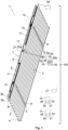
- an installation 100 in accordance with an embodiment of the invention, installed in a building, not shown.
- This installation 100 comprises an opening, window or door, equipped with a screen 2 belonging to a blackout device 1, in particular a slatted blind.
- the concealment device 1 may be, in particular, a pleated blind, a roller shutter, a rolling gate, a grille, a door or even a hinged shutter.
- the occultation device 1 is preferably arranged inside the building.
- the occultation device 1 is arranged outside the building.
- the occultation device 1 comprises blades 3, in particular adjustable ones.
- the screening device 1 further comprises a load bar 4.
- the screen 2 is formed of the blades 3 and the load bar 4.
- the load bar 4 makes it possible to exert tension on the screen 2.
- the load bar 4 is fixed at a lower end of the screen 2, in particular in an assembled configuration of the occulting device 1 in the installation 100.
- the screen 2 includes a final blade replacing the load bar 4, the latter being able to be weighted.
- the occulting device 1 comprises drive cords 5 configured to allow vertical movement of the blades 3 and the load bar 4.
- the drive cords 5 may also be called laces.
- the blades 3 respectively comprise openings, not shown, for the passage of each drive cord 5.
- the occultation device 1 further comprises orientation cords 6 configured to allow the orientation of the blades 3.
- the orientation cords 6 are also called ladders.
- each blade 3 of the screen 2 rests on a portion of orientation cord 6, in particular horizontal and which can be called a bar, connecting two strands of orientation cord 6, in particular vertical.
- orientation cords 6 make it possible to guarantee regular vertical spacing of the blades 3 of the screen 2.
- the orientation of the 3 blades allows, in particular, the adjustment of the brightness inside a room of the building.
- the concealing device 1 comprises two slides. Each of the slides is arranged along one side of the screen 2 of the concealing device 1.
- the slides are configured to cooperate with the slats 3 of the screen 2, so as to guide the slats 3, during the deployment and retraction of the screen 2.
- the blades 3 are guided by two cables. Each of the cables is arranged along one side of the screen 2 of the occulting device 1.
- the occulting device 1 comprises a motorized drive device 7.
- the motorized drive device 7 comprises at least one actuator electromechanical actuator 8.
- the electromechanical actuator 8 is configured to drive, in other words, moves the screen 2.
- the electromechanical actuator 8 makes it possible to lower or raise the slats 3 and the load bar 4, in other words to deploy or fold the screen 2, according to a vertical movement.
- the electromechanical actuator 8 also makes it possible to orient the slats 3.
- the occulting device 1 further comprises a rail 9, inside which the motorized drive device 7 is arranged, in particular the electromechanical actuator 8, in particular in an assembled configuration of the occulting device 1.
- the rail 9 is arranged, in other words is configured to be arranged, above the screen 2, in particular in the assembled configuration of the occulting device 1.
- rail 9 is arranged above the building opening, or in the upper part of the building opening.
- the rail 9 comprises at least one bottom wall 9a and two side walls 9b.
- rail 9 has a “U” shaped section.
- the motorized drive device 7 further comprises a plurality of winders.
- the winders are configured to wind and unwind the drive cords 5, so as to cause the vertical movement of the blades 3 and the load bar 4.
- the motorized drive device 7 comprises two winders, not visible on the Figure 1 .
- the number of reels is not limiting and may be different, in particular greater than two.
- the drive cords 5 are connected, on the one hand, to the load bar 4 and, on the other hand, to the winders.
- each drive cord 5 is connected to the load bar 4 and the upper end of each drive cord 5 is connected to one of the winders.
- the winders are arranged inside the rail 9.
- the motorized drive device 7 comprises tilting devices 13, generally called “tilters”. Each reel is respectively arranged inside a tilter 13. This is why the reels are not visible at the Figure 1 .
- rockers 13 are arranged, in other words are configured to be arranged, inside the rail 9, in particular in the assembled configuration of the concealing device 1.
- the motorized drive device 7 comprises two rockers 13.
- the number of rockers is not limiting and may be different, in particular strictly greater than two. In the case where the number of rockers is greater than or equal to two, the electromechanical actuator may be arranged between two of the rockers.
- each rocker 13 is arranged on either side of the electromechanical actuator 8.
- each rocker 13 is arranged in the vicinity of one end of the rail 9, in the longitudinal direction thereof.
- the rockers 13 are configured to drive the orientation cords 6 in rotation, over a limited rotation angle value range, so as to orient the blades 3.
- the motorized drive device 7, in particular the electromechanical actuator 8 is controlled by a control unit.
- the control unit is configured to control, i.e., command, the motorized drive device 7, in particular the electromechanical actuator 8.
- the control unit may be, for example, a local control unit 14 or a central control unit 15.
- the local control unit 14 can be connected, by wired or wireless connection, to the central control unit 15.
- the central control unit 15 can control the local control unit 14, as well as other similar local control units distributed throughout the building.
- the motorized drive device 7 is preferably configured to execute the movement commands, in particular for raising or lowering and, possibly, for orientation, of the screen 2 of the occulting device 1, which can be issued, in particular, by the local control unit 14 or the central control unit 15.
- the installation 100 and, more particularly, the concealment device 1 comprises either the local control unit 14, or the central control unit 15, or the local control unit 14 and the central control unit 15.
- Means for controlling the electromechanical actuator 8, allowing the movement of the screen 2 of the occultation device 1 as well as the orientation of the blades 3 of the screen 2, comprise at least one electronic control unit 19, as illustrated in figures 3 , 4 , 6 And 8 .
- the electronic control unit 19 is capable of putting into operation an electric motor 18 of the electromechanical actuator 8 and, in particular, allowing the supply of electrical energy to the electric motor 18.
- the electronic control unit 19 controls, in particular, the electric motor 18, so as to open or close the screen 2, as well as to orient the blades 3 of the screen 2, as described previously.
- the electronic control unit 19 comprises at least one communication module 49, in particular for receiving control orders, the control orders being emitted by an order transmitter, such as the local control unit 14 or central control unit 15, these orders being intended to control the motorized drive device 7.
- the communication module 49 of the electronic control unit 19 is of the wired type, in other words it allows the reception and, possibly, the transmission of control orders transmitted by wired means.
- the electronic control unit 19, the local control unit 14 and/or the central control unit 15 can be in communication with a weather station, not shown, arranged inside the building or remote outside the building, including, in particular, one or more sensors which can be configured to determine, for example, a temperature, a brightness or even a wind speed, in the case where the weather station is remote outside the building.
- the electronic control unit 19, the local control unit 14 and/or the central control unit 15 may also be in communication with a server 27, so as to control the electromechanical actuator 8 according to data made available remotely via a communication network, in particular an internet network which can be connected to the server 27.
- the electronic control unit 19 can be controlled from the local control unit 14 or central control unit 15.
- the local control unit 14 or central control unit 15 is provided with a control keyboard.
- the control keyboard of the local control unit 14 or central control unit 15 comprises one or more selection elements 50 and, optionally, one or more display elements 51.
- the selection elements may be push buttons or sensitive keys
- the display elements may be light-emitting diodes
- an LCD display (acronym for the English term “Liquid Crystal Display”) or TFT display (acronym for the English term “Thin Film Transistor”). Selection and display elements can also be carried out using a touch screen.
- the local control unit 14 or central control unit 15 comprises at least one communication module 48.
- the communication module 48 of the local control unit 14 or central control unit 15 is configured to transmit, in other words emit, control orders, in particular by wired means.
- the communication module 48 of the local control unit 14 or central control unit 15 can also be configured to receive, in other words receives, control orders, in particular via the same means.
- the communication module 48 of the local control unit 14 or central control unit 15 is hereinafter referred to as the first communication module.
- the communication module 49 of the electronic control unit 19 is hereinafter referred to as the second communication module.
- the first communication module 48 of the local control unit 14 or central control unit 15 is configured to communicate, in other words communicates, with the second communication module 49 of the electronic control unit 19.
- the first communication module 48 of the local control unit 14 or central control unit 15 exchanges control orders with the second communication module 49 of the electronic control unit 19, either in a unidirectional manner or in a bidirectional manner.
- the local control unit 14 is a control point, which may be fixed or mobile.
- a fixed control point may be a control box intended to be fixed to a facade of a wall of the building or to a face of the fixed frame of a window or a door.
- a mobile control point may be a remote control, a smartphone or a tablet.
- the local control unit 14 or central control unit 15 further comprises a controller 52.
- the control means of the electromechanical actuator 8 comprise hardware and/or software means.
- the hardware means may comprise at least one microcontroller 29, as illustrated in Figure 3 .
- the motorized drive device 7, in particular the electronic control unit 19, is preferably configured to execute movement control orders, in particular for deploying or retracting the screen 2 of the occulting device 1, as well as blade orientation 3. These control orders can be issued, in particular, by the local control unit 14 or by the central control unit 15.
- the motorized drive device 7 can be controlled by the user, for example by receiving a control command corresponding to pressing the or one of the selection elements 50 of the local 14 or central 15 control unit.
- the motorized drive device 7 can also be controlled automatically, for example by receiving a control command corresponding to at least one signal from at least one sensor, not shown, and/or a signal from a clock, not shown.
- the sensor and/or the clock can be integrated into the local control unit 14 or the central control unit 15.
- the senor and/or the clock are considered to correspond to a control unit, in particular a local control unit 14.
- the electromechanical actuator 8 comprises, among other things, the electric motor 18 and the electronic control unit 19.
- the electric motor 18 is represented by its casing at figures 3 And 4 , without details of its internal constituent elements, which are known per se.
- the electric motor 18 comprises a rotation shaft 47.
- the rotation shaft 47 of the electric motor 18 is configured to be rotated, i.e. is rotated, about an axis of rotation X.
- the rotation shaft 47 protrudes at the two opposite ends of the electric motor 18.
- the electric motor 18 comprises a rotor and a stator, not shown, positioned coaxially around the axis of rotation X. Furthermore, the rotor of the electric motor 18 is coupled or integrated with the rotation shaft 47 of the electric motor 18.
- the rotation axis X is also the rotation axis of the winders, in a mounted configuration of the motorized drive device 7.
- the electromechanical actuator 8 makes it possible to move the screen 2 of the occulting device 1, in particular in a vertical movement, as well as to orient the slats 3 of the screen 2.
- the electromechanical actuator 8 comprises an electrical power supply cable 10.
- the electromechanical actuator 8 is configured to be powered, in other words is powered, with electrical energy by a main electrical power source 54, via the electrical power supply cable 10.
- the main electrical power source 54 may be a mains electrical power supply network or a battery, which may be recharged, for example, by a photovoltaic panel or a charger, not shown.
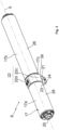
- the electromechanical actuator 8 further comprises a casing 17, in particular tubular.
- the casing 17 of the electromechanical actuator 8 is cylindrical in shape and, more particularly, has a circular cross-section.
- the casing 17 of the electromechanical actuator 8 is parallelepipedal in shape.
- the electromechanical actuator 8 further comprises at least one output shaft 20.
- the electromechanical actuator 8 further comprises at least one reducer 12.
- the reducer 12 comprises at least one reduction stage.
- the reduction stage may be an epicyclic type gear train.
- the type and number of reduction stages of the reducer are not limited.
- the reduction stages may be, for example, two or three in number.
- the electromechanical actuator 8 comprises two reducers 12 and two output shafts 20, so that each output shaft 20 drives one of the winders in rotation.
- Each output shaft 20 opens onto one side of the housing 17 of the electromechanical actuator 8.
- Each output shaft 20 is connected to a drive shaft 11 of one of the winders by means of coupling elements, not shown.
- the coupling elements of each output shaft 20 to one of the drive shafts 11 are, for example, screw coupling elements.
- Each reel is thus driven in rotation, at the level of one of the rockers 13, by one of the drive shafts 11 coupled with one of the output shafts 20 of the electromechanical actuator 8.
- the electromechanical actuator 8 further comprises a brake 46, as illustrated in figures 3 And 4 .
- a brake 46 as illustrated in figures 3 And 4 .
- the brake 46 being represented to the right of the electric motor 18 at the Figure 3 and to the left of this one to the Figure 4 .
- the brake 46 may be a magnetic brake, a spring brake, a cam brake or an electromagnetic brake.
- the electric motor 18 and, possibly, the reducers 12 and the brake 46 are arranged inside the casing 17 of the electromechanical actuator 8.
- the electromechanical actuator 8 further comprises a switching device 21.
- the screen 2 comprises the plurality of blades 3, including a first blade 3h.
- the first blade 3h faces the bottom wall 9a of the rail 9, in particular in the assembled configuration of the occulting device 1.
- the first blade 3h of the screen 2 corresponds to the upper blade 3 of the screen 2.
- a high position in particular a safety position, corresponds to the first slat 3h of the screen 2 resting against an element of the switching device 21.
- the switching device 21 makes it possible, in particular, to determine when the screen 2 has reached the upper position.
- An upper end position in particular an operating position, corresponds to a predetermined upper end position, in particular by means of an end-of-travel detection device 35.
- a low end-of-travel position corresponds to a predetermined low end-of-travel position, in particular, by means of the end-of-travel detection device 35, or to the load bar 4 being pressed against a threshold of the opening of the building, or even to the complete deployment of the screen 2.
- the end-of-travel detection device 35 may be of the magnetic type and assembled on the rotation shaft 47 of the electric motor 18.
- Such an end-of-travel detection device 35 comprises at least one wheel and Hall effect sensors.
- the end-of-travel detection device 35 can be assembled on at least one of the output shafts 20 of the electromechanical actuator 8.
- the type of end-of-travel detection device is not limiting and may be different, in particular of the time type and produced through the microcontroller 29 of the electronic control unit 19.
- the switching device 21 comprises a housing 22.
- the housing 22 comprises two half-shells 22c, 22d, as illustrated in figures 2 And 4 .
- These two half-shells 22c, 22d are assembled, in other words configured to be assembled together, in particular in an assembled configuration of the electromechanical actuator 8, by means of fixing elements 36, for example by elastic snap-fastening.
- the casing 17 of the electromechanical actuator 8 comprises at least a first part 17a and a second part 17b.
- the housing 22 of the switching device 21 is arranged, along the axis of rotation X, between the first part 17a of the casing 17 and the second part 17b of the casing 17.
- the housing 22 of the switching device 21 forms a third part 17c of the casing 17.
- the casing 17 is made at least partly of a metallic material.
- the material of the electromechanical actuator casing is not limiting and may be different. In particular, it may be a plastic material.
- the first and second parts 17a, 17b of the housing 17 are made of a metallic material. Furthermore, the third part 17c of the housing 17, formed by the housing 22 of the switching device 21, is made of a plastic material.
- the housing 22 of the switching device 21 is fixed to the first and second parts 17a, 17b of the casing 17.
- the housing 22 is fixed to the first and second parts 17a, 17b of the casing 17 by fitting, in particular by inserting a first end 22a of the housing 22 into the first part 17a of the casing 17, up to a first shoulder 37 of the housing 22, and by inserting a second end 22b of the housing 22 into the second part 17b of the casing 17, up to a second shoulder 38 of the housing 22.
- the first and second ends 22a, 22b are formed, in part, by the half-shell 22c and, in part, by the half-shell 22d.
- the type of attachment of the housing to the first and second parts of the casing is not limiting and may be different. In particular, it may be an attachment by means of screw-on or elastic snap-fastening elements.
- the housing 22 of the switching device 21 is tubular.
- the housing 22 of the switching device 21 is cylindrical in shape and, more particularly, has a circular cross-section.
- the housing 22 of the switching device 21 is parallelepipedal in shape.
- the casing 17 of the electromechanical actuator 8 is made in a single part, that is to say is of the monobloc type, and, more particularly, is without a housing 22 for the switching device 21.
- the switching device 21 is assembled directly, i.e. without an intermediate housing, on the casing 17 of the electromechanical actuator 8, in particular in the assembled configuration of the electromechanical actuator 8.
- the casing 17 defines at least one wall 28, 39.
- first and second parts 17a, 17b of the casing 17 together define a first wall 28, in particular of circular section.
- the third part 17c of the casing 17, formed by the housing 22 of the switching device 21, defines a second wall 39, in particular of circular section in which flats are provided.
- the wall 39 of the casing 17, in particular of the third part 17c of the casing 17, comprises at least one opening 40.
- the opening 40 is provided in a flat of the wall 39 of the third part 17c of the casing 17.
- the opening 40 of the wall 39 of the casing 17 is provided in a lower part of the casing 17, in particular in an assembled configuration of the electromechanical actuator 8 in the rail 9 of the concealment device 1.
- the opening 40 of the wall 39 of the casing 17 is arranged opposite the first blade 3h of the concealment device 1.
- the casing 17 defines a lower wall, an upper wall, a first side wall and a second side wall.
- the opening 40 is, preferably, formed in the lower wall of the casing 17.
- the switching device 21 further comprises a first member 23 and a second member 24.
- the first member 23 is integral with the casing 17 and, more particularly, with the wall 39 of the casing 17.
- the first member 23 is fixed, in other words configured to be fixed, on the wall 39 of the casing 17 by means of removable fixing elements 25, in particular in the assembled configuration of the electromechanical actuator 8. Furthermore, the first member 23 is arranged opposite the opening 40 of the wall 39 of the casing 17, in particular in the assembled configuration of the electromechanical actuator 8.
- the removable fixing elements 25 are elastic snap-fastening fixing elements.
- each removable fixing element 25 is constituted by an elastic tab provided on the first member 23 and cooperating, in other words configured to cooperate, with an edge 40a of the opening 40 of the wall 39. of the casing 17 and, more particularly, with a notch of the opening 40 of the wall 39 of the casing 17.
- the first member 23 comprises two elastic tabs 25 cooperating, in other words configured to cooperate, respectively with the edge 40a of the opening 40 of the wall 39 of the casing 17.
- the number and type of removable fastening elements of the first member on the wall of the casing are not limiting and may be different. This number may be strictly greater than two.
- the removable fastening elements may be screw fastening elements.
- the second member 24 is movable relative to the first member 23, in particular in the assembled configuration of the electromechanical actuator 8.
- the second member 24 is movable relative to the first member 23 according to a translational movement T.
- the translational movement T is radial to the axis of rotation X, as illustrated in Figure 3 .
- the first member 23 comprises a housing 43, inside which the second member 24 is partially arranged. Furthermore, the first member 23 comprises a barrel 44 arranged in the center of the housing 43 and configured to cooperate with a blind housing 16 formed in the second member 24.
- the second member 24 is guided inside the housing 43 of the first member 23 by the complementarity of shapes of the first and second members 23, 24, in particular by the contour of the second member 24 and the contour of the housing 43 of the first member 23. Furthermore, the second member 24 is centered relative to the first member 23 by means of the barrel 44 of the first member 23 sliding inside the blind housing 16 formed in the second member 24. Furthermore, the second member 24 may comprise a central pin configured to slide inside a central bore of the barrel 44 of the first member 23.
- the first member 23 and the second member 24 form a subassembly 26 of the switching device 21.
- the subassembly 26 of the switching device 21 is arranged outside the casing 17 and, more particularly, the housing 22.
- Such a subassembly 26 of the switching device 21 is generally called a “mushroom”.
- the second member 24 of the switching device 21 is moved, in other words configured to be moved, according to the translation movement T, by the first blade 3h of the screen 2, relative to the first member 23, when the screen 2 reaches the high position.
- the movement of the second member 24 relative to the first member 23, in a direction of bringing the second member 24 closer to the casing 17, results from a movement of the first blade 3h of the screen 2 towards the high position, during the activation of the electromechanical actuator 8.
- the movement of the first blade 3h of the screen 2 is implemented by the activation of the electromechanical actuator 8 and the winding of the drive cords 5 around the winders.
- the electronic control unit 19 commands the stopping of the electric motor 18 of the electromechanical actuator 8.
- At least a part of the switching device 21 is arranged outside the rail 9.
- the part of the switching device 21 arranged outside the rail 9 corresponds to at least a part of the subassembly 26 of the switching device 21.
- another part of the switching device 21 is arranged inside the rail 9, in particular the casing 17, as well as the elements assembled inside it.
- the second member 24 of the switching device 21 extends under the bottom wall 9a of the rail 9, in particular in the assembled configuration of the occulting device 1 in the installation 100.
- the subassembly 26 of the switching device 21, which is not visible on the Figure 1 passes through an opening, not shown, made in the bottom wall 9a of the rail 9.
- the second member 24 of the switching device 21 is moved, in other words configured to be moved, between a first position, called “rest”, in which no contact is made between the second member 24 and the first blade 3h of the screen 2, and a second position, called “screen 2 high position detection", in which the first blade 3h of the screen 2 is in contact with the second member 24.
- the switching device 21 further comprises an elastic return element 45 of the second member 24 relative to the first member 23, so as to maintain by default the second member 24 in its rest position, in particular in the assembled configuration of the electromechanical actuator 8, in particular as long as the first blade 3h of the screen 2 is not in contact with the second member 24.
- the elastic return element 45 maintains or returns, in other words is configured to maintain or return, the second member 24 to its rest position.
- the elastic return element 45 exerts, on the second member 24, a radial force at the axis of rotation X, directed downwards at the Figure 3 and parallel to the translational movement T.
- the elastic return element 45 is a spring, for example, in the form of a spiral.
- the second member 24 is configured to return to the rest position relative to the first member 23 by gravity, in particular in the assembled configuration of the concealment device 1 in the installation 100.
- the second member 24 is configured to move from its second position to its first position relative to the first member 23, under the effect of its own weight.
- the second member 24 comprises stops, not shown, cooperating, in other words configured to cooperate, with stops of the first member 23, in particular in the assembled configuration of the electromechanical actuator 8, when the second member 24 is in the rest position relative to the first member 23.
- the cooperation of the stops of the second member 24 with the stops of the first member 23 makes it possible to limit a displacement stroke of the second member 24 relative to the first member 23.
- the stops of the second member 24 cooperate, in other words are configured to cooperate, with the stops of the first member 23, when the second member 24 is held in the rest position relative to the first member 23, by means of the elastic return element 45.
- each of the first and second members 23, 24 comprises two stops.
- the number of stops of each of the first and second members is not limiting and may be different. It may be, for example, greater than or equal to three.
- the electronic control unit 19 comprises at least one switch 41 and a printed circuit board 42.
- the switch 41 makes it possible to detect the high position of the screen 2 of the occultation device 1.
- This switch 41 can also be called the first switch.
- the electronic control unit 19 comprises a single switch 41 for detecting the high position of the screen 2 of the occultation device 1.
- switch 41 is of the electromechanical type.
- the switch 41 is electrically connected to the printed circuit board 42 by electrical conductors, not shown.
- the switch 41 is actuated, in other words configured to be actuated, by means of the second member 24 of the switching device 21 through the opening 40 provided in the wall 39 of the casing 17, as a function of a position of the second member 24 relative to the first member 23, in particular in the assembled configuration of the electromechanical actuator 8.
- the switch 41 is assembled, in other words configured to be assembled, on the printed circuit board 42, in particular in the assembled configuration of the electromechanical actuator 8.
- the electronic control unit 19 comprises the microcontroller 29.
- microcontroller 29 is assembled on the printed circuit board 42, in particular in the assembled configuration of the electromechanical actuator 8.
- the microcontroller 29 comprises at least one memory, not shown.
- the electronic control unit 19 comprises at least a first part 19a and a second part 19b.
- the first part 19a of the electronic control unit 19 is arranged inside the third part 17c of the casing 17 of the electromechanical actuator 8, formed by the housing 22 of the switching device 21, in particular in the assembled configuration of the electromechanical actuator 8.
- the second part 19b of the electronic control unit 19 is arranged inside at least one other part 17a, 17b of the casing 17 of the electromechanical actuator 8, in particular in the assembled configuration of the electromechanical actuator 8.
- the first part 19a of the electronic control unit 19 is arranged inside the third part 17c of the casing 17, in this case of the housing 22 of the switching device 21, and the second part 19b ... third part 19c of the electronic control unit 19 is arranged inside the third part 17c of the casing 17, in this case control 19 is arranged inside the first and second parts 17a, 17b of the casing 17. Furthermore, the second part 19b of the electronic control unit 19 is bipartite and arranged on either side of the first part 19a of the electronic control unit 19.
- the electromechanical actuator 8 comprises at least one electrical connection device 30.
- the electrical connection device 30 is electrically connected to the electronic control unit 19.
- the electrical connection device 30 is arranged opposite the opening 40 of the wall 39 of the casing 17, in particular in the assembled configuration of the electromechanical actuator 8. Furthermore, the electrical connection device 30 is accessible through the opening 40 of the wall 39 of the casing 17, in particular following removal of the first and second members 23, 24 relative to the wall 39 of the casing 17, by dismantling the removable fixing elements 25 relative to the wall 39 of the casing 17.
- the removal of the first and second members 23, 24 relative to the wall 39 of the casing 17 is implemented by means of the removable fixing elements 25 which are disassembled, in other words separated, from the wall 39 of the casing 17.
- the removable fixing elements 25 are made inactive to allow the first and second members 23, 24 to be separated from the wall 39 of the casing 17. This makes it possible to achieve the configuration of the Figure 6 where the first and second organs 23, 24 are omitted.
- the removal of the first and second members 23, 24 relative to the wall 39 of the casing 17 is implemented by exerting pressure on the removable fixing elements 25, so as to release the latter relative to the wall 39 of the casing 17.
- electromechanical actuator 8 facilitates access to the electrical connection device 30, during a maintenance or repair intervention on the electromechanical actuator 8, without having to dismantle the electromechanical actuator 8 with respect to the occulting device 1.
- the electromechanical actuator 8 makes it possible, on the one hand, to detect a high position of the screen 2 of the occulting device 1 by means of the switching device 21 and the electronic control unit 19 and, on the other hand, to be able to access the electrical connection device 30 through the opening 40 provided in the casing 17, following the dismantling of the first and second members 23, 24 of the switching device 21 relative to the casing 17.
- the positioning of the opening 40 of the wall 39 of the casing 17 in the lower part of the casing 17, in particular in the assembled configuration of the electromechanical actuator 8 in the rail 9 of the concealing device 1, facilitates access to the electrical connection device 30 from below, during a maintenance or repair operation of the electromechanical actuator 8, without having to dismantle the electromechanical actuator 8 with respect to the concealing device 1.
- the positioning of the opening 40 of the wall 39 of the casing 17 in the lower part of the casing 17, in particular in the assembled configuration of the electromechanical actuator 8 in the rail 9 of the concealing device 1, also makes it easier to view the electrical connection device 30, following dismantling of the first and second members 23, 24 of the switching device 21 with respect to the casing 17.
- the concealment device 1 comprises at least one configuration or maintenance terminal 32, visible at the Figure 1 .
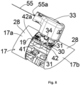
- the configuration or maintenance terminal 32 comprises at least one electronic unit 53, an electrical connection cable 55 and an electrical socket 33.
- the electrical socket 33 is, on the one hand, configured to be electrically connected, in other words is electrically connected, with the electrical connection device 30 of the electromechanical actuator 8 and, on the other hand, configured to be electrically connected, in other words is electrically connected, with the electronic unit 53 of the configuration or maintenance terminal 32, via the electrical connection cable 55.
- the configuration or maintenance terminal 32 may be, for example, a configuration tool, a computer, a smartphone or a tablet.
- the switching device 21 is removed from the casing 17, in particular by actuating the removable fixing elements 25.
- the electrical socket 33 of the configuration or maintenance terminal 32 is electrically connected to the electrical connection device 30 of the electromechanical actuator 8, the electrical socket 33 is arranged between the first blade 3h of the screen 2 and the bottom wall 9a of the rail 9. This is why it is not visible at the Figure 1 . On the other hand, it is visible at the figure 8 .
- the configuration or maintenance terminal 32 further comprises a control keyboard, not shown, which may be, for example, similar to that of the local control unit 14 or central control unit 15.
- the configuration or maintenance terminal 32 When the configuration or maintenance terminal 32 is electrically connected to the electromechanical actuator 8, at least by means of the electrical connection cable 55 and the electrical socket 33 of the configuration or maintenance terminal 32 and the electrical connection device 30 of the electromechanical actuator 8, the configuration or maintenance terminal 32 supplies electrical energy, in other words is configured to supply electrical energy, to the electronic control unit 19 of the electromechanical actuator 8.
- the configuration or maintenance terminal 32 forms a secondary electrical power source for the electronic control unit 19 of the electromechanical actuator 8.
- a value of a voltage of the electrical power supply provided by the configuration or maintenance terminal 32 to the electronic control unit 19 of the electromechanical actuator 8 is strictly lower than a value of a voltage of the electrical power supply provided by the main electrical power source 54 to the electromechanical actuator 8, via the electrical power supply cable 10.
- the occultation device 1 makes it possible to dispense with the electrical power supply of the electromechanical actuator 8 from the main electrical power source 54, via the electrical power supply cable 10, when the configuration or maintenance terminal 32 is electrically connected to the electromechanical actuator 8.
- the electrical connection between the configuration or maintenance terminal 32 and the electronic control unit 19 of the electromechanical actuator 8 allows an autonomous electrical power supply to the electronic control unit 19 of the electromechanical actuator 8 by the configuration or maintenance terminal 32, i.e. independent of the electrical power supply provided by the main electrical power source 54, via the electrical power supply cable 10.
- the value of the voltage of the electrical power supply provided by the configuration or maintenance terminal 32 to the electronic control unit 19 of the electromechanical actuator 8 corresponds to a value of a voltage of a supply of electrical energy for operation of the microcontroller 29 of the electronic control unit 19 of the electromechanical actuator 8.
- the value of the voltage of the operating power supply of the microcontroller 29 may be of the order of three point three volts (3.3 V) or five volts (5 V).
- the value of the voltage of the electrical power supply provided by the configuration or maintenance terminal 32 to the electronic control unit 19 of the electromechanical actuator 8 is strictly lower than a value of a voltage of an electrical power supply for operating the electric motor 18.
- this value of the voltage of the electrical power supply provided by the configuration or maintenance terminal 32 to the electronic control unit 19 of the electromechanical actuator 8 does not allow rotational driving of the rotation shaft 47 of the electric motor 18.
- this value of the voltage of the electrical power supply provided by the configuration or maintenance terminal 32 to the electronic control unit 19 of the electromechanical actuator 8 makes it possible to prevent the electronic control unit 19 of the electromechanical actuator 8 from detecting the electrical power supply provided by the configuration or maintenance terminal 32 as being the power supply provided by the main electrical power source 54 and that this electronic control unit 19 attempts to trigger operation of the electric motor 18.
- the value of the operating supply voltage of the electric motor 18 may be of the order of 24 volts (24 V), in particular in the case where the electric motor 18 is supplied with direct current.
- the electronic unit 53 of the configuration or maintenance terminal 32 is configured to communicate, in other words communicates, with the electronic control unit 19 of the electromechanical actuator 8, by means of the electrical connection cable 55, following the electrical connection of the electrical socket 33 of the configuration or maintenance terminal 32 with the electrical connection device 30 of the electromechanical actuator 8.
- the communication between the configuration or maintenance terminal 32 and the electronic control unit 19 is implemented by a wired connection.
- This wired connection makes it possible to avoid electromagnetic interference, in particular radioelectric interference, compared to the case where a connection between the configuration or maintenance terminal 32 and the electronic control unit 19 is implemented by a wired connection.
- maintenance 32 and the electronic control unit 19 of the electromechanical actuator 8 is implemented by means of wireless communication.
- the communication between the configuration or maintenance terminal 32 and the electronic control unit 19 is bidirectional.
- the communication between the configuration or maintenance terminal 32 and the electronic control unit 19 is unidirectional.
- the configuration or maintenance terminal 32 is configured to be supplied with electrical energy, in other words is supplied with electrical energy, from a mains electricity supply network, which may be the same as that supplying electrical energy to the electromechanical actuator 8, or from a battery, in particular different from that supplying electrical energy to the electromechanical actuator 8 and which may be recharged, for example, by a photovoltaic panel or a charger, not shown.
- a mains electricity supply network which may be the same as that supplying electrical energy to the electromechanical actuator 8, or from a battery, in particular different from that supplying electrical energy to the electromechanical actuator 8 and which may be recharged, for example, by a photovoltaic panel or a charger, not shown.
- the configuration or maintenance terminal 32 is configured to reset or adjust at least part of the operating parameters of the electromechanical actuator 8, at least via the electrical connection cable 55 and the electrical socket 33 of the configuration or maintenance terminal 32 and the electrical connection device 30 of the electromechanical actuator 8.
- the electromechanical actuator 8 in particular the electronic control unit 19 of the electromechanical actuator 8, is supplied with electrical energy from the configuration or maintenance terminal 32, corresponding to the secondary electrical energy supply source, when resetting or when adjusting the operating parameters of the electromechanical actuator 8.
- the electromechanical actuator 8 in particular the electronic control unit 19 of the electromechanical actuator 8, is not supplied with electrical energy from the main electrical energy supply source 54, via the electrical power supply cable 10.
- the resetting or adjustment of the operating parameters of the electromechanical actuator 8 is implemented following the electrical connection of the electrical socket 33 with the electrical connection device 30 of the electromechanical actuator 8.
- the operating parameters of the electromechanical actuator 8 are stored in a memory of the electronic control unit 19, in particular a memory of the microcontroller 29.
- the operating parameters of the electromechanical actuator 8 may be, for example, a movement speed of the screen 2, an obstacle detection sensitivity or the upper or lower end position of the screen 2.
- the configuration or maintenance terminal 32 is configured to allow a diagnosis of the electromechanical actuator 8, from operating data of the electromechanical actuator 8, at least via the electrical connection cable 55 and the electrical socket 33 of the configuration or maintenance terminal 32 and the electrical connection device 30 of the electromechanical actuator 8.
- the electromechanical actuator 8 in particular the electronic control unit 19 of the electromechanical actuator 8, is supplied with electrical energy from the configuration or maintenance terminal 32, corresponding to the secondary electrical energy supply source, when diagnosing the operating data of the electromechanical actuator 8.
- the electromechanical actuator 8 in particular the electronic control unit 19 of the electromechanical actuator 8, is not supplied with electrical energy from the main electrical energy supply source 54, via the electrical power supply cable 10.
- diagnosis of the operating data of the electromechanical actuator 8 is implemented following the electrical connection of the electrical socket 33 with the electrical connection device 30 of the electromechanical actuator 8.
- the operating data of the electromechanical actuator 8 are stored in a memory of the electronic control unit 19, in particular a memory of the microcontroller 29.
- the operating data of the electromechanical actuator 8 may be, for example, a temperature of the electromechanical actuator 8, which can be measured by a temperature probe, not shown, a number of operating cycles of the electromechanical actuator 8 over a predetermined period of time or a current consumption over a predetermined period of time.
- the configuration or maintenance terminal 32 is configured to update part of a software stored in a memory of the electronic control unit 19 of the electromechanical actuator 8, in particular a memory of the microcontroller 29, or to replace a software stored in a memory of the electronic control unit 19 of the electromechanical actuator 8, in particular a memory of the microcontroller 29, at least via the electrical connection cable 55 and the electrical socket 33 of the configuration or maintenance terminal 32 and the electrical connection device 30 of the electromechanical actuator 8.
- the electromechanical actuator 8, in particular the electronic control unit 19 of the electromechanical actuator 8, is supplied with electrical energy from the configuration or maintenance terminal 32, corresponding to a secondary electrical energy supply source, when updating or replacing the software stored in the memory of the electronic control unit 19 of the electromechanical actuator 8.
- the electromechanical actuator 8, in particular the electronic control unit 19 of the electromechanical actuator 8, is not supplied with electrical energy from the main electrical energy supply source 54, via the electrical power supply cable 10.
- the updating or replacement of the software stored in the memory of the electronic control unit 19 of the electromechanical actuator 8 is implemented following the electrical connection of the electrical socket 33 with the electrical connection device 30 of the electromechanical actuator 8.
- the configuration or maintenance terminal 32 in particular the electronic unit 53 of the configuration or maintenance terminal 32, is configured to put into operation, in other words puts into operation, software or an application, so as to carry out a reset or an adjustment of the operating parameters of the electromechanical actuator 8, carry out a diagnosis of the operating data of the electromechanical actuator 8 and/or carry out an update or a replacement of the software stored in a memory of the electronic control unit 19 of the electromechanical actuator 8.
- the configuration or maintenance terminal 32 is in communication with the server 27, so as to download the software following data made available remotely via a communication network, in particular an internet network which can be connected to the server 27.
- the electrical connection cable 55 comprises a first end 55a and a second end 55b.
- the electrical socket 33 is connected electrically, in other words is configured to be electrically connected, to the first end 55a of the electrical connection cable 55.
- the configuration or maintenance terminal 32 further comprises a first electrical connection port 56.
- the first electrical connection port 56 is electrically connected, in other words is configured to be electrically connected, to the electronic unit 53 of the configuration or maintenance terminal 32.
- the second end 55b of the electrical connection cable 55 is electrically connected, in other words is configured to be electrically connected, to a second electrical connection port 57.
- the second electrical connection port 57 of the electrical connection cable 55 is electrically connected, in other words is configured to be electrically connected, to the first electrical connection port 56 of the configuration or maintenance terminal 32, in particular when this configuration or maintenance terminal 32 is electrically connected to the electronic unit 19 of the electromechanical actuator 8, at least via the electrical connection cable 55, the electrical socket 33 and the electrical connection device 30.
- the first and second electrical connection ports 56, 57 are of the USB type (acronym for the English term “Universal Serial Bus”).
- the electrical connection between the configuration or maintenance terminal 32 and the electronic control unit 19 of the electromechanical actuator 8 can be standard, in particular in the case where the first and second electrical connection ports 56, 57 are “USB” type ports.
- the electrical connection cable 55 comprises at least one protection device 58.
- the protection device 58 is configured to protect, in other words protects, the electronic unit 53 of the configuration or maintenance terminal 32 and the electronic control unit 19 of the electromechanical actuator 8, when the electromechanical actuator 8 is electrically connected to the main electrical power source 54, via the electrical power supply cable 10, and when the configuration or maintenance terminal 32 is electrically connected to the electromechanical actuator 8, at least by means of the electrical connection cable 55 and the electrical socket 33 of the configuration or maintenance terminal 32 and the electrical connection device 30 of the electromechanical actuator 8.
- the protection device 58 makes it possible, on the one hand, to avoid damaging the electronic unit 53 of the configuration or maintenance terminal 32, in particular the electronic components dedicated to communication by means of the first and second electrical connection ports 56, 57 of the “USB” type, and, on the other hand, to avoid to damage the electronic control unit 19 of the electromechanical actuator 8.
- the protection device 58 makes it possible to electrically connect the configuration or maintenance terminal 32 to the electromechanical actuator 8, while the electromechanical actuator 8 is electrically connected to the main electrical power source 54, via the electrical power cable 10, in other words without having to electrically disconnect or unplug the electromechanical actuator 8 from the main electrical power source 54.
- the protection device 58 comprises at least one electronic card 59 and a protection component 60.
- the protection component 60 is mounted on the electronic card 59.
- the protection component 60 is a diode.
- the electronic card 59 of the protection device 58 comprises a plurality of electrical tracks, not shown.
- the electrical connection cable 55 comprises a plurality of electrical wires, not shown.
- the electronic card 59 of the protection device 58 comprises at least as many electrical tracks as the number of electrical wires of the electrical connection cable 55.
- each electrical wire of the electrical connection cable 55 is electrically connected, in other words is configured to be electrically connected, to one of the electrical tracks of the electronic card 59 of the protection device 58.
- the protection component 60 is mounted in parallel with the electrical tracks of the electronic card 59 of the protection device 58, electrically connected to the electrical wires of the electrical connection cable 55.
- the electrical connection device 30 comprises electrical connection points 31 provided on a face 42a of the printed circuit board 42.
- the electrical connection points 31 are electrical conductors of the printed circuit board 42.
- the electrical conductors of the printed circuit board 42 correspond to electrical tracks printed on the printed circuit board 42.
- the electrical connection device 30 comprises four electrical connection points 31. At the Figure 6 , only three of the electrical connection points 31 are shown.
- the number of electrical connection points is not limited and may vary. It may be, in particular, two, three or greater than or equal to five.
- the electrical socket 33 of the configuration or maintenance terminal 32 comprises pins cooperating, in other words configured to cooperate, with the electrical connection device 30 and, more particularly, with the electrical connection points 31 of the printed circuit board 42.
- the pins of the electrical socket 33 are electrically connected to the electrical tracks of the electronic card 59 of the protection device 58, in particular either directly, in the case not shown where the protection device 58 is integrated into the electrical socket 33, or by means of electrical wires of the electrical connection cable 55.
- the electrical connection points 31 of the printed circuit board 42 are electrically connected to ports of the microcontroller 29 by electrical tracks, not shown, printed on the printed circuit board 42.
- the electrical connection device 30 comprises an electrical connector.
- the electrical connector is electrically connected to the printed circuit board 42, for example by an electrical cable, or fixed to the printed circuit board 42 and, more particularly, soldered to the printed circuit board 42.
- the electrical socket 33 is equipped with an electrical connector complementary to that of the electrical connection device 30.
- the electrical socket 33 comprises removable fixing elements 34, only one of which is shown in the figure. figure 8
- the removable fixing elements 34 of the electrical socket 33 are configured to cooperate with the wall 39 of the casing 17, in particular in an assembled configuration of the electrical socket 33 with the electromechanical actuator 8.
- the removable fixing elements 34 of the electrical socket 33 are similar to the removable fixing elements 25 of the first member 23 of the switching device 21.
- the concealment device makes it possible to dispense with the electrical power supply of the electromechanical actuator from the main electrical power source, via the electrical power cable, when the configuration or maintenance terminal is electrically connected to the electromechanical actuator.
- the motorized drive device 7 comprises, in addition to a plurality of first winders of the drive cords 5, a plurality of second winders of the orientation cords 6.
- the drive cords 5 are connected, on the one hand, to the load bar 4 and, on the other hand, to the first winders.
- the orientation cords 6 are connected, on the one hand, to the load bar 4 and to the blades 3 and, on the other hand, to the second winders.
- the lower end of each drive cord 5 is connected to the load bar 4 and the upper end of each drive cord 5 is connected to one of the first winders, in particular in the assembled configuration of the occultation device 1 in the installation 100.
- each orientation cord 6 is connected to the load bar 4 and the upper end of each orientation cord 6 is connected to one of the second winders, in particular in the assembled configuration of the occultation device 1 in the installation 100.
- the first and second winders are arranged inside the rail 9.
- the motorized drive device 7 comprises two chains for driving and orienting the slats 3 of the screen 2, replacing the drive cords 5 and the orientation cords 6.
- each chain is arranged inside one of the slides, arranged along one side of the screen 2 of the concealment device 1.
- the communication module 49 of the electronic control unit 19 is configured to receive, in other words receives, and, possibly, to transmit, in other words transmits, control commands transmitted by wireless means, in particular, radio control commands.
- the communication module 48 of the local 14 or central 15 control unit is configured to transmit, in other words transmits, and, possibly, to receive, in other words receives, control commands, in particular by wireless means, for example radio.
Landscapes
- Engineering & Computer Science (AREA)
- Structural Engineering (AREA)
- Architecture (AREA)
- Civil Engineering (AREA)
- Operating, Guiding And Securing Of Roll- Type Closing Members (AREA)
- Transforming Electric Information Into Light Information (AREA)
- User Interface Of Digital Computer (AREA)
Claims (10)
- Verdunkelungsvorrichtung (1), mindestens umfassend:- einen Schirm (2),- eine motorisierte Antriebsvorrichtung (7), und- ein Konfigurations- oder Wartungsterminal (32),die motorisierte Antriebsvorrichtung (7) mindestens umfassend:- einen elektromechanischen Aktuator (8), wobei der elektromechanische Aktuator (8) konfiguriert ist, um den Schirm (2) beweglich anzutreiben, und- ein Stromversorgungskabel (10), wobei der elektromechanische Aktuator (8) konfiguriert ist, um über das Stromversorgungskabel (10) mit elektrischer Energie aus einer Hauptstromversorgungsquelle (54) versorgt zu werden,der elektromechanische Aktuator (8) mindestens umfassend:- eine elektronische Steuereinheit (19),- einen Elektromotor (18),- eine Ausgangswelle (20), und- eine elektrische Verbindungsvorrichtung (30), wobei die elektrische Verbindungsvorrichtung (30) elektrisch mit der elektronischen Steuereinheit (19) verbunden ist,das Konfigurations- oder Wartungsterminal (32) mindestens umfassend:- eine elektronische Einheit (53),- ein elektrisches Verbindungskabel (55), und- einen Stromanschluss (33), wobei der Stromanschluss (33) einerseits konfiguriert ist, um elektrisch mit der elektrischen Verbindungsvorrichtung (30) des elektromechanischen Aktuators (8) verbunden zu sein, und andererseits konfiguriert ist, um über das elektrische Verbindungskabel (55) elektrisch mit der elektronischen Einheit (53) des Konfigurations- oder Wartungsterminals (32) verbunden zu sein,dadurch gekennzeichnet,dass, wenn das Konfigurations- oder Wartungsterminal (32) zumindest über das elektrische Verbindungskabel (55) und den Stromanschluss (33) des Konfigurations- oder Wartungsterminals (32) und die elektrische Verbindungsvorrichtung (30) des elektromechanischen Aktuators (8), elektrisch mit dem elektromechanischen Aktuator (8) verbunden ist, das Konfigurations- oder Wartungsterminal (32) die elektronische Steuereinheit (19) des elektromechanischen Aktuators (8) mit elektrischer Energie versorgt, wobei das Konfigurations- oder Wartungsterminal (32) dann eine sekundäre Stromversorgungsquelle bildet,und dass ein Wert einer Spannung der elektrischen Energieversorgung, die von dem Konfigurations- oder Wartungsterminal (32) an die elektronische Steuereinheit (19) des elektromechanischen Aktuators (8) geliefert wird, strikt kleiner ist als ein Wert einer Spannung der elektrischen Energieversorgung, die von der Hauptstromversorgungsquelle (54) über das Stromversorgungskabel (10) an den elektromechanischen Aktuator (8) geliefert wird.
- Verdunkelungsvorrichtung (1) nach Anspruch 1, dadurch gekennzeichnet,dass die elektronische Steuereinheit (19) des elektromechanischen Aktuators (8) mindestens einen Mikrocontroller (29) umfasst,und dass der Wert der Spannung der elektrischen Energieversorgung, die von dem Konfigurations- oder Wartungsterminal (32) an die elektronische Steuereinheit (19) des elektromechanischen Aktuators (8) geliefert wird, einem Wert einer Spannung einer elektrischen Betriebsenergieversorgung des Mikrocontrollers (29) der elektronischen Steuereinheit (19) des elektromechanischen Aktuators (8) entspricht.
- Verdunkelungsvorrichtung (1) nach Anspruch 1 oder nach Anspruch 2, dadurch gekennzeichnet, dass der Wert der Spannung der elektrischen Energieversorgung, die von dem Konfigurations- oder Wartungsterminal (32) an die elektronische Steuereinheit (19) des elektromechanischen Aktuators (8) geliefert wird, strikt kleiner ist als ein Wert einer Spannung einer elektrischen Betriebsenergieversorgung des Elektromotors (18).
- Verdunkelungsvorrichtung (1) nach einem der Ansprüche 1 bis 3, dadurch gekennzeichnet, dass das Konfigurations- oder Wartungsterminal (32) ein Konfigurationstool, ein Computer, ein Smartphone oder ein Tablet ist.
- Verdunkelungsvorrichtung (1) nach einem der Ansprüche 1 bis 4, dadurch gekennzeichnet,dass das elektrische Verbindungskabel (55) ein erstes Ende (55a) und ein zweites Ende (55b) umfasst,dass das Konfigurations- oder Wartungsterminal (32) ferner einen ersten elektrischen Verbindungsanschluss (56) umfasst, wobei der erste elektrische Verbindungsanschluss (56) elektrisch mit der elektronischen Einheit (53) des Konfigurations- oder Wartungsterminals (32) verbunden ist,dass der Stromanschluss (33) elektrisch mit dem ersten Ende (55a) des elektrischen Verbindungskabels (55) verbunden ist,dass das zweite Ende (55b) des elektrischen Verbindungskabels (55) elektrisch mit einem zweiten elektrischen Verbindungsanschluss (57) verbunden ist,und dass der zweite elektrische Verbindungsanschluss (57) des elektrischen Verbindungskabels (55) elektrisch mit dem ersten elektrischen Verbindungsanschluss (56) des Konfigurations- oder Wartungsterminals (32) verbunden ist.
- Verdunkelungsvorrichtung (1) nach einem der Ansprüche 1 bis 5, dadurch gekennzeichnet,dass das elektrische Verbindungskabel (55) mindestens eine Schutzvorrichtung (58) umfasst,und dass die Schutzvorrichtung (58) konfiguriert ist, um die elektronische Einheit (53) des Konfigurations- oder Wartungsterminals (32) und die elektronische Steuereinheit (19) des elektromechanischen Aktuators (8) zu schützen, wenn der elektromechanische Aktuator (8) über das Stromversorgungskabel (10) elektrisch mit der Hauptstromquelle (54) verbunden ist, und wenn das Konfigurations- oder Wartungsterminal (32) zumindest über das elektrische Verbindungskabel (55) und den Stromanschluss (33) des Konfigurations- oder Wartungsterminals (32) und die elektrische Verbindungsvorrichtung (30) des elektromechanischen Aktuators (8), elektrisch mit dem elektromechanischen Aktuator (8) verbunden ist.
- Verdunkelungsvorrichtung (1) nach Anspruch 6, dadurch gekennzeichnet, dass die Schutzvorrichtung (58) mindestens Folgendes umfasst:- eine elektronische Karte (59), und- eine Schutzkomponente (60), wobei die Schutzkomponente (60) auf der Leiterplatte (59) montiert ist.
- Verdunkelungsvorrichtung (1) nach einem der Ansprüche 1 bis 7, dadurch gekennzeichnet, dass das Konfigurations- oder Wartungsterminal (32) konfiguriert ist, um zumindest über das elektrische Verbindungskabel (55) und den Stromanschluss (33) des Konfigurations- oder Wartungsterminals (32) und die elektrische Verbindungsvorrichtung (30) des elektromechanischen Aktuators (8) mindestens einen Teil der Betriebsparameter des elektrischen Aktuators (8) zurückzusetzen oder einzustellen.
- Verdunkelungsvorrichtung (1) nach einem der Ansprüche 1 bis 8, dadurch gekennzeichnet, dass das Konfigurations- oder Wartungsterminal (32) konfiguriert ist, um zumindest über das elektrische Verbindungskabel (55) und den Stromanschluss (33) des Konfigurations- oder Wartungsterminals (32) und die elektrische Verbindungsvorrichtung (30) des elektromechanischen Aktuators (8) anhand von Betriebsdaten des elektromechanischen Aktuators (8) eine Diagnose des elektromechanischen Aktuators (8) zu ermöglichen.
- Verdunkelungsvorrichtung (1) nach einem der Ansprüche 1 bis 9, dadurch gekennzeichnet, dass das Konfigurations- oder Wartungsterminal (32) so konfiguriert ist, um zumindest über das elektrische Verbindungskabel (55) und den Stromanschluss (33) des Konfigurations- oder Wartungsterminals (32) und die elektrische Verbindungsvorrichtung (30) des elektromechanischen Aktuators (8) einen Teil einer in einem Speicher der elektronischen Steuereinheit (19) des elektromechanischen Aktuators (8) gespeicherten Software zu aktualisieren oder eine in einem Speicher der elektronischen Steuereinheit (19) des elektromechanischen Aktuators (8) gespeicherte Software zu ersetzen.
Applications Claiming Priority (2)
| Application Number | Priority Date | Filing Date | Title |
|---|---|---|---|
| FR2106374A FR3124213B1 (fr) | 2021-06-16 | 2021-06-16 | Dispositif d’occultation |
| PCT/EP2022/066383 WO2022263552A1 (fr) | 2021-06-16 | 2022-06-15 | Dispositif d'occultation |
Publications (2)
| Publication Number | Publication Date |
|---|---|
| EP4355975A1 EP4355975A1 (de) | 2024-04-24 |
| EP4355975B1 true EP4355975B1 (de) | 2025-04-02 |
Family
ID=77180195
Family Applications (1)
| Application Number | Title | Priority Date | Filing Date |
|---|---|---|---|
| EP22734918.0A Active EP4355975B1 (de) | 2021-06-16 | 2022-06-15 | Verdunkelungsvorrichtung |
Country Status (3)
| Country | Link |
|---|---|
| EP (1) | EP4355975B1 (de) |
| FR (1) | FR3124213B1 (de) |
| WO (1) | WO2022263552A1 (de) |
Families Citing this family (1)
| Publication number | Priority date | Publication date | Assignee | Title |
|---|---|---|---|---|
| FR3151054B1 (fr) * | 2023-07-12 | 2025-11-07 | Somfy Activites Sa | Procédé de diagnostic d’un dispositif d’entraînement motorisé pour un dispositif d’occultation d’une installation de fermeture, d’occultation ou de protection solaire. |
Family Cites Families (1)
| Publication number | Priority date | Publication date | Assignee | Title |
|---|---|---|---|---|
| FR3088670B1 (fr) | 2018-11-16 | 2022-06-03 | Somfy Activites Sa | Actionneur electromecanique et dispositif d'occultation comprenant un tel actionneur |
-
2021
- 2021-06-16 FR FR2106374A patent/FR3124213B1/fr active Active
-
2022
- 2022-06-15 EP EP22734918.0A patent/EP4355975B1/de active Active
- 2022-06-15 WO PCT/EP2022/066383 patent/WO2022263552A1/fr not_active Ceased
Also Published As
| Publication number | Publication date |
|---|---|
| FR3124213B1 (fr) | 2023-06-23 |
| EP4355975A1 (de) | 2024-04-24 |
| WO2022263552A1 (fr) | 2022-12-22 |
| FR3124213A1 (fr) | 2022-12-23 |
Similar Documents
| Publication | Publication Date | Title |
|---|---|---|
| EP3880930B1 (de) | Elektromechanischer aktuator und beschattungsvorrichtung mit einem solchen aktuator | |
| EP4172452B1 (de) | Beschattungsvorrichtung mit einer motorischen antriebseinrichtung | |
| EP3803021B1 (de) | Rollladenvorrichtung für eine heimautomatisierungs- oder sonnenschutzvorrichtung in einem gebäude und zugehörige heimautomatisierungsinstallation | |
| EP4064942B1 (de) | Motorische antriebsvorrichtung für eine beschattungs- oder sonnenschutzvorrichtung, beschattungs- oder sonnenschutzvorrichtung und anlage dafür | |
| FR3077840A1 (fr) | Dispositif de stockage d'energie electrique, dispositif d'entrainement motorise et installation domotique associes | |
| EP4355975B1 (de) | Verdunkelungsvorrichtung | |
| EP3969715B1 (de) | Elektromechanischer aktuator und verschluss-, abdeck- oder sonnenschutzinstallation mit solch einem elektromechanischen aktuator | |
| EP4008876B1 (de) | Elektromechanisches stellglied und verschluss-, verdunkelungs- oder sonnenschutzanlage, die ein solches stellglied umfasst | |
| EP4295008A1 (de) | Elektromechanischer aktuator, motorisierte antriebsvorrichtung mit solch einem elektromechanischen aktuator und abdeckvorrichtung mit solch einer motorisierten antriebsvorrichtung | |
| EP4244457B1 (de) | Verfahren zur betriebssteuerung einer verdunkelungsvorrichtung und zugehörige verdunkelungsvorrichtung | |
| EP4174276B1 (de) | Elektromechanischer aktuator, verdunkelungsvorrichtung mit solch einem aktuator und verfahren zur steuerung solch eines aktuators | |
| EP4290745B1 (de) | Elektromechanischer aktuator und verdunkelungsvorrichtung mit solch einem aktuator | |
| EP3954857B1 (de) | Abdeckvorrichtung, die eine motorisierte antriebsvorrichtung umfasst | |
| EP4162139B1 (de) | Elektromechanischer aktuator für eine beschattungsvorrichtung und beschattungsvorrichtung mit einem solchen elektromechanischen aktuator | |
| EP4230835B1 (de) | Elektromechanischer aktuator und verdunkelungsvorrichtung mit solch einem elektromechanischen aktuator | |
| WO2022207133A1 (fr) | Actionneur électromécanique et installation de fermeture, d'occultation ou de protection solaire comprenant un tel actionneur électromécanique | |
| FR3146491A1 (fr) | Dispositif d’entraînement motorisé d’un dispositif d’occultation et dispositif d’occultation associé | |
| FR3139592A1 (fr) | Dispositif d’entraînement motorisé d’un dispositif d’occultation et dispositif d’occultation associé | |
| FR3135295A1 (fr) | Accessoire de câblage électrique à un réseau d’alimentation électrique d’un actionneur électromécanique pour un dispositif d’occultation et dispositif d’occultation associé | |
| WO2022253874A1 (fr) | Actionneur électromécanique d'un dispositif d'occultation et dispositif d'occultation associé | |
| FR3130871A1 (fr) | Actionneur électromécanique, dispositif d’occultation comprenant un tel actionneur et procédé d’assemblage d’un tel actionneur |
Legal Events
| Date | Code | Title | Description |
|---|---|---|---|
| STAA | Information on the status of an ep patent application or granted ep patent |
Free format text: STATUS: UNKNOWN |
|
| STAA | Information on the status of an ep patent application or granted ep patent |
Free format text: STATUS: THE INTERNATIONAL PUBLICATION HAS BEEN MADE |
|
| PUAI | Public reference made under article 153(3) epc to a published international application that has entered the european phase |
Free format text: ORIGINAL CODE: 0009012 |
|
| STAA | Information on the status of an ep patent application or granted ep patent |
Free format text: STATUS: REQUEST FOR EXAMINATION WAS MADE |
|
| 17P | Request for examination filed |
Effective date: 20231206 |
|
| AK | Designated contracting states |
Kind code of ref document: A1 Designated state(s): AL AT BE BG CH CY CZ DE DK EE ES FI FR GB GR HR HU IE IS IT LI LT LU LV MC MK MT NL NO PL PT RO RS SE SI SK SM TR |
|
| DAV | Request for validation of the european patent (deleted) | ||
| DAX | Request for extension of the european patent (deleted) | ||
| GRAP | Despatch of communication of intention to grant a patent |
Free format text: ORIGINAL CODE: EPIDOSNIGR1 |
|
| STAA | Information on the status of an ep patent application or granted ep patent |
Free format text: STATUS: GRANT OF PATENT IS INTENDED |
|
| INTG | Intention to grant announced |
Effective date: 20241022 |
|
| GRAS | Grant fee paid |
Free format text: ORIGINAL CODE: EPIDOSNIGR3 |
|
| GRAA | (expected) grant |
Free format text: ORIGINAL CODE: 0009210 |
|
| STAA | Information on the status of an ep patent application or granted ep patent |
Free format text: STATUS: THE PATENT HAS BEEN GRANTED |
|
| AK | Designated contracting states |
Kind code of ref document: B1 Designated state(s): AL AT BE BG CH CY CZ DE DK EE ES FI FR GB GR HR HU IE IS IT LI LT LU LV MC MK MT NL NO PL PT RO RS SE SI SK SM TR |
|
| REG | Reference to a national code |
Ref country code: GB Ref legal event code: FG4D Free format text: NOT ENGLISH |
|
| REG | Reference to a national code |
Ref country code: CH Ref legal event code: EP |
|
| REG | Reference to a national code |
Ref country code: IE Ref legal event code: FG4D Free format text: LANGUAGE OF EP DOCUMENT: FRENCH |
|
| REG | Reference to a national code |
Ref country code: DE Ref legal event code: R096 Ref document number: 602022012637 Country of ref document: DE |
|
| PGFP | Annual fee paid to national office [announced via postgrant information from national office to epo] |
Ref country code: DE Payment date: 20250617 Year of fee payment: 4 |
|
| PGFP | Annual fee paid to national office [announced via postgrant information from national office to epo] |
Ref country code: BE Payment date: 20250625 Year of fee payment: 4 |
|
| PGFP | Annual fee paid to national office [announced via postgrant information from national office to epo] |
Ref country code: FR Payment date: 20250513 Year of fee payment: 4 |
|
| PGFP | Annual fee paid to national office [announced via postgrant information from national office to epo] |
Ref country code: AT Payment date: 20250721 Year of fee payment: 4 |
|
| REG | Reference to a national code |
Ref country code: NL Ref legal event code: MP Effective date: 20250402 |
|
| PG25 | Lapsed in a contracting state [announced via postgrant information from national office to epo] |
Ref country code: NL Free format text: LAPSE BECAUSE OF FAILURE TO SUBMIT A TRANSLATION OF THE DESCRIPTION OR TO PAY THE FEE WITHIN THE PRESCRIBED TIME-LIMIT Effective date: 20250402 |
|
| REG | Reference to a national code |
Ref country code: AT Ref legal event code: MK05 Ref document number: 1781420 Country of ref document: AT Kind code of ref document: T Effective date: 20250402 |
|
| PG25 | Lapsed in a contracting state [announced via postgrant information from national office to epo] |
Ref country code: PT Free format text: LAPSE BECAUSE OF FAILURE TO SUBMIT A TRANSLATION OF THE DESCRIPTION OR TO PAY THE FEE WITHIN THE PRESCRIBED TIME-LIMIT Effective date: 20250804 Ref country code: FI Free format text: LAPSE BECAUSE OF FAILURE TO SUBMIT A TRANSLATION OF THE DESCRIPTION OR TO PAY THE FEE WITHIN THE PRESCRIBED TIME-LIMIT Effective date: 20250402 Ref country code: ES Free format text: LAPSE BECAUSE OF FAILURE TO SUBMIT A TRANSLATION OF THE DESCRIPTION OR TO PAY THE FEE WITHIN THE PRESCRIBED TIME-LIMIT Effective date: 20250402 |
|
| REG | Reference to a national code |
Ref country code: LT Ref legal event code: MG9D |
|
| PG25 | Lapsed in a contracting state [announced via postgrant information from national office to epo] |
Ref country code: NO Free format text: LAPSE BECAUSE OF FAILURE TO SUBMIT A TRANSLATION OF THE DESCRIPTION OR TO PAY THE FEE WITHIN THE PRESCRIBED TIME-LIMIT Effective date: 20250702 Ref country code: GR Free format text: LAPSE BECAUSE OF FAILURE TO SUBMIT A TRANSLATION OF THE DESCRIPTION OR TO PAY THE FEE WITHIN THE PRESCRIBED TIME-LIMIT Effective date: 20250703 |
|
| PG25 | Lapsed in a contracting state [announced via postgrant information from national office to epo] |
Ref country code: PL Free format text: LAPSE BECAUSE OF FAILURE TO SUBMIT A TRANSLATION OF THE DESCRIPTION OR TO PAY THE FEE WITHIN THE PRESCRIBED TIME-LIMIT Effective date: 20250402 |
|
| PG25 | Lapsed in a contracting state [announced via postgrant information from national office to epo] |
Ref country code: BG Free format text: LAPSE BECAUSE OF FAILURE TO SUBMIT A TRANSLATION OF THE DESCRIPTION OR TO PAY THE FEE WITHIN THE PRESCRIBED TIME-LIMIT Effective date: 20250402 |
|
| PG25 | Lapsed in a contracting state [announced via postgrant information from national office to epo] |
Ref country code: AT Free format text: LAPSE BECAUSE OF FAILURE TO SUBMIT A TRANSLATION OF THE DESCRIPTION OR TO PAY THE FEE WITHIN THE PRESCRIBED TIME-LIMIT Effective date: 20250402 Ref country code: HR Free format text: LAPSE BECAUSE OF FAILURE TO SUBMIT A TRANSLATION OF THE DESCRIPTION OR TO PAY THE FEE WITHIN THE PRESCRIBED TIME-LIMIT Effective date: 20250402 |
|
| PGFP | Annual fee paid to national office [announced via postgrant information from national office to epo] |
Ref country code: CH Payment date: 20250701 Year of fee payment: 4 |
|
| PG25 | Lapsed in a contracting state [announced via postgrant information from national office to epo] |
Ref country code: RS Free format text: LAPSE BECAUSE OF FAILURE TO SUBMIT A TRANSLATION OF THE DESCRIPTION OR TO PAY THE FEE WITHIN THE PRESCRIBED TIME-LIMIT Effective date: 20250702 |
|
| PG25 | Lapsed in a contracting state [announced via postgrant information from national office to epo] |
Ref country code: IS Free format text: LAPSE BECAUSE OF FAILURE TO SUBMIT A TRANSLATION OF THE DESCRIPTION OR TO PAY THE FEE WITHIN THE PRESCRIBED TIME-LIMIT Effective date: 20250802 |
|
| PG25 | Lapsed in a contracting state [announced via postgrant information from national office to epo] |
Ref country code: LV Free format text: LAPSE BECAUSE OF FAILURE TO SUBMIT A TRANSLATION OF THE DESCRIPTION OR TO PAY THE FEE WITHIN THE PRESCRIBED TIME-LIMIT Effective date: 20250402 |
|
| REG | Reference to a national code |
Ref country code: DE Ref legal event code: R097 Ref document number: 602022012637 Country of ref document: DE |
|
| REG | Reference to a national code |
Ref country code: CH Ref legal event code: R18 Free format text: ST27 STATUS EVENT CODE: U-0-0-R10-R18 (AS PROVIDED BY THE NATIONAL OFFICE) Effective date: 20260106 |
|
| PG25 | Lapsed in a contracting state [announced via postgrant information from national office to epo] |
Ref country code: SM Free format text: LAPSE BECAUSE OF FAILURE TO SUBMIT A TRANSLATION OF THE DESCRIPTION OR TO PAY THE FEE WITHIN THE PRESCRIBED TIME-LIMIT Effective date: 20250402 Ref country code: DK Free format text: LAPSE BECAUSE OF FAILURE TO SUBMIT A TRANSLATION OF THE DESCRIPTION OR TO PAY THE FEE WITHIN THE PRESCRIBED TIME-LIMIT Effective date: 20250402 |
|
| PG25 | Lapsed in a contracting state [announced via postgrant information from national office to epo] |
Ref country code: CZ Free format text: LAPSE BECAUSE OF FAILURE TO SUBMIT A TRANSLATION OF THE DESCRIPTION OR TO PAY THE FEE WITHIN THE PRESCRIBED TIME-LIMIT Effective date: 20250402 |
|
| PG25 | Lapsed in a contracting state [announced via postgrant information from national office to epo] |
Ref country code: EE Free format text: LAPSE BECAUSE OF FAILURE TO SUBMIT A TRANSLATION OF THE DESCRIPTION OR TO PAY THE FEE WITHIN THE PRESCRIBED TIME-LIMIT Effective date: 20250402 |
|
| PG25 | Lapsed in a contracting state [announced via postgrant information from national office to epo] |
Ref country code: SK Free format text: LAPSE BECAUSE OF FAILURE TO SUBMIT A TRANSLATION OF THE DESCRIPTION OR TO PAY THE FEE WITHIN THE PRESCRIBED TIME-LIMIT Effective date: 20250402 |
|
| PG25 | Lapsed in a contracting state [announced via postgrant information from national office to epo] |
Ref country code: IT Free format text: LAPSE BECAUSE OF FAILURE TO SUBMIT A TRANSLATION OF THE DESCRIPTION OR TO PAY THE FEE WITHIN THE PRESCRIBED TIME-LIMIT Effective date: 20250402 |
|
| PG25 | Lapsed in a contracting state [announced via postgrant information from national office to epo] |
Ref country code: MC Free format text: LAPSE BECAUSE OF FAILURE TO SUBMIT A TRANSLATION OF THE DESCRIPTION OR TO PAY THE FEE WITHIN THE PRESCRIBED TIME-LIMIT Effective date: 20250402 |
|
| PLBE | No opposition filed within time limit |
Free format text: ORIGINAL CODE: 0009261 |
|
| STAA | Information on the status of an ep patent application or granted ep patent |
Free format text: STATUS: NO OPPOSITION FILED WITHIN TIME LIMIT |
|
| REG | Reference to a national code |
Ref country code: CH Ref legal event code: L10 Free format text: ST27 STATUS EVENT CODE: U-0-0-L10-L00 (AS PROVIDED BY THE NATIONAL OFFICE) Effective date: 20260211 |
|
| PG25 | Lapsed in a contracting state [announced via postgrant information from national office to epo] |
Ref country code: LU Free format text: LAPSE BECAUSE OF NON-PAYMENT OF DUE FEES Effective date: 20250615 |
|
| PG25 | Lapsed in a contracting state [announced via postgrant information from national office to epo] |
Ref country code: RO Free format text: LAPSE BECAUSE OF FAILURE TO SUBMIT A TRANSLATION OF THE DESCRIPTION OR TO PAY THE FEE WITHIN THE PRESCRIBED TIME-LIMIT Effective date: 20250402 |
|
| 26N | No opposition filed |
Effective date: 20260105 |
|
| PG25 | Lapsed in a contracting state [announced via postgrant information from national office to epo] |
Ref country code: IE Free format text: LAPSE BECAUSE OF NON-PAYMENT OF DUE FEES Effective date: 20250615 |