EP4356033B1 - Système de support - Google Patents
Système de support Download PDFInfo
- Publication number
- EP4356033B1 EP4356033B1 EP22732225.2A EP22732225A EP4356033B1 EP 4356033 B1 EP4356033 B1 EP 4356033B1 EP 22732225 A EP22732225 A EP 22732225A EP 4356033 B1 EP4356033 B1 EP 4356033B1
- Authority
- EP
- European Patent Office
- Prior art keywords
- bracket system
- flange
- base
- connecting element
- bracket
- Prior art date
- Legal status (The legal status is an assumption and is not a legal conclusion. Google has not performed a legal analysis and makes no representation as to the accuracy of the status listed.)
- Active
Links
Images

Classifications
-
- F—MECHANICAL ENGINEERING; LIGHTING; HEATING; WEAPONS; BLASTING
- F16—ENGINEERING ELEMENTS AND UNITS; GENERAL MEASURES FOR PRODUCING AND MAINTAINING EFFECTIVE FUNCTIONING OF MACHINES OR INSTALLATIONS; THERMAL INSULATION IN GENERAL
- F16L—PIPES; JOINTS OR FITTINGS FOR PIPES; SUPPORTS FOR PIPES, CABLES OR PROTECTIVE TUBING; MEANS FOR THERMAL INSULATION IN GENERAL
- F16L3/00—Supports for pipes, cables or protective tubing, e.g. hangers, holders, clamps, cleats, clips, brackets
- F16L3/08—Supports for pipes, cables or protective tubing, e.g. hangers, holders, clamps, cleats, clips, brackets substantially surrounding the pipe, cable or protective tubing
- F16L3/12—Supports for pipes, cables or protective tubing, e.g. hangers, holders, clamps, cleats, clips, brackets substantially surrounding the pipe, cable or protective tubing comprising a member substantially surrounding the pipe, cable or protective tubing
- F16L3/13—Supports for pipes, cables or protective tubing, e.g. hangers, holders, clamps, cleats, clips, brackets substantially surrounding the pipe, cable or protective tubing comprising a member substantially surrounding the pipe, cable or protective tubing and engaging it by snap action
-
- H—ELECTRICITY
- H02—GENERATION; CONVERSION OR DISTRIBUTION OF ELECTRIC POWER
- H02G—INSTALLATION OF ELECTRIC CABLES OR LINES, OR OF COMBINED OPTICAL AND ELECTRIC CABLES OR LINES
- H02G3/00—Installations of electric cables or lines or protective tubing therefor in or on buildings, equivalent structures or vehicles
- H02G3/30—Installations of cables or lines on walls, floors or ceilings
- H02G3/32—Installations of cables or lines on walls, floors or ceilings using mounting clamps
-
- F—MECHANICAL ENGINEERING; LIGHTING; HEATING; WEAPONS; BLASTING
- F16—ENGINEERING ELEMENTS AND UNITS; GENERAL MEASURES FOR PRODUCING AND MAINTAINING EFFECTIVE FUNCTIONING OF MACHINES OR INSTALLATIONS; THERMAL INSULATION IN GENERAL
- F16B—DEVICES FOR FASTENING OR SECURING CONSTRUCTIONAL ELEMENTS OR MACHINE PARTS TOGETHER, e.g. NAILS, BOLTS, CIRCLIPS, CLAMPS, CLIPS OR WEDGES; JOINTS OR JOINTING
- F16B2/00—Friction-grip releasable fastenings
- F16B2/20—Clips, i.e. with gripping action effected solely by the inherent resistance to deformation of the material of the fastening
- F16B2/22—Clips, i.e. with gripping action effected solely by the inherent resistance to deformation of the material of the fastening of resilient material, e.g. rubbery material
-
- F—MECHANICAL ENGINEERING; LIGHTING; HEATING; WEAPONS; BLASTING
- F16—ENGINEERING ELEMENTS AND UNITS; GENERAL MEASURES FOR PRODUCING AND MAINTAINING EFFECTIVE FUNCTIONING OF MACHINES OR INSTALLATIONS; THERMAL INSULATION IN GENERAL
- F16B—DEVICES FOR FASTENING OR SECURING CONSTRUCTIONAL ELEMENTS OR MACHINE PARTS TOGETHER, e.g. NAILS, BOLTS, CIRCLIPS, CLAMPS, CLIPS OR WEDGES; JOINTS OR JOINTING
- F16B5/00—Joining sheets or plates, e.g. panels, to one another or to strips or bars parallel to them
- F16B5/06—Joining sheets or plates, e.g. panels, to one another or to strips or bars parallel to them by means of clamps or clips
- F16B5/0607—Joining sheets or plates, e.g. panels, to one another or to strips or bars parallel to them by means of clamps or clips joining sheets or plates to each other
- F16B5/0621—Joining sheets or plates, e.g. panels, to one another or to strips or bars parallel to them by means of clamps or clips joining sheets or plates to each other in parallel relationship
- F16B5/0635—Joining sheets or plates, e.g. panels, to one another or to strips or bars parallel to them by means of clamps or clips joining sheets or plates to each other in parallel relationship fastened over the edges of the sheets or plates
Definitions
- This invention relates to bracket systems for plumbing, heating and electrical systems and air extraction systems, more specifically for drain lines, dust collection systems and water lines.
- bracket systems There are different types of bracket systems available, such as hangers, mounting brackets, OBO Quick clips and similar.
- the first element further comprises a base.
- a base simplifies the manufacturing process. It also adds a further variable that can be used in adjusting the pipe slope angle in a piping system using the bracket system of the present invention.
- US 3 540 687 A discloses a bracket system having two walls with slots in them and being closed at the end in order to form a stop for the first element.
- the shape of the connecting element is typically near-symmetrical in relation to the axis (B) of the second element. Symmetry of the connecting element ensures a stable installation through the symmetrical application of forces.
- the connecting element (52) comprises two walls (42, 44), where each wall comprises a slot configured to slide over the flange (28) on the first element.
- the connecting element typically comprises two walls located opposite each other, where each wall comprises a slot configured to slide over or engage with the flange of the first element.
- the walls' opposite locations ensure an even distribution of the forces required to hold together the first and second elements.
- the distance between the two opposite walls of the connecting element narrows in the direction perpendicular towards the central axis (A) in such a way as to ensure a close-fit connection between the flange of the first element and the connecting element.
- This decreasing distance between the two opposite walls in the direction perpendicular towards the central axis (A) ensures a close-fitting connection between the first and second elements, improving the security of the mount.
- the walls are funnel-shaped in cross-section in the plane perpendicular to the central axis (A), guaranteeing a secure mount.
- Each wall comprises a notch.
- Notches give the walls flexibility, allowing for quick disassembly of the elements and making the bracket system suitable for reuse.
- said notches are positioned centrally, i.e. in a plane comprising the central axis (A) and the latitude axis (B) as shown in Figure 4 .
- the base of the second element is circular in shape. A circular base enables a simpler, less expensive manufacturing process.
- the flange of the second element is circular in shape.
- a circular flange enables a simpler, less expensive manufacturing process.
- this shape together with the narrowing of the walls in the direction of the central axis (A) will assist in an enhanced mutual fixation of the two elements.
- these notches not only enhance the mutual fixation, but also enable a quick centring of the elements (100) and (200) of the bracket system (300), which may be beneficial when for example straight piping over a large distance is required.
- a further advantage of the circular flange is that it allows mutual rotation of the two elements with respect to one another whilst connected, it accordingly enables a rotatable connection between the flange and the connection element.
- the wall of the connecting element comprises the centrally positioned notches
- the circular flange enables a rotatable connection between the flange and the connection element, around the central axis (A). If the two elements can rotate in relation to one another, this enables optimal adjustment to pipe bends and secure mounting in any direction, extending the scope of the bracket system's application.
- the base of the first element is circular in shape.
- a circular base enables a simpler, less expensive manufacturing process.
- the flange of the first element is circular in shape.
- a circular flange enables a simpler, less expensive manufacturing process, and has the same benefits in combination with the walls of the connection element as mentioned hereinbefore for the flange of the second element.
- the first element has a rotatable connection to the connecting element of the second element around the central axis (A). If the first element can rotate in relation to the second element, this enables optimal adjustment to pipe bends and secure mounting in any direction, extending the scope of the bracket system's application.
- the flange of the second element has a rotatable connection to the connecting element.
- the bracket system allows for the use of multiple second elements, increasing the range of possible slope angles for pipes in relation to the surfaces to which a piping system is mounted.
- the bases of the first and second elements comprise a central opening.
- This allows the piping system to be mounted to the desired surfaces through the opening with e.g. screws or steel nails (109) (using a gas nailer).
- the flanges of the first and second elements comprise a central opening.
- the base of the second element, flange of the second element and connecting element form a single unit.
- the invention relates to the bracket system according to one of the previous claims as a mounting system for drain lines, dust collection systems and optionally, water lines.
- close-fitting describes a connection of two elements in which, after connection has been achieved, the connection surfaces of a first and a second element are in contact with each other, such as a close-fitting connection of two elements where a slot in one element has nearly the same width and thickness as the width and thickness of a flange on the second element, such that the connection surfaces of the first and second elements are touching each other in a tight (clamping) configuration, when the flange is inserted into the slot.
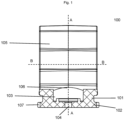
- Figure 1 shows a cross-section of a first element (100) of a bracket system (300) according to a form of implementation of the invention.
- the first element (100) is made of plastic.
- the first element (100) can be made of ferrous or non-ferrous metal.
- the bracket system (300) can be used either inside or outside a building, with the choice of material for the bracket system (300) adapted accordingly.
- use of a plastic bracket system (300) increases the piping system's lifespan.
- the first element (100) comprises a flange (102) and optionally a bracket (105).
- the flange (102) of the first element (100) is circular in shape. Alternatively, as shown in Fig.
- the flange (102) is rectangular or square in shape.
- the flange (102) comprises an opening (104) that is centred in relation to the axis (A) (central axis) of the first element (100).
- the bracket (105) is U-shaped or shaped like an open semi-circle.
- the bracket (105) is configured to fix a pipe securely in drain or water lines, while preferably also giving the pipe room to expand or move in other ways as applicable.
- Plastic brackets allow for rapid installation. Pipes can easily be pressed into place in the bracket (105) without further action. Use of the correct bracket is essential to ensure secure mounting. Failure of the pipe mount can lead to significant damage and high costs. It is therefore important to choose the correct mount.
- the bracket (105) is available in different inner diameters.
- the inner diameter of the bracket (105) is suitable for standard pipe sizes used in plumbing applications, e.g. between 24 mm and 200 mm, for example 25, 32, 40, 50, 56, 63, 75, 80, 90, 100, 110, 125, 150, 160, 180 and 200 mm.
- the bracket (105) comprises an opening (106) that is centred in the first element in relation to the central axis (A).
- this opening (106) is circular in shape.
- the opening (106) in the bracket (105) corresponds to the opening (104) in the flange (102).
- the first element (100) comprises a base (101).
- the base (101) is located between the flange (102) and the bracket (105) in relation to the axis (A) of the first element (100).
- the base (101) of the first element (100) is circular in shape.
- the base (101) is rectangular or square in shape.
- the base (101) comprises an opening (103) that is centred in relation to the axis (A) of the first element (100).
- this opening (103) is circular in shape.
- the opening (103) in the base (101) corresponds to the opening (106) in the bracket (105).
- the base (101), flange (102) and bracket (105) form a single unit.
- the first element (100) comprises two notches (107).
- each notch (107) is shaped like a circular segment so as to centre the first element (100) in relation to latitude axis (B).
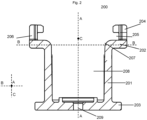
- Figure 2 shows a cross-section of a second element (200) of a bracket system (300) according to a form of implementation of the invention.
- the second element (200) is made of plastic (ferrous or non-ferrous materials).
- the second element (200) comprises a connecting element (202).
- the connecting element (202) of the second element (200) is square in shape.
- the connecting element (202) is rectangular in shape.
- the connecting element (202) is triangular in shape.
- the shape of the connecting element (202) is near-symmetrical in relation to the latitude axis (B) of the second element (200). This symmetry ensures an even distribution of the forces required to hold together the first element (100) and the second element (200), resulting in a stable installation.
- the connecting element (202) comprises an opening (207) that is centred in relation to the axis (A) of the second element (200).
- the axis (A) of the first element (100) coincides with the axis (A) of the second element (200).
- the connecting element (202) comprises two walls (204), where each wall (204) comprises a slot (205) configured to slide over the flange (102) on the first element (100).
- the slot (205) is perpendicular to the surface of the axis (A) of the second element (200) and located on the inside of the wall (204).
- the "inside” here refers to the side closest or proximal to central axis (A).
- the slot (205) has a width equal to the height of the flange (102) on the first element (100).
- two walls (204) of the connecting element (202) are located opposite each other. Alternatively, not shown, two walls (204) of the connecting element (202) form an angle.
- the distance between the two opposite walls (204) of the connecting element (202) narrows in the direction parallel of the axis (B), i.e. the direction along the longitudinal axis (C) and perpendicular to the central axis (A) of the second element (200) in such a way as to ensure a close connection between the flange (102) of the first element (100) and the walls (204) of the connecting element (202).
- the distance between the two opposite walls (204) of the connecting element (202) in a plane parallel to axis (B) narrows in the direction along the longitudinal axis (C) and towards the central axis (A).
- the distance between the opposite walls is larger at a position along longitudinal axis (C) which is more distal with respect to the central axis (A) than another position along said axis (C).
- the walls (204) are funnel-shaped in cross-section in a plane parallel to axis (B) and perpendicular to the axis (A) of the second element (200).
- this perpendicular plane coincides with the axis (C) of the second element (200).
- the term "funnel” or "funnel-shaped” preferably describes a flat cut of a truncated triangle. Preferably, this is an equilateral truncated triangle.
- the funnel height corresponds with the latitude axis (B).
- the term "height" preferably describes a line that passes through a truncated corner point of the funnel and is perpendicular to the opposite side of the truncated triangle, which, in the context of the invention, corresponds to the outside of the wall (204).
- the height of one funnel corresponds to the latitude axis (B) and the height of another funnel corresponds to the longitudinal axis (C).
- the funnel height can be shifted left or right in relation to axis (B) or axis (C), moving the funnel height further away from the angle between the walls (204).
- each of the walls (204) comprises a notch (206).
- the notch (206) is rectangular in shape.
- the width of the notch (206) corresponds to the length of the chord for the notch (107) in the first element (100).
- the height of the notch (206) corresponds to the height of the wall (204).
- the notches (206) are located across, i.e. opposite from each other in the direction of axis (B) of the second element (200), more in particular opposite from each other in the direction of axis (B) and at the height of the central axis (A) of the second element (200).
- the notches (206) are centrally positioned in the opposite walls (204) of the connecting element (202), i.e. the center of the notches coincides with the plane perpendicular to axis (B) and across central axis (A).
- the presence of the notches (206) makes centring the elements (100) and (200) of the bracket system (300) a quick process, as when the notch (107) of the first element (100) is visible through the notch (206) of the second element (200), this means the two elements are centred in relation to each other.
- the notches (206) in the walls also allow for quick disassembly of the elements, making the bracket system (300) suitable for reuse.
- the first element (100) has a rotatable connection or is rotatable connected to the connecting element (202) of the second element (200) around the axis (A).
- rotating the first element (100) allows pipes to be bent in the desired direction.
- the second element (200) comprises a base (201).
- the base (201) of the second element (200) is circular in shape.
- the base (201) is rectangular or square in shape. Drain pipes installed in a plane parallel to the established surface clog more easily. If a drain pipe is positioned at a slope in relation to a horizontal surface such as the floor, the water will flow faster due to the influence of gravity, preventing clogs.
- the bracket system must allow for variations in height, thereby facilitating the flow of water through the piping, reducing the chance of water stagnation and extending the lifespan of the pipes.
- the base (201) can have different heights.
- the height of the base (201) is chosen in such a way that the total height of the second element is between 10 mm and 50 mm, e.g. 10 mm, 20 mm, 30 mm, 40 mm or 50 mm.
- the pipe slope angle can be varied in relation to the surfaces to which the piping system is installed.
- the base (201) comprises an opening (208) that is centred in relation to the axis (A) of the second element (200).
- the opening (208) in the base (201) coincides with an opening (207) in the connecting element (202).
- the second element (200) comprises a flange (203).
- the flange (203) of the second element (200) is circular in shape.
- the flange (102) is rectangular or square in shape.
- the flange (203) comprises an opening (209) that is centred in relation to the axis (A) of the second element (200).
- the opening (209) in the flange (203) coincides with the opening (208) in the base (201).
- the second element (200) comprises two notches (210). Two notches (210) are located across from each other in the direction of the axis C of the second element (200) on the outside of the flange (203).
- each notch (210) is shaped like a circular segment.
- the base (201), flange (203) and connecting element (202) form a single unit.
- the bracket system (300) comprises an additional second element (200).
- the additional second element (200) comprises a connecting element (202), a base (201) and optionally, a flange (203), analogous to the first second element (200) as shown in Figure 2 .
- the flange (203) of the first second element (200) has a rotatable connection to the connecting element (202) of the additional second element (200).
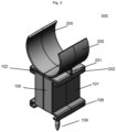
- Fig.3 another form of implementation of a bracket system (300) is illustrated using a perspective view.
- the bracket system (300) comprises a first element (100) and a second element (200).
- the first element (100) comprises a base (101) and a flange (102) and a connecting element (108) similar to the connecting element (202) found on the second element.
- the second element (200) comprises a connecting element (202), a base (201) and a bracket (205), the latter analogous to the bracket (105) of the first element described hereinbefore.
- This implementation differs from the bracket system (300) shown in Fig.
- the base (101) and flange (102) of the first element (100) and the base (201) and flange (203) of the second element (200) are rectangular or square in shape, as shown in Fig.3 , and in that the bracket is now present on the second element instead.
- Fig.4 another form of implementation of a bracket system (300) is illustrated using a perspective view.
- the bracket system (300) comprises a first element (100) and a second element (200).
- This figure shows the narrowing of the distance between the walls (204) of the connecting element (202) in the direction along the longitudinal axis (C) and in the direction of the central axis (A). It further shows the centrally positioned notches (206) in said walls (204).
- On the flange (102) of the first element this figure also shows the notches (107). As explained before, together these notches can be used for centering the two elements with respect to one another.
- the narrowing walls of the connecting element and the circular flange are configured to realize a close-fitting when slid into one another.
- the bracket system (300), as illustrated in Fig. 1-4 can be used as a mounting system for drain lines and optionally, water lines.
Landscapes
- Engineering & Computer Science (AREA)
- General Engineering & Computer Science (AREA)
- Architecture (AREA)
- Civil Engineering (AREA)
- Structural Engineering (AREA)
- Mechanical Engineering (AREA)
- Quick-Acting Or Multi-Walled Pipe Joints (AREA)
- Mutual Connection Of Rods And Tubes (AREA)
- Sink And Installation For Waste Water (AREA)
Claims (15)
- Système de support (300) comprenant au moins un premier élément (100) et un second élément (200), où le second élément (200) comprend un élément de liaison (202) conçu pour se relier à une bride (102) sur le premier élément (100), dans lequel l'élément de liaison (202) comprend deux parois (204), où chaque paroi (204) comprend une fente (205) conçue pour glisser au-dessus de la bride (102) sur le premier élément (100), où la distance entre les deux parois (204) opposées de l'élément de liaison (202) se rétrécit dans la direction perpendiculaire à l'axe central (A) de manière à assurer une liaison étroite entre la bride (102) sur le premier élément (100) et l'élément de liaison (202), caractérisé en ce que chacune des parois (204) comprend une encoche (206), dans lequel les encoches (206) sont de préférence positionnées de manière centrale.
- Système de support (300) selon la revendication 1, où le second élément (200) comprend en outre une base (201) et, éventuellement, une bride (203).
- Système de support (300) selon la revendication 1, où le premier élément (100) comprend en outre une base (101) et éventuellement un élément de liaison (108).
- Système de support (300) selon la revendication 1, moyennant quoi la forme de l'élément de liaison (202) est quasi-symétrique par rapport à l'axe (B) du second élément (200).
- Système de support (300) selon la revendication 1, où l'élément de liaison (202) comprend deux parois (204) opposées, où chaque paroi (204) comprend une fente (205) conçue pour glisser au-dessus de la bride (102) sur le premier élément (100).
- Système de support (300) selon la revendication 5, où les parois (204) ont une section transversale en forme d'entonnoir dans le plan perpendiculaire à l'axe central (A).
- Système de support (300) selon la revendication 2, où la base (201) du second élément (200) est de forme circulaire.
- Système de support (300) selon la revendication 2, où la bride (203) du second élément (200) et/ou la bride (102) du premier élément (100) est de forme circulaire.
- Système de support (300) selon la revendication 3, où la base (101) du premier élément (100) est de forme circulaire.
- Système de support (300) selon l'une des revendications précédentes, où le premier élément (100) a une liaison rotative avec l'élément de liaison (202) du second élément (200) autour de l'axe central (A).
- Système de support (300) selon l'une des revendications précédentes, où la bride (203) a une liaison rotative avec l'élément de liaison (202).
- Système de support (300) selon la revendication 1, où la base (101, 201) comprend une ouverture centrale (103, 208).
- Système de support (300) selon la revendication 1 ou la revendication 2, où la base (102, 203) comprend une ouverture centrale (104, 209).
- Système de support (300) selon l'une des revendications précédentes, où la base (101, 201), la bride (102, 203) et l'élément de liaison (202) forment une seule unité.
- Utilisation du système de support (300) selon les revendications 1 à 14 comme système de montage pour des conduites d'évacuation, des systèmes électriques, des systèmes de collecte de poussière et, éventuellement, des conduites d'eau.
Applications Claiming Priority (2)
| Application Number | Priority Date | Filing Date | Title |
|---|---|---|---|
| BE20215479A BE1028060B1 (nl) | 2021-06-18 | 2021-06-18 | Beugelsysteem |
| PCT/EP2022/065715 WO2022263289A1 (fr) | 2021-06-18 | 2022-06-09 | Système de support |
Publications (4)
| Publication Number | Publication Date |
|---|---|
| EP4356033A1 EP4356033A1 (fr) | 2024-04-24 |
| EP4356033B1 true EP4356033B1 (fr) | 2025-04-09 |
| EP4356033C0 EP4356033C0 (fr) | 2025-04-09 |
| EP4356033B8 EP4356033B8 (fr) | 2025-06-11 |
Family
ID=76695442
Family Applications (1)
| Application Number | Title | Priority Date | Filing Date |
|---|---|---|---|
| EP22732225.2A Active EP4356033B8 (fr) | 2021-06-18 | 2022-06-09 | Système de support |
Country Status (3)
| Country | Link |
|---|---|
| EP (1) | EP4356033B8 (fr) |
| BE (1) | BE1028060B1 (fr) |
| WO (1) | WO2022263289A1 (fr) |
Family Cites Families (6)
| Publication number | Priority date | Publication date | Assignee | Title |
|---|---|---|---|---|
| US3540687A (en) * | 1969-10-31 | 1970-11-17 | Angelo C Cuva | Light socket retainer |
| AT303867B (de) * | 1970-03-05 | 1972-12-11 | Dietzel Gmbh | Befestigungsanordnung für Rohre, insbesondere zur Aufnahme elektrischer Leitungen |
| DE202008000510U1 (de) * | 2008-01-16 | 2008-03-20 | S-Fasteners Gmbh | Kabelhalter-Anordnung |
| US8662455B2 (en) * | 2011-07-14 | 2014-03-04 | Raytheon Company | Spring clip retention systems suitable for usage within vehicles and guided munitions |
| US20180236653A1 (en) * | 2017-02-22 | 2018-08-23 | Jui-Chien Kao | Tool clamping assembly |
| CA3140273A1 (fr) * | 2019-06-24 | 2020-12-30 | Richard Webber | Positionneur de tuyau |
-
2021
- 2021-06-18 BE BE20215479A patent/BE1028060B1/nl active IP Right Grant
-
2022
- 2022-06-09 EP EP22732225.2A patent/EP4356033B8/fr active Active
- 2022-06-09 WO PCT/EP2022/065715 patent/WO2022263289A1/fr not_active Ceased
Also Published As
| Publication number | Publication date |
|---|---|
| BE1028060B1 (nl) | 2023-01-19 |
| EP4356033B8 (fr) | 2025-06-11 |
| WO2022263289A1 (fr) | 2022-12-22 |
| EP4356033A1 (fr) | 2024-04-24 |
| BE1028060A1 (nl) | 2021-09-07 |
| EP4356033C0 (fr) | 2025-04-09 |
Similar Documents
| Publication | Publication Date | Title |
|---|---|---|
| US10508446B2 (en) | Bridge clip | |
| US9022326B2 (en) | Pipe holder and support | |
| US8833013B2 (en) | Termination collar for air duct | |
| US7896296B2 (en) | Offset tube clamp | |
| US10975567B2 (en) | Extendable sleeve for poured concrete deck | |
| EP4118386B1 (fr) | Ensemble raccord de conduit flexible | |
| US9222603B2 (en) | Cord support bracket | |
| US6102341A (en) | Speed clip hanger bracket | |
| WO2019209806A1 (fr) | Tube emboîtable et pince de support de tuyau | |
| US12044428B2 (en) | Quick flex duct connections and system | |
| US20050121559A1 (en) | Simplified pipe support assembly | |
| EP4356033A1 (fr) | Système de support | |
| CA2079719C (fr) | Bride de suspension de tuyau | |
| EP3209889B1 (fr) | Améliorations apportées à des dispositifs de raccordement | |
| JP2019108969A (ja) | 管フランジ識別具及びシステム | |
| US10563401B2 (en) | Bridge clip | |
| US4763867A (en) | Bracket for holding pipe clamps | |
| WO2021163457A1 (fr) | Raccord et ferrule pour raccordement à un conduit flexible | |
| US20190264834A1 (en) | Pipe holder and guide | |
| US20180209147A1 (en) | Rebar Clamp Assembly With Clip | |
| CN211059495U (zh) | 一种可随管路旋转的管夹 | |
| US20220090704A1 (en) | Mid-stream bracket | |
| EP3685083B1 (fr) | Bride d'étanchéité | |
| EP4667795A1 (fr) | Système de support pour tube, tuyau ou conduit | |
| EP4596939A1 (fr) | Raccord à verrouillage par torsion et ensemble pour fixer un tuyau |
Legal Events
| Date | Code | Title | Description |
|---|---|---|---|
| STAA | Information on the status of an ep patent application or granted ep patent |
Free format text: STATUS: UNKNOWN |
|
| STAA | Information on the status of an ep patent application or granted ep patent |
Free format text: STATUS: THE INTERNATIONAL PUBLICATION HAS BEEN MADE |
|
| PUAI | Public reference made under article 153(3) epc to a published international application that has entered the european phase |
Free format text: ORIGINAL CODE: 0009012 |
|
| STAA | Information on the status of an ep patent application or granted ep patent |
Free format text: STATUS: REQUEST FOR EXAMINATION WAS MADE |
|
| 17P | Request for examination filed |
Effective date: 20240118 |
|
| AK | Designated contracting states |
Kind code of ref document: A1 Designated state(s): AL AT BE BG CH CY CZ DE DK EE ES FI FR GB GR HR HU IE IS IT LI LT LU LV MC MK MT NL NO PL PT RO RS SE SI SK SM TR |
|
| DAV | Request for validation of the european patent (deleted) | ||
| DAX | Request for extension of the european patent (deleted) | ||
| GRAP | Despatch of communication of intention to grant a patent |
Free format text: ORIGINAL CODE: EPIDOSNIGR1 |
|
| STAA | Information on the status of an ep patent application or granted ep patent |
Free format text: STATUS: GRANT OF PATENT IS INTENDED |
|
| INTG | Intention to grant announced |
Effective date: 20241115 |
|
| GRAS | Grant fee paid |
Free format text: ORIGINAL CODE: EPIDOSNIGR3 |
|
| GRAA | (expected) grant |
Free format text: ORIGINAL CODE: 0009210 |
|
| STAA | Information on the status of an ep patent application or granted ep patent |
Free format text: STATUS: THE PATENT HAS BEEN GRANTED |
|
| AK | Designated contracting states |
Kind code of ref document: B1 Designated state(s): AL AT BE BG CH CY CZ DE DK EE ES FI FR GB GR HR HU IE IS IT LI LT LU LV MC MK MT NL NO PL PT RO RS SE SI SK SM TR |
|
| REG | Reference to a national code |
Ref country code: GB Ref legal event code: FG4D |
|
| REG | Reference to a national code |
Ref country code: CH Ref legal event code: EP |
|
| REG | Reference to a national code |
Ref country code: DE Ref legal event code: R096 Ref document number: 602022012983 Country of ref document: DE |
|
| REG | Reference to a national code |
Ref country code: IE Ref legal event code: FG4D |
|
| REG | Reference to a national code |
Ref country code: DE Ref legal event code: R081 Ref document number: 602022012983 Country of ref document: DE Owner name: OPDAMO BV, BE Free format text: FORMER OWNER: OPDAMO BV, OPITTER, BE |
|
| REG | Reference to a national code |
Ref country code: CH Ref legal event code: PK Free format text: BERICHTIGUNG B8 |
|
| RAP4 | Party data changed (patent owner data changed or rights of a patent transferred) |
Owner name: OPDAMO BV |
|
| U01 | Request for unitary effect filed |
Effective date: 20250429 |
|
| U07 | Unitary effect registered |
Designated state(s): AT BE BG DE DK EE FI FR IT LT LU LV MT NL PT RO SE SI Effective date: 20250508 |
|
| U20 | Renewal fee for the european patent with unitary effect paid |
Year of fee payment: 4 Effective date: 20250628 |
|
| PG25 | Lapsed in a contracting state [announced via postgrant information from national office to epo] |
Ref country code: ES Free format text: LAPSE BECAUSE OF FAILURE TO SUBMIT A TRANSLATION OF THE DESCRIPTION OR TO PAY THE FEE WITHIN THE PRESCRIBED TIME-LIMIT Effective date: 20250409 |
|
| PG25 | Lapsed in a contracting state [announced via postgrant information from national office to epo] |
Ref country code: GR Free format text: LAPSE BECAUSE OF FAILURE TO SUBMIT A TRANSLATION OF THE DESCRIPTION OR TO PAY THE FEE WITHIN THE PRESCRIBED TIME-LIMIT Effective date: 20250710 Ref country code: NO Free format text: LAPSE BECAUSE OF FAILURE TO SUBMIT A TRANSLATION OF THE DESCRIPTION OR TO PAY THE FEE WITHIN THE PRESCRIBED TIME-LIMIT Effective date: 20250709 |
|
| PG25 | Lapsed in a contracting state [announced via postgrant information from national office to epo] |
Ref country code: PL Free format text: LAPSE BECAUSE OF FAILURE TO SUBMIT A TRANSLATION OF THE DESCRIPTION OR TO PAY THE FEE WITHIN THE PRESCRIBED TIME-LIMIT Effective date: 20250409 |
|
| PG25 | Lapsed in a contracting state [announced via postgrant information from national office to epo] |
Ref country code: HR Free format text: LAPSE BECAUSE OF FAILURE TO SUBMIT A TRANSLATION OF THE DESCRIPTION OR TO PAY THE FEE WITHIN THE PRESCRIBED TIME-LIMIT Effective date: 20250409 |
|
| PG25 | Lapsed in a contracting state [announced via postgrant information from national office to epo] |
Ref country code: RS Free format text: LAPSE BECAUSE OF FAILURE TO SUBMIT A TRANSLATION OF THE DESCRIPTION OR TO PAY THE FEE WITHIN THE PRESCRIBED TIME-LIMIT Effective date: 20250709 |
|
| PG25 | Lapsed in a contracting state [announced via postgrant information from national office to epo] |
Ref country code: IS Free format text: LAPSE BECAUSE OF FAILURE TO SUBMIT A TRANSLATION OF THE DESCRIPTION OR TO PAY THE FEE WITHIN THE PRESCRIBED TIME-LIMIT Effective date: 20250809 |
|
| PG25 | Lapsed in a contracting state [announced via postgrant information from national office to epo] |
Ref country code: SM Free format text: LAPSE BECAUSE OF FAILURE TO SUBMIT A TRANSLATION OF THE DESCRIPTION OR TO PAY THE FEE WITHIN THE PRESCRIBED TIME-LIMIT Effective date: 20250409 |
|
| PG25 | Lapsed in a contracting state [announced via postgrant information from national office to epo] |
Ref country code: CZ Free format text: LAPSE BECAUSE OF FAILURE TO SUBMIT A TRANSLATION OF THE DESCRIPTION OR TO PAY THE FEE WITHIN THE PRESCRIBED TIME-LIMIT Effective date: 20250409 |
|
| PG25 | Lapsed in a contracting state [announced via postgrant information from national office to epo] |
Ref country code: SK Free format text: LAPSE BECAUSE OF FAILURE TO SUBMIT A TRANSLATION OF THE DESCRIPTION OR TO PAY THE FEE WITHIN THE PRESCRIBED TIME-LIMIT Effective date: 20250409 |
|
| REG | Reference to a national code |
Ref country code: CH Ref legal event code: H13 Free format text: ST27 STATUS EVENT CODE: U-0-0-H10-H13 (AS PROVIDED BY THE NATIONAL OFFICE) Effective date: 20260127 |
|
| PG25 | Lapsed in a contracting state [announced via postgrant information from national office to epo] |
Ref country code: MC Free format text: LAPSE BECAUSE OF FAILURE TO SUBMIT A TRANSLATION OF THE DESCRIPTION OR TO PAY THE FEE WITHIN THE PRESCRIBED TIME-LIMIT Effective date: 20250409 |
|
| PLBE | No opposition filed within time limit |
Free format text: ORIGINAL CODE: 0009261 |
|
| STAA | Information on the status of an ep patent application or granted ep patent |
Free format text: STATUS: NO OPPOSITION FILED WITHIN TIME LIMIT |
|
| REG | Reference to a national code |
Ref country code: CH Ref legal event code: L10 Free format text: ST27 STATUS EVENT CODE: U-0-0-L10-L00 (AS PROVIDED BY THE NATIONAL OFFICE) Effective date: 20260218 |
|
| 26N | No opposition filed |
Effective date: 20260112 |
|
| PG25 | Lapsed in a contracting state [announced via postgrant information from national office to epo] |
Ref country code: IE Free format text: LAPSE BECAUSE OF NON-PAYMENT OF DUE FEES Effective date: 20250609 |
|
| PG25 | Lapsed in a contracting state [announced via postgrant information from national office to epo] |
Ref country code: CH Free format text: LAPSE BECAUSE OF NON-PAYMENT OF DUE FEES Effective date: 20250630 |