EP4356742B1 - Nadelregister - Google Patents
Nadelregister Download PDFInfo
- Publication number
- EP4356742B1 EP4356742B1 EP22202919.1A EP22202919A EP4356742B1 EP 4356742 B1 EP4356742 B1 EP 4356742B1 EP 22202919 A EP22202919 A EP 22202919A EP 4356742 B1 EP4356742 B1 EP 4356742B1
- Authority
- EP
- European Patent Office
- Prior art keywords
- needle
- segments
- needles
- distribution chamber
- needle carrier
- Prior art date
- Legal status (The legal status is an assumption and is not a legal conclusion. Google has not performed a legal analysis and makes no representation as to the accuracy of the status listed.)
- Active
Links
Images

Classifications
-
- A—HUMAN NECESSITIES
- A22—BUTCHERING; MEAT TREATMENT; PROCESSING POULTRY OR FISH
- A22C—PROCESSING MEAT, POULTRY, OR FISH
- A22C17/00—Other devices for processing meat or bones
- A22C17/0053—Other devices for processing meat or bones by injection
-
- A—HUMAN NECESSITIES
- A23—FOODS OR FOODSTUFFS; TREATMENT THEREOF, NOT COVERED BY OTHER CLASSES
- A23B—PRESERVATION OF FOODS, FOODSTUFFS OR NON-ALCOHOLIC BEVERAGES; CHEMICAL RIPENING OF FRUIT OR VEGETABLES
- A23B4/00—Preservation of meat, sausages, fish or fish products
- A23B4/26—Apparatus for preserving using liquids ; Processes therefor
- A23B4/28—Apparatus for preserving using liquids ; Processes therefor by injection of liquids
- A23B4/285—Apparatus for preserving using liquids ; Processes therefor by injection of liquids with inorganic salts
Definitions
- the invention relates to a needle register for injection devices for injecting liquid into food products, comprising a needle carrier which forms a distribution chamber for the liquid, a plurality of parallel, hollow needles which are held on the needle carrier in such a way that a section of the needle, which contains a supply opening for supplying the liquid into the needle, lies within the distribution chamber or is at least movable into the distribution chamber.
- one or more needle registers are arranged vertically above a conveyor on which the cured product is advanced step by step. When the conveyor stops, the needle registers are lowered so that the needles pierce the cured product and the brine can be injected.
- a needle register of this type in which several needles are held on a common perforated plate that is removably accommodated in the distribution chamber. Several of these perforated plates are arranged adjacent to one another in the distribution chamber in a tiled pattern. This allows for easy needle replacement.
- the object of the invention is to create a needle register that is easy to clean.
- This object is achieved according to the invention in that the needle carrier is divided into several abutting segments, each of which forms a part of the distribution chamber, and in that the parts of the distribution chamber are flush with one another at the butt joints of the segments.
- the segments of the needle carrier are held firmly together - e.g. in a frame - so that the outer surfaces into which the relevant parts of the distribution chamber open lie tightly against one another, so that the segments together define a continuous distribution chamber in which the brine supplied via an inlet is distributed among the needles held in the segments of the needle carrier.
- the frame is opened and the segments of the needle carrier are separated from one another so that they can be cleaned individually.
- the needles are removed and cleaned separately if necessary.
- the part of the distribution chamber formed by a single segment is then a continuous channel open at both ends with smooth walls, which has no corners that are difficult to clean and thus, for example, can be easily cleaned with a brush pushed through the channel.
- the needles can be held in groups in perforated plates that are releasably mounted in or on the individual segments of the needle carrier, so that all needles located on the same perforated plate can be removed from the respective segment of the needle carrier with a single movement.
- each segment of the needle carrier can also have a removable cover that allows access to the distribution chamber.
- the perforated plates can also be arranged inside the distribution chamber.
- the perforated plates are located outside the distribution chamber, they can be arranged in such a way that, in the position of use, they abut one another in the same way as the segments of the needle carrier and that the needles are arranged in a uniform grid across the boundaries of the segments.
- outlets of the distribution chamber segments can be surrounded by a seal that reliably prevents brine from escaping at the joints between the individual segments.
- these outlets can be designed as complementary connectors that ensure the various parts of the distribution chamber fit flush with one another.
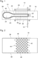
- Fig. 1 a single segment 10 of a needle carrier 12 is shown.
- the needle carrier 12 is part of a needle register 14, which is completely Fig. 3 shown and which is used, for example, in a pickle injector to inject brine into pieces of meat.
- Attached to each segment 10 of the needle carrier 12 are several hollow needles 16 which extend vertically downwards from the needle carrier. Fig. 1 For the sake of simplicity, only one of these needles 16 is shown.
- the needle register 14 is arranged vertically movable above a conveyor (not shown), on which the pieces of meat are fed.
- the needle carrier is lowered, the needles 16 pierce the meat, allowing the cure layer to be injected.
- Each segment 10 of the needle carrier 12 is formed mainly by a block 18 made of a food-grade plastic, in which a Fig. 1 continuous channel 20 is cut out.
- the distribution chamber 22 on the left side in Fig. 1 a supply channel 24, which extends over the entire length of the distribution chamber and has a larger cross-section than the rest of the distribution chamber.
- This supply channel 24 is connected to the right in Fig. 1 a flatter section 26 of the distribution chamber.
- the needles 16 extend in the area of the section 26 of the distribution chamber through bores 42 ( Fig. 2 ) of the block 18 and are fastened with their upper ends outside the block 18 in holes of a perforated plate 28 which is releasably fixed to the block 18 and is supported on the upper side of the block 18 via supports 30.
- Each needle 16 has a section 32 which extends vertically through the interior of the distribution chamber 22. This section 32 contains at least one feed opening 34 through which brine can flow from the distribution chamber into the interior of the hollow needles.
- a further perforated metal plate 36 is attached to the underside of block 18, providing stable guidance for the needles 16.
- each needle 16 is sealed with seals (not shown) to prevent brine from escaping through these bores.
- a slightly raised plateau 38 is formed, in which the mouth of channel 20 is located and whose edge follows the course of the wall of this channel.
- a groove 40 is formed in the end face of this plateau, which groove 40 runs around channel 20 and accommodates a seal for sealing the joint between adjacent segments 10 of needle carrier 12.
- a corresponding plateau and groove are also formed on the opposite end face of block 18, so that the aforementioned seal engages the grooves 40 of both abutting segments 10.
- Fig. 2 block 18 is shown in plan view, so that the plateaus 38 are visible on both faces of the block.
- the openings of the bores 42 which accommodate the needles 16 and form a regular grid.
- Mounting holes 44 for the perforated plate 28 are also visible.
- the two opposite end faces of the block 18 outside the plateaus 38 each have a wave profile 46 and 48, respectively.
- These wave profiles 46, 48 are complementary to one another, so that the wave profiles of two adjacent segments 10 interlock and hold the segments in a relative position in which the channels 20 forming the distribution chamber 22 are flush with one another.
- these wave profiles 46, 48 make it possible to arrange the bores 42 so close to the end faces of the block 18 that the grid of these bores 42 continues beyond the butt joint between the segments 10 in the adjacent segment.
- Fig. 3 The complete needle register 14 is shown in a top view, the needle carrier 12 of which is formed in this example by three segments 10 arranged next to one another.
- Fig. 3 not shown needles 16, the perforated plates 28 have holes 50 which are arranged in the same grid as the holes 42 in Fig. 2
- the perforated plates 28 also have interlocking wave profiles on their edges, which correspond to the wave profiles 46, 48.
- the front surface of the Fig. 3 uppermost segment 10 connects with its projection 38 to a nozzle 52 of a connection block 54, via which the brine supplied via an inlet 56 is fed under pressure into the distribution chamber 22.
- the Fig. 3 The lowermost segment 10 connects with its projection 38 to an end plate 58.
- the connecting block 54 and the end plate 58 are held between two frame elements 60, which are releasably connected to one another by tension bolts 62 and can be clamped against one another, so that the connecting block 54, the segments 10, and the end plate 58 are firmly held together.
- the frame elements 60 each have two guide eyes 64, with which the needle register 64 is guided for vertical movement on guide rods (not shown).
- the segments 10 of the needle carrier 12 can be separated from one another, and after removing the perforated plates 28 equipped with the needles 16, the through channels 20 of the individual segments can be cleaned easily and thoroughly.
- the invention is also applicable to needle registers with spring-loaded needles, in which the needles are movable relative to the needle carrier so that they can deflect when hitting bone, for example.
Landscapes
- Life Sciences & Earth Sciences (AREA)
- Engineering & Computer Science (AREA)
- Chemical & Material Sciences (AREA)
- Wood Science & Technology (AREA)
- Zoology (AREA)
- Food Science & Technology (AREA)
- Inorganic Chemistry (AREA)
- Polymers & Plastics (AREA)
- Meat, Egg Or Seafood Products (AREA)
- Processing Of Meat And Fish (AREA)
Description
- Die Erfindung betrifft ein Nadelregister für Injektionsvorrichtungen zur Injektion von Flüssigkeit in Lebensmittelprodukte, mit einem Nadelträger, der eine Verteilerkammer für die Flüssigkeit bildet, mehreren parallelen, hohlen Nadeln, die so an dem Nadelträger gehalten sind, dass jeweils ein Abschnitt der Nadel, der eine Zufuhröffnung für die Zufuhr der Flüssigkeit in die Nadel enthält, innerhalb der Verteilerkammer liegt oder zumindest in die Verteilerkammer bewegbar ist.
- Beispiele für Injektionsvorrichtungen, in denen solche Nadelregister verwendet werden, sind etwa Pökelvorrichtungen, mit denen Lake in Fleischprodukte injiziert wird. Typischerweise sind ein oder mehrere Nadelregister vertikalbeweglich über einem Förderer angeordnet, auf dem das Pökelgut schrittweise vorgerückt wird. Wenn der Förderer anhält, werden die Nadelregister abgesenkt, so dass die Nadeln in das Pökelgut einstechen und die Lake injiziert werden kann.
- Aus
EP 3 449 731 A1 ist ein Nadelregister dieser Art bekannt, bei dem jeweils mehrere Nadeln an einer geneinsamen Lochplatte gehalten sind, die entnehmbar in der Verteilerkammer aufgenommen ist. Mehrere dieser Lochplatten sind nach Art eines Kachelmusters aneinandergrenzend in der Verteilerkammer angeordnet. Dadurch wird ein einfaches Auswechseln der Nadeln ermöglicht. - Da die Flüssigkeiten, die in die Lebensmittelprodukte injiziert werden, mit den Innenflächen der Nadeln und der Verteilerkammer in Berührung kommen, ist eine regelmäßige und gründliche Reinigung des Nadelregisters unerlässlich.
- Aufgabe der Erfindung ist es, ein reinigungsfreundliches Nadelregister zu schaffen. Diese Aufgabe wird erfindungsgemäß dadurch gelöst, dass der Nadelträger in mehrere auf Stoß aneinandergrenzende Segmente unterteilt ist, die jeweils einen Teil der Verteilerkammer bilden, und dass die Teile der Verteilerkammer an den Stoßfugen der Segmente bündig aneinander anschließen.
- Im betriebsbereiten Zustand der Pökelvorrichtung sind die Segmente des Nadelträgers - z.B. in einem Rahmen - fest zusammengehalten, so dass die Außenflächen, in denen die betreffenden Teile der Verteilerkammer münden, dicht aneinander anliegen, so dass die Segmente zusammen eine durchgehende Verteilerkammer begrenzen, in der die über einen Zulauf zugeführte Pökellake auf die in den Segmenten des Nadelträgers gehaltenen Nadeln verteilt wird. Wenn das Nadelregister gereinigt werden soll, so wird der Rahmen geöffnet, und die Segmente des Nadelträgers werden voneinander getrennt, so dass sie einzeln gereinigt werden können. Dazu werden die Nadeln entfernt und gegebenenfalls separat gereinigt. Der Teil der Verteilerkammer, der durch ein einzelnes Segment gebildet wird, ist dann ein an beiden Enden offener durchgehender Kanal mit glatten Wänden, der keine schwer zu reinigenden Ecken aufweist und somit beispielsweise mit einer durch den Kanal hindurchgesteckten Bürste einfach gereinigt werden kann.
- Vorteilhafte Ausgestaltungen der Erfindung sind in den Unteransprüchen angegeben. Die Nadeln können gruppenweise in Lochplatten gehalten sein, die lösbar in oder an den einzelnen Segmenten des Nadelträgers gehalten sind, so dass sich die alle Nadeln, die sich an derselben Lochplatte befinden, mit einem einzigen Handgriff aus dem betreffenden Segment des Nadelträgers herausziehen lassen.
- Wahlweise kann jedes Segment des Nadelträgers auch einen lösbaren Deckel aufweisen, der einen Zugang zu der Verteilerkammer ermöglicht. In dem Fall können die Lochplatten auch im Inneren der Verteilerkammer angeordnet sein.
- Wenn die Lochplatten außerhalb der Verteilerkammer liegen, können sie so angeordnet sein, dass sie in der Gebrauchsstellung ebenso wie die Segmente des Nadelträgers auf Stoß aneinander anliegen und dass die Nadeln über die Grenzen der Segmente hinweg in einem einheitlichen Raster angeordnet sind.
- Die Mündungen der Segmente der Verteilerkammer können von einer Dichtung umgeben sein, die den Austritt von Lake an den Stoßfugen zwischen den einzelnen Segmenten sicher verhindert. Wahlweise können diese Mündungen als komplementäre Steckverbinder gestaltet sein, die sicherstellen, dass die verschiedenen Teile der Verteilerkammer bündig aneinander anschließen.
- Im folgenden wird ein Ausführungsbeispiel anhand der Zeichnung näher erläutert.
- Es zeigen:
- Fig. 1
- ein Segment eines Nadelträgers eines erfindungsgemäßen Nadelregisters in einer Stirnansicht;
- Fig. 2
- das Segment nach
Fig. 1 in der Draufsicht; und - Fig. 3
- das komplette Nadelregister in der Draufsicht.
- In
Fig. 1 ist ein einzelnes Segment 10 eines Nadelträgers 12 dargestellt. Der Nadelträger 12 ist Teil eines Nadelregisters 14, das vollständig inFig. 3 gezeigt ist und das beispielsweise in einem Pökelinjektor dazu dient, Pökellake in Fleischstücke zu injizieren. An jedem Segment 10 des Nadelträgers 12 sind mehrere hohle Nadeln 16 befestigt, die sich von dem Nadelträger aus senkrecht nach unten erstrecken. InFig. 1 ist der Einfachheit halber nur eine dieser Nadeln 16 gezeigt. - In dem Pökelinjektor ist das Nadelregister 14 vertikalbeweglich über einem nicht gezeigten Förderer angeordnet, auf dem die Fleischstücke zugeführt werden. Wenn der Nadelträger abgesenkt wird, stechen die Nadeln 16 in das Fleisch ein, so dass die Pökellage injiziert werden kann.
- Jedes Segment 10 des Nadelträgers 12 wird in der Hauptsache durch einen Block 18 aus einem lebensmittelverträglichen Kunststoff gebildet, in dem ein in der Richtung senkrecht zur Zeichenebene in
Fig. 1 durchgehender Kanal 20 ausgespart ist. Dieser Kanal 20 bildet zusammen mit entsprechenden Kanälen weiterer Segmente 10 des Nadelträgers 12 eine durchgehende Verteilerkammer 22, die den größten Teil der Grundfläche des Nadelträgers 12 einnimmt. Im gezeigten Beispiel bildet die Verteilerkammer 22 auf der linken Seite inFig. 1 einen Zufuhrkanal 24, der sich über die gesamte Länge der Verteilerkammer erstreckt und einen gegenüber dem Rest der Verteilerkammer vergrößerten Querschnitt aufweist. An diesen Zufuhrkanal 24 schließt sich nach rechts inFig. 1 ein flacherer Abschnitt 26 der Verteilerkammer an. - Die Nadeln 16 erstrecken sich im Bereich des Abschnitts 26 der Verteilerkammer durch Bohrungen 42 (
Fig. 2 ) des Blockes 18 und sind mit ihren oberen Enden außerhalb des Blockes 18 in Löchern einer Lochplatte 28 befestigt, die lösbar an dem Block 18 fixiert ist und sich über Stützen 30 auf der Oberseite des Blockes 18 abstützt. Jede Nadel 16 weist einen Abschnitt 32 auf, der vertikal durch das Innere der Verteilerkammer 22 verläuft. In diesem Abschnitt 32 befindet sich mindestens eine Zufuhröffnung 34, über die Pökellage aus der Verteilerkammer in das Innere der Hohlnadeln gelangen kann. An der Unterseite des Blockes 18 ist eine weitere Lochplatte 36 aus Metall befestigt, die den Nadeln 16 stabile Führung gibt. In den Bohrungen des Blockes 18 oberhalb und unterhalb des Abschnittes 26 der Verteilerkammer ist jede Nadel 16 mit nicht gezeigten Dichtungen gegenüber der Bohrung abgedichtet, so dass der Austritt von Lake durch diese Bohrungen verhindert wird. - Auf der in
Fig. 1 sichtbaren Stirnfläche des Blockes 18 ist ein leicht erhabenes Plateau 38 gebildet, in dem sich die Mündung des Kanals 20 befindet und dessen Rand dem Verlauf der Wand dieses Kanals folgt. In der Stirnfläche dieses Plateaus ist eine um den Kanal 20 umlaufende Nut 40 gebildet, die eine Dichtung zur Abdichtung der Fuge zwischen aneinander angrenzenden Segmenten 10 des Nadelträgers 12 aufnimmt. Ein entsprechendes Plateau und eine entsprechende Nut sind auch auf der entgegengesetzten Stirnfläche des Blockes 18 gebildet, so dass die erwähnte Dichtung in die Nuten 40 beider auf Stoß aneinanderliegender Segmente 10 eingreift. - In
Fig. 2 ist der Block 18 in der Draufsicht gezeigt, so dass die Plateaus 38 an beiden Stirnflächen des Blockes sichtbar sind. Außerdem sieht man inFig. 2 die Mündungen der Bohrungen 42, die die Nadeln 16 aufnehmen und die ein regelmäßiges Raster bilden. Ebenso sind Befestigungslöcher 44 für die Lochplatte 28 erkennbar. Im Bereich der Lochplatte 28 haben die beiden entgegengesetzten Stirnflächen des Blockes 18 außerhalb der Plateaus 38 jeweils ein Wellenprofil 46 bzw. 48. Diese Wellenprofile 46,48 sind zueinander komplementär, so dass die Wellenprofile zweier benachbarter Segmente 10 ineinandergreifen und die Segmente in einer Relativposition halten, in der die Kanäle 20, die die Verteilerkammer 22 bilden, miteinander bündig sind. Zugleich ermöglichen es diese Wellenprofile 46, 48, die Bohrungen 42 so dicht an den Stirnflächen des Blockes 18 anzuordnen, dass sich das Raster dieser Bohrungen 42 über die Stoßfuge zwischen den Segmenten 10 hinweg im benachbarten Segment fortsetzt. - In
Fig. 3 ist in einer Draufsicht das komplette Nadelregister 14 gezeigt, dessen Nadelträger 12 in diesem Bespiel durch drei aneinandergereihte Segmente 10 gebildet wird. Zur Aufnahme der inFig. 3 nicht gezeigten Nadeln 16 weisen die Lochplatten 28 Löcher 50 auf, die im gleichen Raster angeordnet sind wie die Bohrungen 42 inFig. 2 . Auch die Lochplatten 28 haben an ihren Rändern ineinandergreifende Wellenprofile, die den Wellenprofilen 46, 48 entsprechen. Die Stirnfläche des inFig. 3 obersten Segments 10 schließt mit ihrem Vorsprung 38 an einen Stutzen 52 eines Anschlussblockes 54 an, über den die über einen Zulauf 56 zugeführte Lake unter Druck in die Verteilerkammer 22 zugeführt wird. Das inFig. 3 unterste Segment 10 schließt mit seinem Vorsprung 38 an eine Abschlussplatte 58 an. Der Anschlussblock 54 und die Abschlussplatte 58 sind zwischen zwei Rahmenelementen 60 gehalten, die durch Zugbolzen 62 lösbar miteinander verbunden und gegeneinander spannbar sind, so dass der Anschlussblock 54, die Segmente 10 und die Abschlussplatte 58 fest zusammengehalten werden. Außenseitig weisen die Rahmenelemente 60 jeweils zwei Führungsaugen 64 auf, mit denen das Nadelregister 64 vertikalbeweglich an nicht gezeigten Führungsstangen geführt ist. - Wenn die Zugbolzen 62 gelöst werden, lassen sich die Segmente 10 des Nadelträgers 12 voneinander trennen, und nach Entfernen der mit den Nadeln 16 bestückten Lochplatten 28 können die durchgehenden Kanäle 20 der einzelnen Segmente einfach und gründlich gereinigt werden.
- Während im gezeigten Beispiel die Nadeln 16 starr am Nadelträger 12 gehalten sind, ist die Erfindung auch bei Nadelregistern mit gefederten Nadeln anwendbar, bei denen die Nadeln relativ zum Nadelträger beweglich sind, so dass sie beispielsweise beim Auftreffen auf Knochen ausweichen können.
Claims (8)
- Nadelregister für Injektionsvorrichtungen zur Injektion von Flüssigkeit in Lebensmittelprodukte, mit einem Nadelträger (12), der eine Verteilerkammer (22) für die Flüssigkeit bildet, mehreren parallelen, hohlen Nadeln (16), die so an dem Nadelträger (12) gehalten sind, dass jeweils ein Abschnitt (32) der Nadel, der eine Zufuhröffnung (34) für die Zufuhr der Flüssigkeit in die Nadel enthält, innerhalb der Verteilerkammer (22) liegt oder zumindest in die Verteilerkammer bewegbar ist, dadurch gekennzeichnet, dass der Nadelträger in mehrere auf Stoß aneinandergrenzende Segmente (10) unterteilt ist, die jeweils einen Teil (12) der Verteilerkammer (22) bilden, und dass die Teile der Verteilerkammer (22) an den Stoßfugen der Segmente (10) bündig aneinander anschließen.
- Nadelregister nach Anspruch 1, bei dem die Segmente (10) des Nadelträgers (12) in einer Reihe angeordnet sind.
- Nadelträger nach Anspruch 2, bei dem die Segmente (10) so gegeneinander spannbar sind, dass ihre aneinander anliegenden Stirnflächen fest gegeneinander angedrückt werden.
- Nadelregister nach Anspruch 2 oder 3, bei dem die Verteilerkammer (21) einen von den Nadeln (16) durchlaufenden Abschnitt (26) und einen daran anschließenden, sich über sämtliche Segmente (10) erstreckenden Zufuhrkanal (24) mit erweitertem Querschnitt aufweist.
- Nadelregister nach einem der vorstehenden Ansprüche, bei dem die zwischen den Segmenten (10) gebildeten Stoßfugen jeweils mit einer die Verteilerkammer (22) umgebenden Dichtung (40) abgedichtet sind.
- Nadelregister nach einem der vorstehenden Ansprüche, bei dem die Nadeln (16) in einem über die Grenzen der Segmente (10) einheitlichen Raster angeordnet sind.
- Nadelregister nach einem der vorstehenden Ansprüche, bei dem jeweils mehrere Nadeln (16) starr an einer gemeinsamen Lochplatte (28) angeordnet sind, die lösbar an einem der Segmente (10) des Nadelträgers (12) gehalten ist.
- Nadelträger nach Anspruch 6, bei dem die aneinander anliegenden Stirnflächen der Segmente (10) zueinander komplementäre Wellenprofile (46, 48) aufweisen, die parallel zu den Nadeln (16) verlaufen.
Priority Applications (3)
| Application Number | Priority Date | Filing Date | Title |
|---|---|---|---|
| EP22202919.1A EP4356742B1 (de) | 2022-10-21 | 2022-10-21 | Nadelregister |
| ES22202919T ES3037851T3 (en) | 2022-10-21 | 2022-10-21 | Needle register |
| DK22202919.1T DK4356742T3 (da) | 2022-10-21 | 2022-10-21 | Nåleregister |
Applications Claiming Priority (1)
| Application Number | Priority Date | Filing Date | Title |
|---|---|---|---|
| EP22202919.1A EP4356742B1 (de) | 2022-10-21 | 2022-10-21 | Nadelregister |
Publications (2)
| Publication Number | Publication Date |
|---|---|
| EP4356742A1 EP4356742A1 (de) | 2024-04-24 |
| EP4356742B1 true EP4356742B1 (de) | 2025-05-07 |
Family
ID=83903100
Family Applications (1)
| Application Number | Title | Priority Date | Filing Date |
|---|---|---|---|
| EP22202919.1A Active EP4356742B1 (de) | 2022-10-21 | 2022-10-21 | Nadelregister |
Country Status (3)
| Country | Link |
|---|---|
| EP (1) | EP4356742B1 (de) |
| DK (1) | DK4356742T3 (de) |
| ES (1) | ES3037851T3 (de) |
Family Cites Families (4)
| Publication number | Priority date | Publication date | Assignee | Title |
|---|---|---|---|---|
| US6658990B1 (en) * | 2000-11-27 | 2003-12-09 | Mepsco, Inc. | Bushing construction for a fluid injection machine in a food processing system |
| DE202011050701U1 (de) * | 2011-07-12 | 2012-10-23 | Schröder Maschinenbau KG | Nadelregister |
| IT201700097347A1 (it) | 2017-08-30 | 2019-03-02 | Bravo Spa | Mantecatore a bloccaggio e apertura rapidi e sicuri |
| EP3449731A1 (de) * | 2017-09-04 | 2019-03-06 | Schröder Maschinenbau GmbH & Co. KG | Nadelregister |
-
2022
- 2022-10-21 DK DK22202919.1T patent/DK4356742T3/da active
- 2022-10-21 EP EP22202919.1A patent/EP4356742B1/de active Active
- 2022-10-21 ES ES22202919T patent/ES3037851T3/es active Active
Also Published As
| Publication number | Publication date |
|---|---|
| EP4356742A1 (de) | 2024-04-24 |
| DK4356742T3 (da) | 2025-08-18 |
| ES3037851T3 (en) | 2025-10-07 |
Similar Documents
| Publication | Publication Date | Title |
|---|---|---|
| DE2219403A1 (de) | Druckvorrichtung | |
| DE3727843A1 (de) | Vorrichtung zum ausstossen von fluessigkeitsstrahlen hoher geschwindigkeit auf faserfoermige materialien | |
| DE1729136A1 (de) | Siebauswechselvorrichtung | |
| DE102015102817A1 (de) | Vorrichtung zum Abscheiden und Entfernen von Siebgut aus einer mit Siebgut verunreinigten strömenden Flüssigkeit | |
| EP0603647B1 (de) | Vorrichtung zum kontinuierlichen Herstellen von Schaumstoffbahnen, insbesondere Hartschaumstoffplatten | |
| EP0626141A1 (de) | Verfahren zum Konfigurieren von Borstenbündeln | |
| EP4356742A1 (de) | Nadelregister | |
| EP1309403B1 (de) | Schaltblock mit mindestens einem daran angebrachten oder integrierten reaktionsgefäss | |
| EP2545782B1 (de) | Nadelregister | |
| DE2808951A1 (de) | Einspritzduese fuer eine kunststoff- spritzgussmaschine | |
| EP4194112B1 (de) | Spritzvorrichtung und verfahren zur innenspritzung von behältern | |
| EP3449731A1 (de) | Nadelregister | |
| DE102011051737B4 (de) | Verfahren und Vorrichtung zum partiellen Abtragen einer Beschichtung | |
| DE4235523C1 (de) | Siebvorrichtung für Kunststoffschmelzen | |
| EP1468747B1 (de) | Sprühkopf für ein Sprühwerkzeug | |
| DE10348788B3 (de) | Vorrichtung zum Auftragen von Flüssigkeiten auf eine laufende Bahn | |
| DE19530045C1 (de) | Nadelregister für Pökelmaschinen | |
| DE2522825B1 (de) | Schiesskopf einer schiessmaschine fuer giessereizwecke zum fuellen von form- oder kernkaesten | |
| DE2114764A1 (de) | Filterpresse | |
| DE10214466A1 (de) | Spritzgießmaschine | |
| DE202005012005U1 (de) | Vorrichtung zur Bearbeitung von Lebensmitteln | |
| DE19530046C2 (de) | Schnellreinigungs-Nadelregister für Pökelmaschinen | |
| DE4117196C2 (de) | Handhobel mit Gestell | |
| DE2652849A1 (de) | Verfahren zur durchfuehrung von mischvorgaengen o.dgl. sowie vorrichtung zur durchfuehrung des verfahrens | |
| DE4008636A1 (de) | Spritzstation |
Legal Events
| Date | Code | Title | Description |
|---|---|---|---|
| PUAI | Public reference made under article 153(3) epc to a published international application that has entered the european phase |
Free format text: ORIGINAL CODE: 0009012 |
|
| STAA | Information on the status of an ep patent application or granted ep patent |
Free format text: STATUS: THE APPLICATION HAS BEEN PUBLISHED |
|
| AK | Designated contracting states |
Kind code of ref document: A1 Designated state(s): AL AT BE BG CH CY CZ DE DK EE ES FI FR GB GR HR HU IE IS IT LI LT LU LV MC ME MK MT NL NO PL PT RO RS SE SI SK SM TR |
|
| STAA | Information on the status of an ep patent application or granted ep patent |
Free format text: STATUS: REQUEST FOR EXAMINATION WAS MADE |
|
| 17P | Request for examination filed |
Effective date: 20241017 |
|
| RBV | Designated contracting states (corrected) |
Designated state(s): AL AT BE BG CH CY CZ DE DK EE ES FI FR GB GR HR HU IE IS IT LI LT LU LV MC ME MK MT NL NO PL PT RO RS SE SI SK SM TR |
|
| GRAP | Despatch of communication of intention to grant a patent |
Free format text: ORIGINAL CODE: EPIDOSNIGR1 |
|
| STAA | Information on the status of an ep patent application or granted ep patent |
Free format text: STATUS: GRANT OF PATENT IS INTENDED |
|
| INTG | Intention to grant announced |
Effective date: 20241204 |
|
| GRAS | Grant fee paid |
Free format text: ORIGINAL CODE: EPIDOSNIGR3 |
|
| GRAA | (expected) grant |
Free format text: ORIGINAL CODE: 0009210 |
|
| STAA | Information on the status of an ep patent application or granted ep patent |
Free format text: STATUS: THE PATENT HAS BEEN GRANTED |
|
| AK | Designated contracting states |
Kind code of ref document: B1 Designated state(s): AL AT BE BG CH CY CZ DE DK EE ES FI FR GB GR HR HU IE IS IT LI LT LU LV MC ME MK MT NL NO PL PT RO RS SE SI SK SM TR |
|
| REG | Reference to a national code |
Ref country code: GB Ref legal event code: FG4D Free format text: NOT ENGLISH |
|
| REG | Reference to a national code |
Ref country code: CH Ref legal event code: EP |
|
| REG | Reference to a national code |
Ref country code: DE Ref legal event code: R096 Ref document number: 502022003852 Country of ref document: DE |
|
| REG | Reference to a national code |
Ref country code: IE Ref legal event code: FG4D Free format text: LANGUAGE OF EP DOCUMENT: GERMAN |
|
| REG | Reference to a national code |
Ref country code: DK Ref legal event code: T3 Effective date: 20250808 |
|
| REG | Reference to a national code |
Ref country code: NL Ref legal event code: FP |
|
| REG | Reference to a national code |
Ref country code: ES Ref legal event code: FG2A Ref document number: 3037851 Country of ref document: ES Kind code of ref document: T3 Effective date: 20251007 |
|
| PG25 | Lapsed in a contracting state [announced via postgrant information from national office to epo] |
Ref country code: PT Free format text: LAPSE BECAUSE OF FAILURE TO SUBMIT A TRANSLATION OF THE DESCRIPTION OR TO PAY THE FEE WITHIN THE PRESCRIBED TIME-LIMIT Effective date: 20250908 Ref country code: FI Free format text: LAPSE BECAUSE OF FAILURE TO SUBMIT A TRANSLATION OF THE DESCRIPTION OR TO PAY THE FEE WITHIN THE PRESCRIBED TIME-LIMIT Effective date: 20250507 |
|
| REG | Reference to a national code |
Ref country code: LT Ref legal event code: MG9D |
|
| PG25 | Lapsed in a contracting state [announced via postgrant information from national office to epo] |
Ref country code: NO Free format text: LAPSE BECAUSE OF FAILURE TO SUBMIT A TRANSLATION OF THE DESCRIPTION OR TO PAY THE FEE WITHIN THE PRESCRIBED TIME-LIMIT Effective date: 20250807 Ref country code: GR Free format text: LAPSE BECAUSE OF FAILURE TO SUBMIT A TRANSLATION OF THE DESCRIPTION OR TO PAY THE FEE WITHIN THE PRESCRIBED TIME-LIMIT Effective date: 20250808 |
|
| PG25 | Lapsed in a contracting state [announced via postgrant information from national office to epo] |
Ref country code: PL Free format text: LAPSE BECAUSE OF FAILURE TO SUBMIT A TRANSLATION OF THE DESCRIPTION OR TO PAY THE FEE WITHIN THE PRESCRIBED TIME-LIMIT Effective date: 20250507 |
|
| PGFP | Annual fee paid to national office [announced via postgrant information from national office to epo] |
Ref country code: NL Payment date: 20250924 Year of fee payment: 4 |
|
| PG25 | Lapsed in a contracting state [announced via postgrant information from national office to epo] |
Ref country code: BG Free format text: LAPSE BECAUSE OF FAILURE TO SUBMIT A TRANSLATION OF THE DESCRIPTION OR TO PAY THE FEE WITHIN THE PRESCRIBED TIME-LIMIT Effective date: 20250507 |
|
| PG25 | Lapsed in a contracting state [announced via postgrant information from national office to epo] |
Ref country code: HR Free format text: LAPSE BECAUSE OF FAILURE TO SUBMIT A TRANSLATION OF THE DESCRIPTION OR TO PAY THE FEE WITHIN THE PRESCRIBED TIME-LIMIT Effective date: 20250507 |
|
| PGFP | Annual fee paid to national office [announced via postgrant information from national office to epo] |
Ref country code: FR Payment date: 20250922 Year of fee payment: 4 |
|
| PG25 | Lapsed in a contracting state [announced via postgrant information from national office to epo] |
Ref country code: RS Free format text: LAPSE BECAUSE OF FAILURE TO SUBMIT A TRANSLATION OF THE DESCRIPTION OR TO PAY THE FEE WITHIN THE PRESCRIBED TIME-LIMIT Effective date: 20250807 |
|
| PG25 | Lapsed in a contracting state [announced via postgrant information from national office to epo] |
Ref country code: IS Free format text: LAPSE BECAUSE OF FAILURE TO SUBMIT A TRANSLATION OF THE DESCRIPTION OR TO PAY THE FEE WITHIN THE PRESCRIBED TIME-LIMIT Effective date: 20250907 |
|
| PG25 | Lapsed in a contracting state [announced via postgrant information from national office to epo] |
Ref country code: LV Free format text: LAPSE BECAUSE OF FAILURE TO SUBMIT A TRANSLATION OF THE DESCRIPTION OR TO PAY THE FEE WITHIN THE PRESCRIBED TIME-LIMIT Effective date: 20250507 |
|
| PGFP | Annual fee paid to national office [announced via postgrant information from national office to epo] |
Ref country code: DE Payment date: 20250916 Year of fee payment: 4 |
|
| PG25 | Lapsed in a contracting state [announced via postgrant information from national office to epo] |
Ref country code: SM Free format text: LAPSE BECAUSE OF FAILURE TO SUBMIT A TRANSLATION OF THE DESCRIPTION OR TO PAY THE FEE WITHIN THE PRESCRIBED TIME-LIMIT Effective date: 20250507 |
|
| PGFP | Annual fee paid to national office [announced via postgrant information from national office to epo] |
Ref country code: AT Payment date: 20260113 Year of fee payment: 4 |
|
| PGFP | Annual fee paid to national office [announced via postgrant information from national office to epo] |
Ref country code: DK Payment date: 20251014 Year of fee payment: 4 |
|
| PG25 | Lapsed in a contracting state [announced via postgrant information from national office to epo] |
Ref country code: CZ Free format text: LAPSE BECAUSE OF FAILURE TO SUBMIT A TRANSLATION OF THE DESCRIPTION OR TO PAY THE FEE WITHIN THE PRESCRIBED TIME-LIMIT Effective date: 20250507 |
|
| PG25 | Lapsed in a contracting state [announced via postgrant information from national office to epo] |
Ref country code: EE Free format text: LAPSE BECAUSE OF FAILURE TO SUBMIT A TRANSLATION OF THE DESCRIPTION OR TO PAY THE FEE WITHIN THE PRESCRIBED TIME-LIMIT Effective date: 20250507 |
|
| PG25 | Lapsed in a contracting state [announced via postgrant information from national office to epo] |
Ref country code: SK Free format text: LAPSE BECAUSE OF FAILURE TO SUBMIT A TRANSLATION OF THE DESCRIPTION OR TO PAY THE FEE WITHIN THE PRESCRIBED TIME-LIMIT Effective date: 20250507 |
|
| PG25 | Lapsed in a contracting state [announced via postgrant information from national office to epo] |
Ref country code: IT Free format text: LAPSE BECAUSE OF FAILURE TO SUBMIT A TRANSLATION OF THE DESCRIPTION OR TO PAY THE FEE WITHIN THE PRESCRIBED TIME-LIMIT Effective date: 20250507 |
|
| PGFP | Annual fee paid to national office [announced via postgrant information from national office to epo] |
Ref country code: ES Payment date: 20251105 Year of fee payment: 4 |
|
| REG | Reference to a national code |
Ref country code: DE Ref legal event code: R097 Ref document number: 502022003852 Country of ref document: DE |
|
| PG25 | Lapsed in a contracting state [announced via postgrant information from national office to epo] |
Ref country code: RO Free format text: LAPSE BECAUSE OF FAILURE TO SUBMIT A TRANSLATION OF THE DESCRIPTION OR TO PAY THE FEE WITHIN THE PRESCRIBED TIME-LIMIT Effective date: 20250507 |
|
| PLBE | No opposition filed within time limit |
Free format text: ORIGINAL CODE: 0009261 |
|
| STAA | Information on the status of an ep patent application or granted ep patent |
Free format text: STATUS: NO OPPOSITION FILED WITHIN TIME LIMIT |
|
| REG | Reference to a national code |
Ref country code: CH Ref legal event code: L10 Free format text: ST27 STATUS EVENT CODE: U-0-0-L10-L00 (AS PROVIDED BY THE NATIONAL OFFICE) Effective date: 20260318 |
|
| 26N | No opposition filed |
Effective date: 20260210 |