EP4356862A1 - Structure de guidage et de positionnement d'adaptateur stérile et d'instrument chirurgical - Google Patents
Structure de guidage et de positionnement d'adaptateur stérile et d'instrument chirurgical Download PDFInfo
- Publication number
- EP4356862A1 EP4356862A1 EP22841148.4A EP22841148A EP4356862A1 EP 4356862 A1 EP4356862 A1 EP 4356862A1 EP 22841148 A EP22841148 A EP 22841148A EP 4356862 A1 EP4356862 A1 EP 4356862A1
- Authority
- EP
- European Patent Office
- Prior art keywords
- surgical instrument
- guiding
- sterile adapter
- hooks
- positioning structure
- Prior art date
- Legal status (The legal status is an assumption and is not a legal conclusion. Google has not performed a legal analysis and makes no representation as to the accuracy of the status listed.)
- Pending
Links
Images




Classifications
-
- A—HUMAN NECESSITIES
- A61—MEDICAL OR VETERINARY SCIENCE; HYGIENE
- A61B—DIAGNOSIS; SURGERY; IDENTIFICATION
- A61B34/00—Computer-aided surgery; Manipulators or robots specially adapted for use in surgery
- A61B34/30—Surgical robots
-
- A—HUMAN NECESSITIES
- A61—MEDICAL OR VETERINARY SCIENCE; HYGIENE
- A61B—DIAGNOSIS; SURGERY; IDENTIFICATION
- A61B34/00—Computer-aided surgery; Manipulators or robots specially adapted for use in surgery
- A61B34/70—Manipulators specially adapted for use in surgery
-
- A—HUMAN NECESSITIES
- A61—MEDICAL OR VETERINARY SCIENCE; HYGIENE
- A61B—DIAGNOSIS; SURGERY; IDENTIFICATION
- A61B90/00—Instruments, implements or accessories specially adapted for surgery or diagnosis and not covered by any of the groups A61B1/00 - A61B50/00, e.g. for luxation treatment or for protecting wound edges
- A61B90/08—Accessories or related features not otherwise provided for
-
- A—HUMAN NECESSITIES
- A61—MEDICAL OR VETERINARY SCIENCE; HYGIENE
- A61B—DIAGNOSIS; SURGERY; IDENTIFICATION
- A61B17/00—Surgical instruments, devices or methods
- A61B2017/00367—Details of actuation of instruments, e.g. relations between pushing buttons, or the like, and activation of the tool, working tip, or the like
- A61B2017/00398—Details of actuation of instruments, e.g. relations between pushing buttons, or the like, and activation of the tool, working tip, or the like using powered actuators, e.g. stepper motors, solenoids
-
- A—HUMAN NECESSITIES
- A61—MEDICAL OR VETERINARY SCIENCE; HYGIENE
- A61B—DIAGNOSIS; SURGERY; IDENTIFICATION
- A61B17/00—Surgical instruments, devices or methods
- A61B2017/00477—Coupling
-
- A—HUMAN NECESSITIES
- A61—MEDICAL OR VETERINARY SCIENCE; HYGIENE
- A61B—DIAGNOSIS; SURGERY; IDENTIFICATION
- A61B18/00—Surgical instruments, devices or methods for transferring non-mechanical forms of energy to or from the body
- A61B2018/00053—Mechanical features of the instrument of device
- A61B2018/00172—Connectors and adapters therefor
-
- A—HUMAN NECESSITIES
- A61—MEDICAL OR VETERINARY SCIENCE; HYGIENE
- A61B—DIAGNOSIS; SURGERY; IDENTIFICATION
- A61B34/00—Computer-aided surgery; Manipulators or robots specially adapted for use in surgery
- A61B34/30—Surgical robots
- A61B2034/305—Details of wrist mechanisms at distal ends of robotic arms
Definitions
- the present disclosure relates to the technical field of medical devices, and more specifically to a guiding and positioning structure for a sterile adapter and a back end of a surgical instrument.
- Surgical robots have a large number of applications in clinical surgery as they help surgeons achieve precise positioning for surgery, have advantages such as reducing patient's wounds and thereby shortening post-operative recovery time, and have a stable operating platform capable of addressing situations such as tremors of surgeons.
- a surgical instrument in the surgical robot typically has an end effector in the form of a surgical tool, such as forceps, scissors, clamps, etc., at one end of an elongated tube.
- a surgical tool such as forceps, scissors, clamps, etc.
- wires or ropes are employed to manipulate the end effector to pitch, yaw and grip.
- a surgeon controls, at a console side, the instrument connected to a drive at a surgical side.
- surgical instruments and the instrument drive are typically designed to be detachable for changing different surgical instruments during the surgery, and the surgical instruments are typically sterilized independently.
- the instrument drive is typically designed to be non-sterilizable, and in order to ensure sterility during the surgery, a sterile adapter needs to be added between the instrument drive and the instrument during the surgery to isolate the non-sterilizable instrument drive and the sterilizable instrument during the surgery.
- a back end of the surgical instrument is connected to an upper surface of the sterile adapter, the instrument drive is connected to a lower surface of the sterile adapter, and the instrument drive provides a driving force to the end effector of the surgical instrument through the sterile adapter for achieving pitch, yaw and grip of the end effector.
- the lower surface of the sterile adapter is connected to an upper surface of the instrument drive, which are stable and undetached after connection, and meanwhile, the sterile adapter is also able to be easily and quickly unlocked and detached from the instrument drive when needed.
- the back end of the surgical instrument is connected to the upper surface of the sterile adapter, which are stable and undetached after connection, and meanwhile, the surgical instrument is also able to be easily and quickly unlocked and detached from the sterile adapter when needed.
- a guiding structure of the sterile adapter is a complete arc-shaped surface.
- the arc-shaped surface causes a surgical instrument box to rotate about a Z direction, so that an operator needs to pay more attention to the rotation and deflection of a lower end of a shaft of the surgical instrument to see if it is able to be accurately inserted into a cannula in a patient's abdomen and if it collides with the cannula in the patient's abdomen, and then to adjust a rotation angle of the surgical instrument box for further precise guidance.
- This method requires the operator to calibrate back and forth between upper and lower ends of the surgical instrument during installation, which distracts the operator and needs more operations for installation.
- Embodiments of the present disclosure provide a guiding and positioning structure for a sterile adapter and a back end of a surgical instrument, where the sterile adapter includes a backboard perpendicular to an upper surface of a body structure of the sterile adapter; where the backboard is configured to be coupled to a rear side of a surgical instrument box, and the backboard includes a portion for guiding the surgical instrument box to move in an X direction and a portion for guiding the surgical instrument box to move in a Y direction.
- the guiding and positioning structure for the sterile adapter and the back end of the surgical instrument limits a range of movement of the surgical instrument box to a smaller width and amplitude during installation of the back end of the surgical instrument to the sterile adapter, so that the back end of the surgical instrument has a smaller range of movement throughout the whole installation process, which avoids deflection or a large oscillation of a forward end or a lower end of the surgical instrument, thereby avoiding distracting the operator's attention during operation.
- the backboard has a surface configured to contact the back end of the surgical instrument
- the back end of the surgical instrument has a surface configured to contact the backboard
- one of the surfaces of the backboard and the back end defines at least one groove
- the other one of the surfaces of the backboard and the back end is provided with at least one protrusion fitting with partly the at least one groove; and where each of the at least one groove includes a portion having a reduced width in the X direction.
- each of the at least one groove includes a portion having a constant width, and the at least one protrusion at least partly fits with the portion having the constant width of the respective groove.
- the at least one groove is defined on the backboard, each of the at least one groove has an upper portion and a lower portion, and a width in the X direction of the upper portion is greater than a width in the X direction of the lower portion.
- the lower portion of each of the at least one groove has a constant width in the X direction.
- the backboard defines two grooves, the backboard further has an adjoining surface between the two grooves, and a width in the Y direction of an upper portion of the adjoining surface is less than a width in the Y direction of a lower portion of the adjoining surface.
- the lower portion of the adjoining surface includes a portion having a constant width in the Y direction.
- the sterile adapter is engaged with the surgical instrument box, and the sterile adapter and the surgical instrument box each includes a fitting surface at a location where the sterile adapter and the surgical instrument box are engaged with each other.
- the use of the engagement location of the sterile adapter and the back end of the surgical instrument for precise guiding and precise positioning further enables precise guiding and positioning of the docking of the sterile adapter and the surgical instrument, on the other hand, a plurality of different mechanisms cooperate with each other to achieve better effects.
- the sterile adapter includes a plurality of hooks protruding from the upper surface
- the surgical instrument box has a lower surface on which a plurality of recesses are defined
- each of the plurality of hooks has an outer surface fitted to a respective one of the plurality of recesses of the surgical instrument box.
- a fitting surface of each of the plurality of hooks and each of the plurality of recesses includes a plurality of curved surfaces, a plurality of straight surfaces, or a combination of at least one of the plurality of curved surfaces and at least one of the plurality of straight surfaces.
- each of the plurality of hooks includes an upper end having a first guiding surface extending to a left side and a right side of each of the plurality of hooks.
- each of the plurality of hooks includes an upper end having a second guiding surface extending to a front side and a rear side of each of the plurality of hooks.
- each of the plurality of hooks includes a lower end having a vertical positioning portion on a front side of each of the plurality of hooks.
- each of the plurality of hooks includes a lower end having a slope surface on a rear side of each of the plurality of hooks.
- each of the plurality of hooks includes a lower end having a fitting portion on each of a left side and a right side of each of the plurality of hooks.
- the present disclosure provides a mechanism for mounting and fitting a surgical instrument, a sterile adapter and an instrument drive of a surgical robot. Embodiments of the present disclosure are described below with reference to the accompanying drawings.
- a mechanism for realizing drive and transmission of the surgical instrument includes three main components, i.e., an instrument drive, a sterile adapter, and a surgical instrument.
- a plurality of directional terms are defined in the embodiments to describe positional relationships between the components, and these directional terms are interpreted with a longitudinal direction of a shaft of the surgical instrument as a Z direction, a spanwise direction of a backboard of the sterile adapter as an X direction, and a direction from the backboard of the sterile adapter to the shaft of the surgical instrument as a Y direction.
- Terms 'upper' and 'lower' are indicative of visual angles of the instrument drive, the sterile adapter, and the surgical instrument during use.
- Terms 'front' and 'rear' are indicative of directions based on the shaft of the surgical instrument and the rear of the surgical instrument box, in which a position of the shaft of the surgical instrument is "front”, and a position of the rear of the surgical instrument box is "rear”.
- Terms 'left' and 'right' are indicative of left and right directions based on two opposite sides of the surgical instrument box as seen from a viewpoint looking directly at the shaft of the surgical instrument.
- the instrument drive 100, the sterile adapter 200, and the surgical instrument 300 have adapted structures on upper and lower surfaces (i.e., XY surfaces) such that an upper surface of the instrument drive 100, an upper surface 211 of the sterile adapter 200, a lower surface of the sterile adapter 200, and a lower surface of the surgical instrument box 310 are not visible after assembly.
- upper and lower surfaces i.e., XY surfaces
- the instrument drive 100 is mounted on a sliding arm of a robotic arm of the surgical robot and is able to move up and down on the sliding arm.
- a drive motor outputs power through an output shaft and corresponding transmission members connected to the output shaft.
- the instrument drive 100 has a regularly shaped housing with a plurality of drive motors inside the instrument, which may be three, four, or five, etc., and each of the drive motors is correspondingly connected to an output shaft, so that the number of output components of the instrument drive 100 corresponds to the number of drive motors.
- An upper portion of the instrument drive 100 is an assembly surface 101 capable of being connected to an assembly surface of the sterile adapter 200.
- the assembly surface 101 of the instrument drive 100 is provided with mounting holes for the output components of the driver.
- the output components of the instrument drive 100 includes a plurality of driver transmissions 130, each of the plurality of driver transmissions 130 is disposed within each respective mounting hole, and an upper end of each of the plurality of driver transmissions 130 protrudes from the assembly surface 101 of the instrument drive 100.
- the sterile adapter 200 isolates the instrument drive 100 from direct contact with the surgical instrument 300 by being attached to a sterile enclosure curtain.
- the sterile enclosure curtain and the sterile adapter 200 wrap the robotic arm of the surgical robot and the instrument drive 100 to isolate them from the outside, the sterile adapter 200 is engaged to an upper surface of the instrument drive 100, and the sterile adapter 200 is provided with a plurality of adapter transmissions 230 to transmit power.
- the sterile adapter 200 has a body structure 210, the lower surface of the body structure 210 is fitted to the assembly surface 101 of the instrument drive 100, and the upper surface 211 of the body structure 210 is fitted to the surgical instrument 300.
- the body structure 210 is provided with adapter transmission mounting holes penetrating through the top and bottom of the body structure 210, and each adapter transmission 230 is disposed within a respective adapter transmission mounting hole such that a lower portion of each adapter transmission 230 is fitted to an upper end of each of a plurality of instrument transmissions 311, and an upper portion of each adapter transmission 230 is fitted to a lower end of each instrument transmission 311.
- the surgical instrument 300 includes a surgical instrument box 310 at a back end and an effector (not shown) at a forward end, and an instrument shaft 320 connected between the surgical instrument box 310 and the effector.
- the surgical instrument box 300 is engaged with the sterile adapter 200 and is fitted to the plurality of adapter transmissions 230 of the sterile adapter 200 via the plurality of instrument transmissions 311 of the surgical instrument 300.
- the instrument drive 100 drives the movement of the surgical instrument 300 for pitching, deflecting and gripping.
- the sterile adapter 200 and the instrument drive 100 have a connection for non-transmission in addition to a connection for transmission, and the connection for the non-transmission is in the form of snap connection.
- the surgical instrument 300 and the sterile adapter 200 have a connection for non-transmission, i.e., the surgical instrument 300 is connected to the sterile adapter 200 via hooks.
- the mounting of the surgical instrument 300 and the sterile adapter 200 needs to be guided.
- the following describes in detail a mounting and guiding structure for the surgical instrument 300 and the sterile adapter 200.
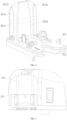
- the sterile adapter 200 includes a backboard 250 placed on a rear side of the body structure 210 of the sterile adapter 200 and perpendicular to the upper surface 211 of an upper shell of the sterile adapter 200.
- the backboard 250 has a side surface facing the surgical instrument 300, i.e., a front side surface of the backboard 250, which interfaces with a rear side of the surgical instrument box 310.
- the backboard 250 also has a rear side surface adhesive with a sterile cloth along an edge of the backboard 250 to isolate the sterile cloth from the surgical instrument 300, or the rear side surface exist in isolation while the sterile cloth is adhesive with the body structure 210 of the sterile adapter 200.
- the backboard 250 isolates the surgical instrument 300 from the sterile cloth to avoid frictional damage to the sterile cloth due to contact between the surgical instrument 300 and the sterile cloth.
- the backboard 250 plays a role of guide limitation during mounting.
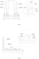
- a body of the backboard 250 is a plate-like structure, and guiding grooves 2511 running through from top to bottom of the backboard 250 are defined on the front side surface of the backboard 250.
- the surgical instrument box 310 includes protrusions 313 each capable of fitting with a respective guiding groove 2511, i.e., a width of each protrusion 313 is not greater than a width of each guiding groove 2511.
- Each protrusion 313 is provided in such a way as to be perfectly fitted with a structure of a respective guiding groove 2511 or only with a lower portion of the guiding groove 2511.
- the guiding grooves 2511 have the structures running through from top to bottom, so that the surgical instrument 300 is mounted from top to bottom.
- Each guiding groove 2511 includes a plane 2511a that is perpendicular to the upper surface of the sterile adapter 200, which is also an XZ plane.
- This XZ plane limits a respective protrusion 313 from moving in the Y direction, and when the surgical instrument 300 is mounted, the protrusion 313 directly abuts against a portion of the XZ plane without adjusting a mounting position in the Y direction.
- each guiding groove 2511 further includes a first wall 2511b and a second wall 2511c that are perpendicular to the XY plane.
- a distance between the first wall 2511b and the second wall 2511c along the Z direction from top to bottom has a changed part, i.e., the width of the guide groove 2511, along the Z direction from top to bottom, has a part varies from greater to lesser, i.e., the width of the guide groove 2511 is gradually changed from wider to narrower.
- This part of the structure is able to guide the protrusion 313 to move in the X direction, i.e., there is a certain space in the X direction to allow the protrusion 313 to adjust its position. Besides, no more effort is required when the protrusion 313 is inserted into the guiding groove 2511. Meanwhile, the distance between the first wall 2511b and the second wall 2511c has an unchanged part, i.e., the width of the guiding groove 2511 is constant in this part.
- the width of the guiding groove 2511 gradually decreases to be perfectly fitted to the protrusion 313, the width of the guiding groove 2511 no longer changes, i.e., the guiding groove 2511 limits the protrusion 313 from moving in the X direction, and the protrusion 313 continues to move downwardly in the Z direction.
- one guiding groove 2511 is defined, or two guiding grooves 2511 are defined.
- the two guiding grooves 2511 have a surface 2512 between them.
- an upper portion 2512a of the surface 2512 is provided as a beveled face for guiding the surgical instrument 300 to move in the Y direction.
- a lower portion 2512b of the surface 2512 is provided as a vertical face, i.e., a face parallel to the XZ plane, for limiting the surgical instrument 300 from moving in the Y direction.
- the guiding is also able to be accomplished by means of adjacent first walls 2511b and second walls 2511 c of the two guiding grooves 2511, with the connecting surface between the two guiding grooves 2511.
- the surgical instrument box 310 and the sterile adapter 200 may also be provided with precise guiding and precise positioning.
- the precise guiding and precise positioning are set up in conjunction with the connection structure of the non-transmission parts of the sterile adapter 200 and the surgical instrument box 310.
- the sterile adapter 200 and the surgical instrument box 310 are connected by means of a plurality of hooks 213 provided on the sterile adapter 200 and a plurality of movable hooks 3311 provided on the surgical instrument box 310, each of the plurality of movable hooks 3311 on the surgical instrument box 310 being snap-fit in a vertical direction to a respective hook 213 on the sterile adapter 200.
- the sterile adapter 200 includes the plurality of hooks 213 protruding from the upper surface 211.
- two sets of hooks 213 are integrally molded with the upper shell of the sterile adapter 200.
- Each hook 213 of the sterile adapter 200 has a snap surface 2131, and the snap surface 2131 is oriented downward so that an upper portion of the hook 213 does not need to be connected with a respective movable hook 3311 of the surgical instrument box 310.
- each hook 213 has a smooth curved-surface structure in the X direction and Y direction at an upper end.
- the upper end of each hook 213 is provided with a first guiding surface 2132 extending to left and right sides of the hook 213.
- the upper end of each hook 213 is provided with a second guiding surface 2133 extending to front and rear sides of the hook 213.
- each hook 213 is provided with a fitting surface 2134 that is flat in a YZ plane.
- a lower end of the front side of each hook 213, i.e., a portion of the hook 213 adjacent to a front side of the sterile adapter 200, has a curvilinear surface around a Z axis, which is a vertical positioning portion 2135 of the hook 213.
- a lower end of the rear side of the hook 213, i.e., a portion of the hook 213 adjacent to the backboard 250, has a slope surface, which is a third guiding portion 2136 of the hook 213.
- the first guiding surface 2132, the second guiding surface 2133, the flat fitting surface 2134, the vertical positioning portion 2135 and the third guiding portion 2136 of the hook 213 are all in continuous smooth transition.
- a plurality of recesses 3123 are defined on the lower surface 301 of the surgical instrument box 310 for the snap fit of the hooks, and each movable hook 3311 of the surgical instrument 300 is placed in a respective recess 3123.
- Each recess 3123 has smooth curved-surface structures in both the X direction and the Y direction, which is capable of being perfectly fitted to the hook 213.
- the smooth curved-surface structures in both the X direction and the Y direction are provided at an entrance 3123a of each recess 3123.
- the recess 3123 has a curved surface inside that is fitted to the upper end of the hook 213.
- the hooks 213 of the sterile adapter 200 and the recesses 3123 of the surgical instrument 300 in the embodiments are not only capable of connecting the sterile adapter 200 and the surgical instrument 300, but also capable of guiding. Meanwhile, due to the fitting of surfaces of the sterile adapter 200 and the surgical instrument 300, there is a certain degree of rigidity in the surfaces that are fitted, which reduces to a certain extent the cumulative tolerance due to the movable snap-fit manner of the movable hooks 3311 and the hooks 213.
- the surgical instrument box 310 includes a base 312 for mounting a steel wire pole, and a lower end of the steel wire pole is a drive connection for the surgical instrument 300.
- a movable hook assembly is provided on the base 312.
- the movable hook assembly includes the plurality of movable hooks 3311, and each movable hook 3311 has a snap surface 33111 facing upward, so that the movable hook 3311 is snap-fit to a respective hook 213 in the vertical direction.
- the movable hook assembly includes movable members (not identified in the figures), each movable member includes two movable hooks 3311 and a connecting arm 3312 between the two movable hooks 3311.
- the connecting arm 3312 has a length such that the two movable hooks 3311 are disposed spaced apart from each other.
- Connecting arms 3312 of the two movable hook assemblies are disposed on the left and right sides of the base, i.e., on the left and right sides inside the surgical instrument box 310.
- Each connecting arm 3312 extends in a direction along a front-rear direction, i.e., the Y direction, of the surgical instrument box 310.
- the connecting arm 3312 is fixedly connected to the two movable hooks 3311 so that the three become one.
- each movable hook 3311 Due to the limitation of the transmission portion within the surgical instrument box 310, a locked position and an unlocked position of each movable hook 3311 are limited to be located in a lengthwise direction of the connecting arm 3312, i.e., a movement direction of the movable hook 3311 is along the lengthwise direction of the connecting arm 3312.
- the movable hook assembly further includes guiding rods 332, and both ends of each guiding rod 332 are fixedly connected to the base 312 via two guiding rod seats 3121.
- Each connecting arm 3312 defines a guiding groove (not shown) for a respective guiding rod 332 to pass through, and the guiding rod 332 passes through the guiding groove in the connecting arm 3312 to enable the connecting arm 3312 to move along the guiding rod 332.
- a distance between both ends of the guiding rod 332 is the maximum distance for the connecting arm 3312 to move.
- a spring (not shown) is provided at one end of each guiding rod 332 such that one end of the spring abuts against the connecting arm 3312 and the other end of the spring abuts against the guiding rod seat 3121.
- the driving force of the spring causes the connecting arm 3312 and the movable hook 3311 to be in the locked position. Accordingly, an opening direction of the snap surface 2131 of each hook 213 on the upper surface of the sterile adapter 200 is toward the direction of movement of the movable hook 3311.
- the guiding rods 332 and the connecting arms 3312 are placed within the surgical instrument box 310, and as such, the recesses 3123 is provided on the base 312 to provide spaces for the movable hooks 3311 to move, as well as locations for being snap-fit to the hooks 213.
- the movable hook assembly further includes operating portions.
- each operating portion moves in a different direction than a direction of movement of a respective connecting arm 3312. That is, the operating portion is non-fixedly connected to the movable member.
- each movable member has a passive portion 3313, and the passive portion 3313 is fixedly disposed on a respective connecting arm 3312.
- the passive portion 3313 is integrally molded with other components of the movable member.
- Each operating portion includes an actuating portion 3322, and the actuating portion 3322 has an actuating surface such that a respective passive portion 3313 and the actuating surface are capable of forming line contact or surface contact, and the actuating surface of the actuating portion 3322 is capable of including a trajectory of the passive portion 3313.
- the actuating surface is a beveled or curved surface and the passive portion 3313 includes a beveled or curved surface.
- the actuating surface has a component along the lengthwise direction of the connecting arm 3312 of the movable member and a component along a left-right direction of the surgical instrument 300.
- the passive portion 3313 is provided as a bearing, and the passive portion 3313 rolls on the actuating surface of the actuating portion 3322.
- each operating portion further includes an operating button 3321, and the operating button 3321 is fixedly connected to a respective actuating portion 3322.
- the operating buttons 3321 are provided on both sides of the surgical instrument box 310 respectively, and the operating portions need to be pressed inwardly from both sides of the surgical instrument 300 during use, so that the operating portions move in a spanwise direction of the surgical instrument box 310, i.e., the X direction.
- This enables the force on each passive portion 3313 to break down the force along the front-rear direction of the surgical instrument box 310, i.e., the Y direction, so that each actuating portion 3322 drives a respective connecting arm 3312 as well as movable hooks 3311 to move in a direction of unlocking.
- the movable hook assembly further includes a guiding member 334 that assists in guiding the movement of the operating portion.
- each operating portion further includes a guiding portion 3323
- the guide member 334 includes guiding portions 3341.
- Each guiding portion 3341 of the guiding member 334 has a number of fitting surfaces with the guiding portion 3323 of a respective operating portion in the spanwise direction of the surgical instrument box 310, i.e., guiding directions of the guiding member 334 and the guiding portion 3341 are the X direction.
- a spring (not shown) is further provided between the operating portion and the guiding member 334 such that one end of the spring abuts against the operating portion and the other end of the spring abuts against the guiding member 334.
- each operating portion is further provided with a limit waist hole 3324, and a respective limit pole 3122 is fixedly provided on the base 312.
- the limit pole 3122 passes through the limit waist hole 3324 in order to, on the one hand, avoid the operating portion from being detached from the surgical instrument box 310, and on the other hand, make the two sides of the limit waist hole 3324 to be unlocked and locked positions of the operating portion.
- the docking of the surgical instrument 300 with the sterile adapter 200 is performed as follows.
- the surgical instrument 300 is moved to the top of the sterile adapter 200 and the at least one protrusion 313 on the surgical instrument 300 respectively abuts against the plane of the at least one guiding groove 2511 of the backboard 250 of the sterile adapter 200, and then the surgical instrument 300 is moved downwardly along the at least one guiding groove 2511 until the upper portion of each the at least one guiding groove 2511 completes coarse guiding of the surgical instrument 300.
- the at least one protrusion 313 on the surgical instrument box 310 causes the back end of the surgical instrument 300 to no longer swing from side to side, and the surgical instrument 300 is coarsely positioned by the lower portion of each of the at least one guiding groove 2511 of the backboard 250 of the sterile adapter 200, and then the surgical instrument 300 continues to move downwardly.
- the entrance 3123a of each recess 3123 of the surgical instrument box 310 contacts the upper end of each hook 213 of the sterile adapter 200, and then the surgical instrument 300 is guided by the fitting of surfaces of each recess 3123 and each hook 213 to complete precise guiding so as to make the surgical instrument box 310 and the sterile adapter 200 accurately aligned.
- the surgical instrument box 310 continues to move downward, accomplishing the snap fit between the movable member and the hooks 213, and then the surgical instrument box 310 and the sterile adapter 200 are mounted in place.
- the whole process is a continuous process, which does not require the user to spend much effort to adjust the position of the surgical instrument box 310, and is more convenient to use.
Landscapes
- Health & Medical Sciences (AREA)
- Surgery (AREA)
- Life Sciences & Earth Sciences (AREA)
- Engineering & Computer Science (AREA)
- Heart & Thoracic Surgery (AREA)
- Biomedical Technology (AREA)
- Nuclear Medicine, Radiotherapy & Molecular Imaging (AREA)
- Medical Informatics (AREA)
- Molecular Biology (AREA)
- Animal Behavior & Ethology (AREA)
- General Health & Medical Sciences (AREA)
- Public Health (AREA)
- Veterinary Medicine (AREA)
- Robotics (AREA)
- Pathology (AREA)
- Oral & Maxillofacial Surgery (AREA)
- Surgical Instruments (AREA)
Applications Claiming Priority (2)
| Application Number | Priority Date | Filing Date | Title |
|---|---|---|---|
| CN202110796258.7A CN113349936A (zh) | 2021-07-14 | 2021-07-14 | 一种无菌适配器与手术器械后端的导向定位结构 |
| PCT/CN2022/100532 WO2023284508A1 (fr) | 2021-07-14 | 2022-06-22 | Structure de guidage et de positionnement d'adaptateur stérile et d'instrument chirurgical |
Publications (2)
| Publication Number | Publication Date |
|---|---|
| EP4356862A1 true EP4356862A1 (fr) | 2024-04-24 |
| EP4356862A4 EP4356862A4 (fr) | 2024-10-02 |
Family
ID=77539492
Family Applications (1)
| Application Number | Title | Priority Date | Filing Date |
|---|---|---|---|
| EP22841148.4A Pending EP4356862A4 (fr) | 2021-07-14 | 2022-06-22 | Structure de guidage et de positionnement d'adaptateur stérile et d'instrument chirurgical |
Country Status (4)
| Country | Link |
|---|---|
| US (1) | US20240138950A1 (fr) |
| EP (1) | EP4356862A4 (fr) |
| CN (1) | CN113349936A (fr) |
| WO (1) | WO2023284508A1 (fr) |
Families Citing this family (8)
| Publication number | Priority date | Publication date | Assignee | Title |
|---|---|---|---|---|
| CN113349936A (zh) * | 2021-07-14 | 2021-09-07 | 深圳康诺思腾科技有限公司 | 一种无菌适配器与手术器械后端的导向定位结构 |
| WO2023284506A1 (fr) * | 2021-07-14 | 2023-01-19 | 深圳康诺思腾科技有限公司 | Structures de raccordement et robot chirurgical |
| CN113349937B (zh) * | 2021-07-14 | 2025-08-01 | 深圳康诺思腾科技有限公司 | 一种手术机器人的器械驱动传动机构及装配机构 |
| CN113842220A (zh) * | 2021-10-29 | 2021-12-28 | 常州唯精医疗机器人有限公司 | 微创手术机器人 |
| CN116172706A (zh) * | 2021-11-29 | 2023-05-30 | 深圳康诺思腾科技有限公司 | 用于手术机器人的无菌适配器、手术器械盒、器械驱动器和手术机器人 |
| WO2024145418A1 (fr) * | 2022-12-28 | 2024-07-04 | Vicarious Surgical Inc. | Ensemble plaque de champ |
| EP4510961B1 (fr) * | 2023-07-04 | 2025-08-20 | Lem Surgical Ag | Porte-outils chirurgicaux robotiques |
| CN118476874B (zh) * | 2024-05-27 | 2026-02-17 | 上海卓昕医疗科技有限公司 | 一种无菌适配器及医用手术机器人的执行末端 |
Family Cites Families (15)
| Publication number | Priority date | Publication date | Assignee | Title |
|---|---|---|---|---|
| AT90979B (de) * | 1920-05-07 | 1923-01-25 | Xylos Holztechnisches Unterneh | Verbindung für Holzbetten. |
| US9931167B2 (en) * | 2012-02-15 | 2018-04-03 | Intuitive Surgical Operations, Inc. | Minimally invasive surgical instrument to provide needle-based therapy |
| KR102731855B1 (ko) * | 2013-08-15 | 2024-11-20 | 인튜어티브 서지컬 오퍼레이션즈 인코포레이티드 | 예압형 수술 기구 인터페이스 |
| EP3119316B1 (fr) * | 2014-03-17 | 2020-05-27 | Intuitive Surgical Operations, Inc. | Drapeau sterile avec adaptateur sterile comprenant une référence de montage pour un instrument chirurgical |
| EP3310288A4 (fr) * | 2015-06-19 | 2019-03-06 | Covidien LP | Commande d'instruments chirurgicaux robotiques à couplage bidirectionnel |
| CN113274140B (zh) * | 2015-09-09 | 2022-09-02 | 奥瑞斯健康公司 | 手术覆盖件 |
| CN113349932A (zh) * | 2016-12-20 | 2021-09-07 | 威博外科公司 | 用于机器人外科系统的无菌适配器控制系统和通信接口 |
| US11160621B2 (en) * | 2017-11-17 | 2021-11-02 | Intuitive Surgical Operations, Inc. | Surgical instrument sterile adapter with optical coupler |
| JP2019122769A (ja) * | 2018-01-12 | 2019-07-25 | エスエス イノベーションズ チャイナ カンパニー リミテッドSS Innovations China Co. Ltd | ロボット手術システムのために滅菌アダプタアセンブリをアクチュエータアセンブリに固定させるロック装置 |
| JP6902003B2 (ja) * | 2018-08-28 | 2021-07-14 | 株式会社メディカロイド | 滅菌ドレープおよび手術器具の取付方法 |
| CN111374771B (zh) * | 2018-12-29 | 2024-07-26 | 达科为(深圳)医疗设备有限公司 | 一种无菌适配器 |
| CN111547250A (zh) * | 2020-05-22 | 2020-08-18 | 上海芝松航空科技有限公司 | 一种无人机电池仓 |
| CN113349936A (zh) * | 2021-07-14 | 2021-09-07 | 深圳康诺思腾科技有限公司 | 一种无菌适配器与手术器械后端的导向定位结构 |
| CN216702631U (zh) * | 2021-07-14 | 2022-06-10 | 深圳康诺思腾科技有限公司 | 一种无菌适配器与手术器械后端的导向定位结构 |
| CN113349937B (zh) * | 2021-07-14 | 2025-08-01 | 深圳康诺思腾科技有限公司 | 一种手术机器人的器械驱动传动机构及装配机构 |
-
2021
- 2021-07-14 CN CN202110796258.7A patent/CN113349936A/zh active Pending
-
2022
- 2022-06-22 EP EP22841148.4A patent/EP4356862A4/fr active Pending
- 2022-06-22 WO PCT/CN2022/100532 patent/WO2023284508A1/fr not_active Ceased
-
2024
- 2024-01-10 US US18/409,685 patent/US20240138950A1/en active Pending
Also Published As
| Publication number | Publication date |
|---|---|
| EP4356862A4 (fr) | 2024-10-02 |
| WO2023284508A1 (fr) | 2023-01-19 |
| US20240138950A1 (en) | 2024-05-02 |
| CN113349936A (zh) | 2021-09-07 |
Similar Documents
| Publication | Publication Date | Title |
|---|---|---|
| EP4356862A1 (fr) | Structure de guidage et de positionnement d'adaptateur stérile et d'instrument chirurgical | |
| US12496148B2 (en) | Surgery supporting apparatus for controlling motion of robot arm | |
| EP2335635B1 (fr) | Pince et systeme pour accessoires chirurgicaux | |
| EP3616642B1 (fr) | Adaptateur et procédé de fixation d'un instrument chirurgical sur un bras de robot à l'aide d'un adaptateur | |
| CN113288430B (zh) | 无菌板组件、手术器械、动力盒及手术机器人系统 | |
| EP4331523A1 (fr) | Dispositif d'entrée, dispositif d'actionnement principal et robot chirurgical | |
| US20150005784A2 (en) | Device for Supporting and Positioning of a Surgical Instrument and/or an Endoscope for Use in Minimal-Invasive Surgery and a Surgical Robotic System | |
| CN101421080A (zh) | 具有柱面坐标类型的操作器臂的医疗机器人系统 | |
| JP6562174B1 (ja) | 手術支援装置 | |
| CN113693727A (zh) | 一种手术机器人的装配机构 | |
| JP2020065904A (ja) | 手術支援装置 | |
| CN215306655U (zh) | 一种手术机器人 | |
| CN113349938B (zh) | 一种手术机器人 | |
| CN217660121U (zh) | 用于手术机器人的无菌适配器、手术器械盒、器械驱动器和手术机器人 | |
| US20230414306A1 (en) | Integrated robotic intraocular snake | |
| CN216702631U (zh) | 一种无菌适配器与手术器械后端的导向定位结构 | |
| US20240261042A1 (en) | Drape unit with cover, locking cover, and medical robot | |
| CN216823642U (zh) | 一种手术机器人的装配机构 | |
| US20220117691A1 (en) | Adaptor, method of detaching adaptor from robot arm, and robotic surgical system | |
| US12102405B2 (en) | Medical robot, surgical tool and attachment portion | |
| EP4460260B1 (fr) | Dispositifs de réglage pour positionner un manipulateur utérin | |
| CN221904068U (zh) | 用于联接手术器械和操纵器的无菌适配器 | |
| US12616532B2 (en) | Medical robot and attachment portion of medical robot | |
| US20220313376A1 (en) | Medical robot and attachment portion of medical robot | |
| KR20260007127A (ko) | 조향 가능한 의료기구 |
Legal Events
| Date | Code | Title | Description |
|---|---|---|---|
| STAA | Information on the status of an ep patent application or granted ep patent |
Free format text: STATUS: THE INTERNATIONAL PUBLICATION HAS BEEN MADE |
|
| PUAI | Public reference made under article 153(3) epc to a published international application that has entered the european phase |
Free format text: ORIGINAL CODE: 0009012 |
|
| STAA | Information on the status of an ep patent application or granted ep patent |
Free format text: STATUS: REQUEST FOR EXAMINATION WAS MADE |
|
| 17P | Request for examination filed |
Effective date: 20240115 |
|
| AK | Designated contracting states |
Kind code of ref document: A1 Designated state(s): AL AT BE BG CH CY CZ DE DK EE ES FI FR GB GR HR HU IE IS IT LI LT LU LV MC MK MT NL NO PL PT RO RS SE SI SK SM TR |
|
| A4 | Supplementary search report drawn up and despatched |
Effective date: 20240829 |
|
| RIC1 | Information provided on ipc code assigned before grant |
Ipc: A61B 18/00 20060101ALN20240823BHEP Ipc: A61B 17/00 20060101ALN20240823BHEP Ipc: A61B 34/00 20160101ALI20240823BHEP Ipc: A61B 90/00 20160101ALI20240823BHEP Ipc: A61B 34/30 20160101AFI20240823BHEP |
|
| DAV | Request for validation of the european patent (deleted) | ||
| DAX | Request for extension of the european patent (deleted) | ||
| STAA | Information on the status of an ep patent application or granted ep patent |
Free format text: STATUS: EXAMINATION IS IN PROGRESS |
|
| 17Q | First examination report despatched |
Effective date: 20251021 |