EP4357044A1 - Avancement modulaire - Google Patents
Avancement modulaire Download PDFInfo
- Publication number
- EP4357044A1 EP4357044A1 EP22203035.5A EP22203035A EP4357044A1 EP 4357044 A1 EP4357044 A1 EP 4357044A1 EP 22203035 A EP22203035 A EP 22203035A EP 4357044 A1 EP4357044 A1 EP 4357044A1
- Authority
- EP
- European Patent Office
- Prior art keywords
- feed
- side support
- conveying direction
- module
- modules
- Prior art date
- Legal status (The legal status is an assumption and is not a legal conclusion. Google has not performed a legal analysis and makes no representation as to the accuracy of the status listed.)
- Withdrawn
Links
Images






Classifications
-
- B—PERFORMING OPERATIONS; TRANSPORTING
- B65—CONVEYING; PACKING; STORING; HANDLING THIN OR FILAMENTARY MATERIAL
- B65H—HANDLING THIN OR FILAMENTARY MATERIAL, e.g. SHEETS, WEBS, CABLES
- B65H1/00—Supports or magazines for piles from which articles are to be separated
- B65H1/26—Supports or magazines for piles from which articles are to be separated with auxiliary supports to facilitate introduction or renewal of the pile
- B65H1/266—Support fully or partially removable from the handling machine, e.g. cassette, drawer
-
- B—PERFORMING OPERATIONS; TRANSPORTING
- B21—MECHANICAL METAL-WORKING WITHOUT ESSENTIALLY REMOVING MATERIAL; PUNCHING METAL
- B21D—WORKING OR PROCESSING OF SHEET METAL OR METAL TUBES, RODS OR PROFILES WITHOUT ESSENTIALLY REMOVING MATERIAL; PUNCHING METAL
- B21D43/00—Feeding, positioning or storing devices combined with, or arranged in, or specially adapted for use in connection with, apparatus for working or processing sheet metal, metal tubes or metal profiles; Associations therewith of cutting devices
- B21D43/02—Advancing work in relation to the stroke of the die or tool
- B21D43/04—Advancing work in relation to the stroke of the die or tool by means in mechanical engagement with the work
- B21D43/10—Advancing work in relation to the stroke of the die or tool by means in mechanical engagement with the work by grippers
- B21D43/11—Advancing work in relation to the stroke of the die or tool by means in mechanical engagement with the work by grippers for feeding sheet or strip material
-
- F—MECHANICAL ENGINEERING; LIGHTING; HEATING; WEAPONS; BLASTING
- F16—ENGINEERING ELEMENTS AND UNITS; GENERAL MEASURES FOR PRODUCING AND MAINTAINING EFFECTIVE FUNCTIONING OF MACHINES OR INSTALLATIONS; THERMAL INSULATION IN GENERAL
- F16C—SHAFTS; FLEXIBLE SHAFTS; ELEMENTS OR CRANKSHAFT MECHANISMS; ROTARY BODIES OTHER THAN GEARING ELEMENTS; BEARINGS
- F16C29/00—Bearings for parts moving only linearly
- F16C29/005—Guide rails or tracks for a linear bearing, i.e. adapted for movement of a carriage or bearing body there along
-
- F—MECHANICAL ENGINEERING; LIGHTING; HEATING; WEAPONS; BLASTING
- F16—ENGINEERING ELEMENTS AND UNITS; GENERAL MEASURES FOR PRODUCING AND MAINTAINING EFFECTIVE FUNCTIONING OF MACHINES OR INSTALLATIONS; THERMAL INSULATION IN GENERAL
- F16C—SHAFTS; FLEXIBLE SHAFTS; ELEMENTS OR CRANKSHAFT MECHANISMS; ROTARY BODIES OTHER THAN GEARING ELEMENTS; BEARINGS
- F16C29/00—Bearings for parts moving only linearly
- F16C29/008—Systems with a plurality of bearings, e.g. four carriages supporting a slide on two parallel rails
-
- F—MECHANICAL ENGINEERING; LIGHTING; HEATING; WEAPONS; BLASTING
- F16—ENGINEERING ELEMENTS AND UNITS; GENERAL MEASURES FOR PRODUCING AND MAINTAINING EFFECTIVE FUNCTIONING OF MACHINES OR INSTALLATIONS; THERMAL INSULATION IN GENERAL
- F16C—SHAFTS; FLEXIBLE SHAFTS; ELEMENTS OR CRANKSHAFT MECHANISMS; ROTARY BODIES OTHER THAN GEARING ELEMENTS; BEARINGS
- F16C29/00—Bearings for parts moving only linearly
- F16C29/04—Ball or roller bearings
- F16C29/06—Ball or roller bearings in which the rolling bodies circulate partly without carrying load
- F16C29/063—Ball or roller bearings in which the rolling bodies circulate partly without carrying load with a bearing body, e.g. a carriage or part thereof, provided between the legs of a U-shaped guide rail or track
-
- B—PERFORMING OPERATIONS; TRANSPORTING
- B65—CONVEYING; PACKING; STORING; HANDLING THIN OR FILAMENTARY MATERIAL
- B65H—HANDLING THIN OR FILAMENTARY MATERIAL, e.g. SHEETS, WEBS, CABLES
- B65H2301/00—Handling processes for sheets or webs
- B65H2301/30—Orientation, displacement, position of the handled material
- B65H2301/31—Features of transport path
- B65H2301/311—Features of transport path for transport path in plane of handled material, e.g. geometry
- B65H2301/31124—U-shaped
-
- B—PERFORMING OPERATIONS; TRANSPORTING
- B65—CONVEYING; PACKING; STORING; HANDLING THIN OR FILAMENTARY MATERIAL
- B65H—HANDLING THIN OR FILAMENTARY MATERIAL, e.g. SHEETS, WEBS, CABLES
- B65H2405/00—Parts for holding the handled material
- B65H2405/50—Gripping means
- B65H2405/55—Rail guided gripping means running in closed loop, e.g. without permanent interconnecting means
- B65H2405/552—Rail guided gripping means running in closed loop, e.g. without permanent interconnecting means with permanent interconnection and determined spacing between the grippers
- B65H2405/5521—Rail guided gripping means running in closed loop, e.g. without permanent interconnecting means with permanent interconnection and determined spacing between the grippers details of interconnection, e.g. chain, link
-
- F—MECHANICAL ENGINEERING; LIGHTING; HEATING; WEAPONS; BLASTING
- F16—ENGINEERING ELEMENTS AND UNITS; GENERAL MEASURES FOR PRODUCING AND MAINTAINING EFFECTIVE FUNCTIONING OF MACHINES OR INSTALLATIONS; THERMAL INSULATION IN GENERAL
- F16C—SHAFTS; FLEXIBLE SHAFTS; ELEMENTS OR CRANKSHAFT MECHANISMS; ROTARY BODIES OTHER THAN GEARING ELEMENTS; BEARINGS
- F16C2326/00—Articles relating to transporting
- F16C2326/58—Conveyor systems, e.g. rollers or bearings therefor
Definitions
- the present invention relates to a feed, in particular a modular feed, for conveying a workpiece such as strip material.
- the feed comprises side support modules and a base support module, which are designed such that feeds can be formed for different feed applications.
- Material conveying devices in particular feeds such as gripper feeds or roller feeds, are used for conveying and feeding, in particular for the timed feeding of workpieces such as strip material or band material.
- gripper feeds or roller feeds are used in progressive cutting tools such as punching applications.
- the workpiece is fed forward in a timed manner, with the timing of the feed being synchronized with a punching tool.
- the principle of the feed is illustrated using a strip material in the pliers feed as an example:
- the pliers feed can comprise a fixed pliers and a movable pliers.
- the stationary strip material is held or clamped by the fixed pliers.
- the movable pliers are in a starting position.
- a control signal usually initiated by a subsequent cutting tool, causes the movable pliers to clamp the strip material and at the same time the fixed pliers release the clamp ("release").
- the movable pliers then carry out a linear feed movement to an end position.
- the feed movement can be specified by a control system.
- the fixed pliers clamp the strip material again and the movable pliers release the clamp.
- the movable pliers then carry out a linear movement back to the starting position.
- the previously described process can also be described as a cycle or feed cycle. The feed cycle is repeated as often as a controller receives a start signal.
- a gripper feed also includes a base body (or support structure) that provides stability to the feed and can accommodate moving components and/or drive units. Typically, the moving gripper moves along a longitudinal direction of the base body.
- a feed for example a gripper feed
- the production and procurement of the feed should be simplified and cost-effective.
- the production of the feed components should be cost-effective.
- feeds should be able to be flexibly converted and/or adapted to cover different areas of application. For example, different areas of application/requirements such as feed lengths, feed widths, contact forces (for holding the image material), feed cycles per unit of time (cycle rate, thus acceleration of the moving components) should be able to be served.
- Component dimensions of the feeds should also be reduced due to space restrictions in factory halls.
- Conventional feeds do not meet this requirement profile.
- Conventional feeds for example, have integral and bulky components, whereby the components are only designed for one purpose, one assembly orientation and one assembly position.
- conventional feeds are limited to a specific area of application. For a different area of application, a completely different and new feed must be purchased. These feeds are therefore very inefficient overall. If a component is damaged, purchasing a replacement component is usually costly and time-consuming.
- An object of the present invention is therefore to overcome the disadvantages of the prior art.
- the present invention is dedicated to the task of providing a feed for conveying a workpiece, which is modular and can be flexibly modified for different areas of application. The modification should be able to be carried out cost-effectively. It is also an object of the invention to provide modules/components for a feed, so that a simple modification is efficiently possible.
- a structurally compact feed system should be provided.
- the conveyance of strip material should be safe, less susceptible to failure and quick.
- a first embodiment of the invention relates to a feed for conveying a workpiece, in particular strip material, in a conveying direction, comprising: at least a first pair of side support modules; a base support module arranged between the side support modules; and at least one conveyor module; wherein the side support modules are detachably connected to the base support module transversely to the conveying direction in order to form a U-shaped support structure of the feed along the conveying direction; wherein the conveyor module is arranged on the support structure so as to be movable in the conveying direction.
- the feed according to the invention (also referred to without restriction and merely for clarity as a "modular" feed) comprises components that make it possible to provide feeds for different requirements in a flexible manner.
- the feed can be easily upgraded, converted and/or changed in design.
- the components used are modular and can include mounting means/end faces that are universal, standardized and/or congruent with each other. This enables flexible assembly of the components to form a feed. This saves costs and contributes to a cheaper assembly of a feed.
- the requirements of the feeds may include a maximum installation space.
- the feed according to the invention enables a flexible conversion of an existing feed using similar components.
- a feed can then be formed that occupies a different installation space (for example a changed/smaller geometric dimension such as width/height/length).
- the feed components can be manufactured in large numbers and, in particular, in larger quantities.
- the production of these components can be optimized for the increased quantity, which makes production more efficient.
- the modules described here can be understood as “components" of the feed. However, a side support module and a base support module are to be understood here as a (single) integral component.
- the side support modules described here can in particular be of the same type or uniform.
- a "pair of side support modules” can be understood in such a way that the two side support modules in combination with the base support module as a support structure do not touch each other.
- a conveyor module may comprise several components as described herein.
- the strip material conveyed by the feeder could, for example, be used to manufacture components or precision parts for numerous industrial sectors, including the automotive, electrical and electronics, household goods, cosmetics, aerosol cans, medical technology or electrical steel sectors.
- the feeder may be adapted to feed strip material in two different directions, preferably in two opposite directions.
- a simple change of arrangement of components may be made to change one direction.
- a support plate of the feeder (through which strip material can be fed) may be mounted on one side and on the other along the feed direction.
- an end plate of the feeder may be mounted at any end of the support structure of the feeder.
- the holding devices can come into engagement with belt material. Consequently, the contact pressure on a belt material can be increased if necessary. In this way, it is possible to accelerate the strip material to a greater extent. This contributes to an increase in the throughput of strip material and makes the application of the feed efficient.
- the number of holding devices can be flexibly adjusted based on different thicknesses of the strip material, for example, in order to ensure a desired cycle rate. This ensures an overall more efficient processing of strip material in the feed, especially in feeds with progressive cutting tools.
- Conventional feeders lack such advantages because conventional feeders are limited to one application and are designed for that purpose only.
- Conventional components of conventional feeders are not modular and do not have standardized assembly means and/or symmetries that allow flexible assembly and conversion.
- the support structure of the feed according to the invention can be made up of three modules. This can be understood as meaning that the support structure is divided (divided into components).
- the support structure of the feed is to be understood as meaning that it offers sufficient stability to be able to operate the feed. For example, movements and loads can thus be absorbed by the conveyor module.
- the support structure can accommodate other components of the feed (e.g. a drive unit, magnetic rails, a carriage plate, movable holding devices) and offer stability to these other components. This would not be possible without such a support structure.
- Conventional support structures are integral, i.e. one-piece. For stability reasons, division of the support structures into individual components has not yet been provided for in conventional feed systems. In addition, it is not possible to string together conventional support structures.
- the support structure according to the invention (which is split but can be detachably connected) can be used in any way for feeds of different applications and/or requirements.
- the same first pair of side support modules can be used for feeds of a different width, e.g. for the application of a different strip material width.
- the U-shaped support structure can be understood in such a way that a profile in the cross section of the support structure at right angles to the conveying direction (longitudinal direction of the support structure) essentially simulates a U.
- the "U” can be designed in an angular manner and can include minor deviations from a normal "U".
- a second embodiment relates to the previous embodiment, wherein the side support modules can be detachably connected to the base support module in an interchangeable manner.
- This design increases modularity and enables flexible use of the components. For example, individual components can be replaced as required if they become damaged (for example during operation of the feed). This does not require any extensive changes to other components. Consequently, the undamaged part of the feed remains unchanged, which can reduce costs.
- the side support modules can also be procured/produced in advance, which results in cost savings due to the increased number of units. In contrast to replacing an entire support structure, it is possible to carry out a targeted and efficient replacement.
- a component of a feed can be replaced by another component of the same feed. This could be useful, for example, if the feed is subjected to a greater load on one side. Consequently, the components can be converted/exchanged so that a more even material load can be ensured overall. This increases the service life of the feed compared to conventional feeds.
- a third embodiment relates to one of the preceding embodiments, wherein the feed is designed such that the conveyor module can continue to be arranged on the support structure so as to be movable in the conveying direction when the side support modules are mutually exchanged.
- a fourth embodiment relates to one of the preceding embodiments, wherein the side support modules have first mounting means for detachable connection to the base support module.
- the detachable connection offers the advantage of simplified removal/conversion and/or simplified extension of the feed. This enables flexible assembly of the components to form a feed.
- a 5th embodiment relates to one of the preceding embodiments, wherein the side support modules have end faces which are designed such that a further pair of similar side support modules can be arranged in the conveying direction on the first pair of side support modules such that the length of the support structure is extended by the length of a side support module when the basic support module is replaced by an extended basic support module whose length is greater than the length of the basic support module by the length of a side support module.
- the other pair is also of the same type. This contributes to the efficient use of a plurality of identical components.
- the pairs of side support modules can be arranged in such a way that essentially two rows are formed, with the basic support module arranged between the rows.
- the basic support module only needs to be made longer, so that in one example a support structure that is twice as long can be achieved (for example, with three pairs a support structure that is three times as long as with one pair).
- the base support module it is also possible for the base support module to be wider.
- the same side support modules can still be used.
- a 6th embodiment relates to one of the preceding embodiments, wherein the feed is arranged in such a way that when a further pair of similar side support modules is arranged in The conveyor module can still be arranged on the support structure so that it can move in the conveying direction.
- a 7th embodiment relates to one of the preceding embodiments, wherein the side support modules and the base support module are designed such that when a further pair of similar side support modules is arranged in the conveying direction, the further similar side support modules can be detachably connected to the extended base support module transversely to the conveying direction in order to be able to form the support structure of the feed along the conveying direction.
- connection transverse to the conveying direction offers sufficient stability so that the support structure formed can withstand the loads of the feed during operation. As a result, the feed can be accommodated essentially safely.
- An 8th embodiment relates to one of the preceding embodiments, wherein the end faces of the side support modules are congruent with each other, so that when a further pair of similar side support modules is arranged, the end faces are at least partially flush with each other.
- Congruent to each other can mean that the surfaces are quite similar and have a matching shape to each other.
- a continuous transition from one side support module to another side support module along a series of side support modules can be enabled.
- a 9th embodiment relates to one of the preceding embodiments, wherein the end faces of the side support modules have recesses, preferably U-shaped recesses, wherein in an arrangement of a further pair of similar side support modules, the recesses form a common opening with a substantially continuous peripheral surface.
- the interior of the support structure is accessible via the outside for cables and/or hoses (e.g. pneumatic hoses) or similar. Consequently, the cables and/or hoses can already be connected at both ends and then inserted laterally through the recess. This means that the cables and/or hoses can already be pre-assembled.
- cables and/or hoses e.g. pneumatic hoses
- the "recesses” mean that one end face has a recess and the other end face also has a recess.
- the end faces can be understood as the two faces of a side support module arranged at opposite ends in the longitudinal direction of a side support module.
- the end faces are therefore oriented normal to the conveying direction and parallel to each other.
- the recess on one end face may be longer in the longitudinal direction than the recess on the other end face in the longitudinal direction. This can be advantageous because it allows more threaded holes to be provided on an outer side of the side support module towards the side with the shorter recess in the longitudinal direction to accommodate a sensor. Furthermore, sufficient access for cables and/or hoses is provided flexibly.
- the legs of the U-shaped recesses are arranged parallel to the conveying direction.
- a substantially continuous peripheral surface may mean that there are no strong and/or noticeable edges. However, manufacturing tolerances are included and should be taken into account, so edges may occur in some cases.
- a 10th embodiment relates to the preceding embodiment, wherein the end faces of the side support modules have second mounting means which are designed such that the side support modules can be detachably connected to an end plate of the feed.
- the first and second mounting means described herein can comprise fastening holes. It is then advantageously possible to line up the end faces of the side support modules lengthwise, whereby it is also possible to fasten the side support modules to the end plate.
- the end faces thus fulfil two functions, which increases flexibility. Conventional end faces are only designed for one function.
- At least the end faces on one side of the first pair of side support modules are detachably connected to the end plate. These end faces are to be understood as the two end faces of the two side support modules of the first pair of side support modules. These two end faces can lie on a common plane.
- An end plate (a second, similar one) can also be attached to the other side of the first pair of side support modules. However, a second pair of side support modules can also be arranged on the other side of the first pair of side support modules.
- An 11th embodiment relates to one of the preceding embodiments, wherein the base support module has first mounting means on both sides arranged transversely to the conveying direction, which are optionally designed for a force-fitting connection to the first mounting means of the side support modules.
- the first mounting means of the base support module are arranged in such a way that an exchange of the side support modules with one another still allows a detachable connection. This means that, for example during assembly, any side support module can be used and there is no need to select a separate one for one side.
- the first assembly means of the basic support module enable the additional pairs of side support modules to be detachably connected to the basic support module, even when additional pairs of side support modules are arranged in series.
- the stability of the supporting structure is thus ensured, while at the same time allowing the supporting structure to be divided into several components. It is not necessary to connect the pairs of side support modules to be detachably connected to one another, since the basic support module provides an (indirect) connection. In one example, this connection is made over the entire length of the pairs of side support modules lined up next to one another.
- the first mounting means can, for example, comprise fastening holes.
- screws can be passed through the first mounting means of the side support modules, which engage in the first mounting means of the base support module.
- a 12th embodiment relates to one of the preceding embodiments, wherein the side support modules are elongated and essentially define a U-shaped profile with legs of different lengths, wherein the smaller leg of each side support module is essentially flush with the base support module.
- the flush finish offers the advantage that, for example, a component arranged in the support structure can protrude over the basic support module and the flush finish. This means that a wider component (width is to be understood as being across the longitudinal direction) can be arranged in the support structure without cables, hoses or similar being damaged.
- the U-shaped profile can be understood as a profile in the cross section of the side support module at right angles to the conveying direction (longitudinal direction of the side support module) essentially simulating a U.
- the "U” can be designed in an angular manner and can include minor deviations from a normal "U".
- a 13th embodiment relates to one of the preceding embodiments, wherein the feed comprises a guide rail arranged on the support structure, and wherein the side support modules have third mounting means for detachably connecting the guide rail to a side support module, wherein, optionally, the guide rail and the third mounting means of the side support modules are arranged such that the Guide rail can be connected simultaneously to several side support modules arranged in the conveying direction.
- the guide rail can be designed in such a way that it accommodates movable components of the feed, for example the conveyor module. Furthermore, the guide rail can guide the conveyor module, for example, along the conveying direction in both directions (e.g. the conveyor module can be moved in both directions, with one of the directions corresponding to the conveying direction). The conveyor module can therefore carry out a translational movement.
- the feed can also comprise two guide rails, which are then arranged on both side support modules of the first pair of side support modules.
- the design also offers the advantage that several side support modules can be connected longitudinally with a guide rail. Consequently, the guide rails can fulfil two functions, namely guiding the conveyor module and increasing the stability of the feed.
- a 14th embodiment relates to one of the preceding embodiments, wherein the base support module has second mounting means which are, optionally, arranged in pairs along the conveying direction, wherein the feed comprises at least one drive unit, preferably an electric drive unit, most preferably a linear motor; wherein the drive unit is accommodated in the support structure and is designed to move the conveying module, wherein the second mounting means of the base support module are arranged such that the drive unit can be preferably detachably connected to the base support module at variable positions along the conveying direction.
- the drive unit can be positioned arbitrarily and flexibly in the longitudinal direction (parallel/along the conveying direction). Consequently, a desired overlap between the drive unit and the magnetic plate of the conveying module can be achieved.
- the position of the drive unit can be subsequently changed to another desired feed application, particularly in the case of an existing feed.
- the drive unit can, for example, be positioned at a first end of the support structure if it is desired that there is a large acceleration at the beginning of the conveyor module's travel path.
- the base support module can therefore have a plurality of spaced-apart fastening holes to enable adjustment of the drive unit in a longitudinal direction.
- the second mounting means can be arranged, for example, at equidistant intervals, or at equidistant intervals in sections in the longitudinal direction of the base support module (conveying direction).
- the second mounting means of the base support module are, for example, oriented at right angles to the first mounting means of the base support module.
- the drive unit can be limited by the support structure transversely to the conveying direction.
- the legs of the U-shaped support structure can limit the drive unit transversely to the conveying direction.
- a 15th embodiment relates to one of the preceding embodiments, further comprising two end plates which are detachably connected to the support structure, preferably not to the base support module, on opposite sides of the support structure.
- the opposite sides of the support structure can be considered to be opposite along the conveying direction.
- the end plates essentially define the ends of the support structure in the longitudinal direction (conveying direction).
- the end plates are detachably connected to the end faces of the side support modules (via the second mounting means of the side support modules). Fastening to the base support module is therefore advantageously not required.
- end plates it is possible for the end plates to extend beyond the faces of a pair of side support modules when connected to the support structure. This provides more space for assembly and can contribute to stability.
- a 16th embodiment relates to one of the preceding embodiments, wherein the end plates are designed such that the end plates can be releasably connected to the support structure in an interchangeable manner, wherein, optionally, the feed is designed such that the conveyor module can still be arranged on the support structure so as to be movable in the conveying direction when the end plates are mutually exchanged.
- the end plates may have mounting holes which are preferably arranged symmetrically on the end plates. Consequently, an exchange of the end plates to each other. This increases flexibility and contributes to modularity.
- a 17th embodiment relates to one of the preceding embodiments, wherein the end plates have a recess in the conveying direction, which is adapted to at least partially receive the conveying module during operation of the feed.
- the recess offers the advantage that the conveyor module can cover a longer travel path with the same overall length of the feed (measured by the distance between the outer sides of the end plates in the longitudinal direction). This means that a relatively longer travel path for the carriage plate/holding device(s) arranged on the conveyor module can be made possible and the strip material can thus be safely guided over a relatively longer path.
- An 18th embodiment relates to one of the preceding embodiments, wherein the length of the base support module in the conveying direction corresponds to the length of the first pair or pairs of side support modules.
- the base support modules described here are usually elongated, whereby the longitudinal direction can run along the conveying direction, in particular parallel to the conveying direction.
- the base support module can be integral and designed as one piece.
- a pair of side support modules is usually arranged so that the side support modules are opposite each other and therefore transverse to the conveying direction.
- the length of a pair of side support modules therefore corresponds to the length of one side support module. If several pairs of side support modules are lined up, the basic support module has the sum of the lengths of all pairs of side support modules. This increases the stability and robustness of the U-shaped support structure.
- the support structure can therefore be understood in such a way that the rows of side support modules are detachably connected on both sides to the individual basic support module in between.
- a 19th embodiment relates to one of the preceding embodiments, wherein the feed comprises at least one guide rail, wherein the length of the guide rail in the conveying direction corresponds to the length of the first pair or pairs of side support modules.
- the guide rail can extend over the entire length of the side support modules arranged in a row and thus form a detachable connection with them. This embodiment combines the advantages of the guide rail already described above.
- a 20th embodiment relates to one of the preceding embodiments, wherein the side support modules each have a length of a maximum of 250 mm, preferably a maximum of 210 mm, more preferably a maximum of 180 mm, more preferably a maximum of 150 mm, more preferably a maximum of 140 mm, more preferably a maximum of 135 mm, most preferably a maximum of 131 mm or 130 mm; and/or a length of at least 50 mm, preferably at least 70 mm, more preferably at least 90 mm, more preferably at least 110 mm, more preferably at least 120 mm, more preferably at least 125 mm, most preferably at least 129 mm.
- this length of the side support module creates a good compromise between, on the one hand, sufficient stability (longer length desirable) and, on the other hand, increased modularity of the feed (shorter length desirable).
- the side support modules can thus be manufactured in larger quantities and used in large numbers in a feed. This means that feeds for different feed applications can also be formed from the same components.
- the feed may comprise exactly one pair of side support modules, such that the feed has a feed length in the range of 120-140 mm, preferably 125-135 mm.
- the feed may comprise exactly two pairs of side support modules, so that the feed has a feed length in the range of 250-270 mm, preferably 255-265 mm.
- the feed may comprise exactly three pairs of side support modules, so that the feed has a feed length in the range of 380-400 mm, preferably 385-395 mm.
- the distance between two end plates can be a maximum of 500 mm, preferably a maximum of 450 mm, more preferably a maximum of 420 mm, further preferably a maximum of 400 mm, most preferably a maximum of 391 mm; and/or at least 70 mm, preferably at least 90 mm, more preferably at least 110 mm, most preferably at least 129 mm.
- a 21st embodiment relates to one of the preceding embodiments, wherein the first and optionally second and optionally third mounting means of the side support modules and optionally the first and optionally the second mounting means of the base support module are each arranged symmetrically on the respective modules.
- the symmetrical arrangement could be understood to mean that, for example, the mounting means have an equal distance from a main axis of the respective module. Furthermore, the mounting means can be shaped essentially the same.
- a 22nd embodiment relates to one of the preceding embodiments, further comprising one or more further pairs of similar side support modules, wherein the pairs of side support modules are arranged next to one another in the conveying direction, wherein the side support modules are detachably connected to the base support module transversely to the conveying direction in order to form the support structure of the feed along the conveying direction.
- a 23rd embodiment of the invention relates to a feed for conveying a workpiece, in particular strip material, in a conveying direction, comprising: a support structure which is formed along the conveying direction; and at least one conveying module which is arranged in the conveying direction is movably arranged on the support structure and comprises a carriage plate and at least one elongate holding device, which are preferably detachably connected to one another; wherein the longitudinal axis of the holding device runs substantially parallel to the normal of the carriage plate.
- the "elongated" holding device is to be understood in such a way that there is at least one dimension of the holding device that is longer than two dimensions oriented substantially perpendicular thereto (the dimensions can be understood as corresponding to the three spatial directions of a three-dimensional coordinate system).
- a narrow plate can also be understood as elongated if one side is longer than the two remaining sides (each perpendicular to the long side).
- the carriage plate can have a plate-like shape, which can also be flat. A normal can therefore be identified on this plate/surface.
- the carriage plate can have a surface that is larger than the other surfaces. The normal of the carriage plate is then usually understood as the normal of this larger surface.
- This embodiment of the invention offers the advantage that, for example, an existing feed can be rotated and can continue to be used as a feed.
- the feed can be rotated around the conveying direction, preferably by 85° to 95°, most preferably by 89° to 91°.
- the rotation described here can also take place in the opposite direction.
- the rotation can also include a rotation around the angles described here plus one or more times of 360°.
- This embodiment is advantageous for requirements such as those imposed by narrow strip materials and/or wires or similar. Wide holding devices are not necessary for these requirements. Consequently, the space required for the feed can be saved.
- a feed can be rotated and the rotated feed can be formed by assembling the same components, which has a smaller width.
- the structural design of the components can support rotation of the feed around the longitudinal axis of the feed. In some cases, structural adjustments can be made to the rotated feed in order to be able to operate it for a new requirement (as opposed to the non-rotated state).
- a 24th embodiment relates to the preceding embodiment, further comprising at least one end plate which is preferably detachably connected to the support structure on a side of the support structure lying along the conveying direction, wherein the end plate has a first dimension along the normal of the carriage plate which is less than a second dimension which is substantially perpendicular to the normal of the carriage plate and to the conveying direction.
- the first dimension described herein can also be understood as a width of the end plate for this embodiment.
- the feed is advantageously designed to be narrow and yet still operable.
- the second dimension is thus essentially perpendicular to the normal of the carriage plate and perpendicular to the conveying direction. In one example, this dimension can also be understood as the height for this embodiment.
- a 25th embodiment relates to the preceding embodiment, wherein the ratio of the second and first dimensions is at least 1.2, preferably at least 1.4, more preferably at least 1.6, more preferably at least 1.8, more preferably at least 2.0, more preferably at least 2.2, more preferably at least 2.4, more preferably at least 2.6, more preferably at least 2.8, more preferably at least 3.0, most preferably at least 3.2.
- a 26th embodiment relates to one of the embodiments 24 or 25, comprising a further similar end plate, wherein the end plates are connected to The sides of the support structure opposite to the conveying direction are preferably detachably connected to the support structure.
- An advantage of this embodiment is that the feed can be attached to a wall with a surface of the support structure and/or the end plates and can still be operated.
- the surface of the support structure and/or the end plates is to be understood as one that would normally run essentially parallel to a floor if the feed were to be operated lying down.
- a 27th embodiment relates to one of the embodiments 23 to 26, wherein the conveyor module comprises a flat magnetic rail which is connected to the carriage plate such that its normals run substantially parallel.
- the magnetic rail usually includes a magnet.
- the magnetic rail usually has a surface that is larger than the other surfaces.
- the normal of the magnetic rail is then usually understood as the normal of this larger surface.
- This embodiment has the advantage that the drive (via the magnetic rail, which is driven by the drive unit) runs essentially transversely to the holding devices. This means that a large overlap between a drive unit and the magnetic rail can be achieved (thus advantageous acceleration and cycle rates of the feed), while at the same time the space requirement is adapted and optimized to the requirements.
- a 28th embodiment relates to one of the embodiments 23 to 27, wherein the support structure has a U-shaped profile along the conveying direction, wherein the carriage plate of the conveyor module is arranged substantially on the legs of the U-shaped profile, and wherein the normal of the carriage plate is directed substantially from the web of the U-shaped profile to the opening of the U-shaped profile.
- the advantages mentioned above also apply to this embodiment.
- the U-shaped profile can be used to accommodate the drive unit. Consequently, the orientation of the U-shaped profile enables an optimized drive and space requirement.
- a 29th embodiment relates to one of the embodiments 24 to 28, wherein the end plates have at least two outer surfaces oriented substantially at right angles to each other.
- a 30th embodiment relates to one of the embodiments 23 to 29, wherein the carriage plate is designed such that the holding device can also be detachably connected to the carriage plate with its longitudinal axis at right angles to the normal of the carriage plate, and preferably also at right angles to the conveying direction.
- the holding devices can therefore be reoriented (e.g. rotated by 90°) and can still be detachably connected to the carriage plate in the rotated orientation.
- holding devices can be arranged on a narrow side of the feed.
- the same carriage plate and the same holding device can advantageously be used for this. This means that the components can be manufactured more cost-effectively.
- the holding device can be detachably connected in a first orientation to an upper side of the carriage plate and in a second orientation to an outer side of the carriage plate.
- the upper side of the carriage plate can, for example, be the opposite side of the side that faces the web of the U-shaped profile of the support structure.
- the opposite side of the side that faces a drive motor (which is accommodated within the U-shaped profile).
- the outer side of the carriage plate can laterally delimit the upper side of the carriage plate.
- the outer side can face a leg of the U-shaped profile of the support structure.
- a 31st embodiment relates to one of the embodiments 23 to 30, as long as dependent on the embodiment 24, wherein the dimension of the holding device in the longitudinal direction is a maximum of 150%, preferably a maximum of 140%, more preferably a maximum of 130%, more preferably a maximum of 120%, more preferably a maximum of 120%, more preferably a maximum of 110%, more preferably a maximum of 100% of the first dimension of the end plate.
- a 32nd embodiment relates to one of the embodiments 23 to 31, wherein the feed is one of the feeds according to one of the embodiments 1 to 22.
- a 33rd embodiment of the invention relates to a feed for conveying a workpiece, in particular strip material, in a conveying direction, comprising: a support structure which is formed along the conveying direction; and a first and a second conveyor module which are arranged on the support structure so as to be movable in the conveying direction; wherein the conveyor modules are arranged on the support structure so as to be movable independently of one another in the conveying direction.
- This design offers the advantage that the conveyor modules (and the carriage plates they contain) can be controlled individually. They can also be moved along an individual path along the conveying direction of the belt material.
- the strip material can advantageously be controlled at any time during the operation of the feed, for example by a movable holding device. This means that no spatially fixed holding device(s) is required.
- a 34th embodiment relates to the preceding embodiment, wherein the feed comprises a first and a second drive unit which are accommodated in the support structure and are preferably detachably connected to the support structure, wherein the drive units are adapted to move the first and the second conveyor module.
- the first drive unit can ensure that a carriage plate moves in one direction and thus guides the strip material in that direction.
- the second drive unit could drive the other carriage plate, which moves in the opposite direction, at essentially the same time.
- the feed can therefore be operated at an increased cycle rate. This contributes to efficient and cost-effective feed.
- a 35th embodiment relates to one of the embodiments 33 or 34, wherein the support structure has mounting means which are arranged such that the drive units can be detachably connected to the support structure at variable positions along the conveying direction.
- the drive unit can thus be positioned arbitrarily and flexibly in the longitudinal direction (parallel/along the conveying direction). Consequently, a desired overlap between the drive unit and the conveying module (in particular a magnetic plate that can be enclosed by the conveying module) can be achieved.
- the position of the drive unit can be subsequently changed to another desired feed application, especially in the case of an existing feed.
- the support structure can, in one example, have a plurality of spaced-apart mounting holes to enable adjustment of the drive unit in a longitudinal direction.
- the mounting means can, for example, be arranged at equidistant intervals, or at sectionally equidistant intervals in the longitudinal direction of the support structure (conveying direction).
- the drive unit can be limited by the support structure transversely to the conveying direction.
- the legs of the U-shaped support structure can limit the drive unit transversely to the conveying direction.
- a 36th embodiment relates to one of the embodiments 33 to 35, wherein the feed is one of the feeds according to one of the embodiments 1 to 32.
- a 37th embodiment of the invention relates to a feed for conveying a workpiece, in particular strip material, in a conveying direction, comprising: a support structure which is formed along the conveying direction; and a first and a second conveying module which are arranged on the support structure so as to be movable in the conveying direction; wherein the conveying modules are designed such that they can at least partially overlap in the conveying direction.
- This design offers the advantage that the feed can be compact in length (along the conveying direction) and yet can cover a large distance (stroke).
- the overlap does not interfere with the normal operation and travel path of the two conveyor modules.
- the required installation space can therefore be reduced. This can, for example, save space in factory halls and contribute to reducing costs.
- the conveyor modules can also be operated independently of one another.
- the portion of the conveyor module that overlaps may also be just a portion of magnetic rails.
- the portion may also include a carriage plate and/or a gripper plate.
- the overlap can be understood in such a way that, for example, in a cross-section through the feed perpendicular to the conveying direction (for example a cross-section in the middle of the support structure), a part of the first and a part of the second conveyor module would be visible.
- the feed enables a carriage plate (covered by the conveyor module) to travel over a length of at least 30%, preferably at least 40%, more preferably at least 45%, most preferably at least 50% of the total length of the support structure.
- the feed can also be formed by assembling two feeds. This is an advantage in terms of the procurement of components (e.g. through a series effect).
- the strip material can be advantageously monitored at any time during the operation of the feed by a movable holding device. This means that no spatially fixed holding device(s) is required. Material guidance can be improved through this monitoring.
- a 38th embodiment relates to the previous embodiment, wherein the conveyor modules are arranged such that they cannot overlap in the conveying direction.
- a 39th embodiment relates to one of the embodiments 37 or 38, wherein the conveyor modules are designed such that they at least partially overlap in the conveying direction at any time during operation of the feed.
- a 40th embodiment relates to one of the embodiments 37 to 39, wherein the support structure is formed from a first and a second identical support structure element, which are preferably detachably connected to one another at the rear.
- the similar support structure elements thus enable a simplified, preferably detachable, connection to a support structure. Consequently, the same components can be used.
- the rear side can be understood here as the side of a support structure element that is usually directed towards the ground in horizontal feeds.
- a 41st embodiment relates to the previous embodiment, wherein the support structure elements have a substantially flat rear side, preferably without projections, in order to abut one another substantially flush.
- a 42nd embodiment relates to one of the embodiments 40 or 41, wherein the support structure elements contact each other over an area of at least 10%, preferably at least 20%, more preferably at least 30%, more preferably at least 40%, more preferably at least 50%, more preferably at least 50%, more preferably at least 60%, more preferably at least 70%, most preferably at least 80% of the rear side.
- the support structure elements can have a groove on the back along the conveying direction; this can be used to attach the feed to angle brackets so that, for example, the alignment of the feed can be optimized. If a basic support module is included, the groove can be provided on the back of the basic support module.
- a 43rd embodiment relates to one of the embodiments 40 to 42, further comprising two first end plates which are preferably detachably connected to the first support structure element on opposite sides of the first support structure element, wherein the end plates each have a substantially flat rear side, preferably without projections, in order to be substantially flush with the first support structure element.
- a 44th embodiment relates to the preceding embodiment, further comprising two second similar end plates which are detachably connected to the second support structure element on opposite sides of the second support structure element; wherein at least one of the two second end plates is detachably connected at the rear to at least one of the two first end plates.
- a 45th embodiment relates to one of the embodiments 37 to 44, wherein the feed is one of the feeds according to one of the embodiments 1 to 36.
- a 46th embodiment relates to one of the preceding embodiments, wherein the conveyor module comprises a carriage plate and a magnetic rail, which are designed such that they can be detachably connected along the conveying direction at a variable distance, optionally at a variable distance from one another, wherein, optionally, the conveyor module comprises a plurality of preferably similar carriage plates and/or magnetic rails, which are designed such that they can be detachably connected to one another, preferably adjacent to one another, along the conveying direction.
- the magnetic rail can be driven by the drive unit and then moved, for example. This movement is transferred to the carriage plate.
- the variable distance increases the flexibility of the assembly and contributes to the modularity of the feed.
- the magnetic rail can be used in a large number of ways, for example, which are lined up one after the other in the conveying direction and are detachably connected to the carriage plate.
- the magnetic rail can be detachably mounted on the underside of the carriage plate so that the magnetic rail is only a short distance from the drive unit located underneath. This contributes to the efficient movement of the conveyor module.
- the carriage plate can have a substantially flat/flat shape. This can reduce the height of the feed and contributes to the compact design of the feed.
- This design has the advantage that the magnetic rails are of the same type and can be used modularly in a feed.
- a series of magnetic rails can be arranged in order to simulate any length of magnetic rails.
- a 47th embodiment relates to one of the preceding embodiments, wherein the conveyor module further comprises at least one holding device which is designed such that it can be detachably connected to the carriage plate at a variable distance from the carriage plate along the conveying direction.
- the carriage plate can, for example, have a plurality of mounting holes. Consequently, the same (herein also referred to as similar) carriage plate can be used for different feed applications. This increases flexibility.
- the holding device can, for example, be detachably connected to the carriage plate close to a first end of the carriage plate (seen parallel to the conveying direction). This can be useful if a larger sag of the belt material is not critical for conveying.
- the holding device can also be detachably connected to the carriage plate at the opposite end of the carriage plate. This could reduce the sag of the belt material.
- a 48th embodiment relates to one of the preceding embodiments, wherein the holding devices are adapted to engage with the workpiece, wherein, optionally, the holding devices are pneumatically driven, wherein, optionally, the holding devices are pliers.
- a number of holding devices offer the advantage that an increased clamping force can be generated. This also makes it possible to achieve higher cycle rates.
- Pneumatic operation is a safe technology and promotes safe operation of the feed.
- a 49th embodiment relates to any of the preceding embodiments, further comprising a support plate adapted to be detachably connected to opposite sides of the support structure.
- the opposite sides of the support structure can be understood as being along the conveying direction.
- This increases modularity, as the same support plate can be detachably connected to both sides of the support structure.
- Another advantage is that the same feed can be operated in different conveying directions by simply changing a component.
- the support plate can be detachably connected to an end plate of the feed, whereby the end plate can be detachably connected to the support structure.
- a 50th embodiment relates to any of the preceding embodiments, further comprising at least one or more of the following: a guide roller, an inlet guide attachment, a gripper plate, a side cover plate, an upper cover plate, a mounting foot.
- the guide rollers are, for example, adapted to guide the strip material.
- the platen may comprise two guide rollers arranged as a pair and equidistant from the longitudinal axis of the feed.
- the side cover plate can run essentially parallel to the side of the legs of the U-shaped profile of the supporting structure.
- a 51st embodiment relates to one of the preceding embodiments, wherein the feed further comprises at least one guide rail, wherein the length of a guide rail in the conveying direction corresponds to the length of the support structure.
- the guide rail can extend over the entire length of the side support modules arranged in a row and thus form a connection with them. This embodiment combines the advantages of the guide rail already described above.
- a 52nd embodiment relates to one of the preceding embodiments, wherein the feed comprises a guide rail with a length of at most 250 mm, preferably at most 210 mm, more preferably at most 180 mm, more preferably at most 150 mm, more preferably at most 140 mm, more preferably at most 135 mm, most preferably at most 131 mm or 130 mm; and/or with a length of at least 50 mm, preferably at least 70 mm, more preferably at least 90 mm, more preferably at least 110 mm, more preferably at least 120 mm, more preferably at least 125 mm, most preferably at least 129 mm.
- a 53rd embodiment relates to one of the preceding embodiments, wherein the feed is a gripper feed or a roller feed, preferably a gripper feed.
- a 54th embodiment relates to one of the preceding embodiments, wherein the feed has a width, preferably a width of an end plate, of a maximum of 300 mm, preferably a maximum of 250 mm, more preferably a maximum of 220 mm, further preferably a maximum of 200 mm, most preferably a maximum of 190 mm, and/or a width of at least 50 mm, preferably at least 70 mm, more preferably at least 90 mm, further preferably at least 100 mm, most preferably at least 112 mm, wherein, optionally, the width of the end plate corresponds to the largest dimension of the end plate.
- This width creates a good compromise between, on the one hand, sufficient mounting options on the end plate to increase modularity (greater width desirable) and, on the other hand, a compact design of the feed (smaller width desirable).
- the width of the end plate is typically the largest dimension of the end plate in three dimensions oriented at right angles to each other.
- a 55th embodiment relates to one of the preceding embodiments, wherein the feed has a height, preferably a height of an end plate, of a maximum of 300 mm, preferably a maximum of 250 mm, further preferably a maximum of 220 mm, further preferably a maximum of 200 mm, most preferably a maximum of 140 mm; and/or a height of at least 30 mm, preferably at least 40 mm, more preferably at least 50 mm, further preferably at least 60 mm, most preferably at least 70 mm, wherein, optionally, the height of the end plate does not correspond to the largest dimension of the end plate, and, optionally, the height of the end plate does not correspond to the dimension of the end plate in the conveying direction.
- the height of the end plate can be understood as being perpendicular to the width.
- a 56th embodiment relates to one of the preceding embodiments, wherein the feed comprises holding devices with a clamping force of at least 100 N, preferably at least 135 N, more preferably at least 150 N, more preferably at least 200 N, more preferably at least 250 N, most preferably at least 280 N, and/or wherein the feed comprises holding devices with a clamping force of a maximum of 14,000 N, preferably a maximum of 5,000 N, more preferably a maximum of 4,000 N, more preferably a maximum of 3,000 N, most preferably a maximum of 2,000 N; optionally with a pressure loading of the pneumatic holding devices of at least 2 bar, preferably at least 2.5 bar, more preferably at least 3 bar, more preferably at least 3.5 bar, more preferably at least 4 bar, more preferably at least 4.5 bar, more preferably at least 5 bar, more preferably at least 5.5 bar, most preferably at least 6 bar, and/or optionally with a pressure loading of the pneumatic holding devices of a maximum of 10 bar, preferably
- An optimal contact pressure can be determined depending on the application. It can be advantageous to set a low contact pressure.
- a low contact pressure can have a positive effect on the possible cycle rates. The less compressed air that has to be pumped into the holding devices, the shorter the time the holding devices need to clamp the strip material. This can consequently result in a larger number of strokes per minute.
- a 57th embodiment relates to one of the preceding embodiments, wherein the feed is adapted to achieve clock rates of at least 200, preferably at least 250, more preferably at least 300, more preferably at least 350, most preferably at least 400, and/or clock rates of a maximum of 2,500, preferably a maximum of 2,000, more preferably a maximum of 1,500, more preferably a maximum of 1,400, most preferably a maximum of 1,300.
- the cycle rate can also depend on other parameters of the feed and can be set/determined for each application.
- the cycle rate can depend on the feed angle (time window available per stroke) and/or the length of the strip material conveyed per cycle. With a short feed length, the cycle rate can usually be higher. With longer feed lengths, the cycle rate can be lower.
- module can mean that a device and/or a system and/or component described by the term can be combined in any way (e.g. with the same and/or another modular device/system/component) to provide the same or another/any configuration (e.g. any configuration of a feed).
- the "modular” components can include standardized/uniform/universal interfaces, such as mounting means/mounting surfaces/end faces, in order to be able to be detachably connected to one another and/or to other components. The parts, components or modules can therefore interact with one another flexibly.
- similar for example a “similar” side support module or “similar” side support modules, can be understood to mean that the components are essentially the same, preferably identical. Manufacturing tolerances are included in the term “similar”. Consequently, two components that have manufacturing inaccuracies can still be described as similar. Essentially, the manufacturing inaccuracies are small, so that, in some cases, they are hardly recognizable and two "similar" components can therefore be considered identical by an average person.
- mountable can be understood to mean that, for example, two components are essentially firmly connected to one another. As a result, essentially no movement of the components relative to one another is possible. For example, two components mounted to one another or with one another are rotationally fixed and/or translationally fixed.
- detachable for example “detachably” mounted or “detachably” connected, can be understood to mean that a connection between two components can be released essentially without causing damage.
- detachable is to be understood as “mechanically detachable”.
- the terms are to be understood to mean that a physical separation of the components is possible. This can be done, for example, by force/frictional locking (e.g. by screw connections) or, in some cases, by a positive locking.
- a material connection e.g. welding, does not fall under a “detachable” assembly as used here.
- assembly can be understood to mean that components are preferably detachably mounted together or arranged in such a way that they restrict a certain movement.
- feed cycle is to be understood as a sequence of movements of the holding device from a start to an end and back to a start position. During a feed cycle, strip material is fed by one feed length.
- cycle rate The number of feed cycles per unit of time is also to be understood as the "cycle rate” and is usually expressed as strokes/min.
- a "width of the holding device”, e.g. of a pair of pliers, can be understood to mean that the width corresponds approximately to the width of the feed. However, it is also possible to provide pliers that are wider than the width of the feed.
- a "passage width" of the holding device can be understood as corresponding to a maximum possible strip material width that can be conveyed It is understood that the width of the holding device is larger than the passage width.
- the “length” of the feed is defined here as the distance between two end plates parallel to the conveying direction.
- a “feed length” can be understood as the advanced length of a strip material of a feed per cycle. Here, the feed length is usually used as a synonym for the length of the feed.
- the embodiments presented can be modified in many ways and combined with each other whenever they are compatible, and certain features can be omitted if they appear to be dispensable.
- the disclosed embodiments can be modified by combining certain features of one embodiment with one or more features of another embodiment.
- Fig. 1 and 2 show a conventional base body 100p of a conventional feed, as is known from the prior art.
- the base body 100p is integral and U-shaped and can only be attached to end plates 120p, 120p' ( Fig.2 ) are also shown.
- Two guide rails 130p, 130p' are shown, which are arranged along the longitudinal Base body 100p are attached to the base body 100p.
- the longitudinal direction F of the base body 100p corresponds to the conveying direction F of the strip material.
- the conveying direction F is firmly defined in conventional feeds due to the design of the components (including the design of the base body 100p) and cannot be changed. This is shown in the figures by the arrow F with only one tip.
- Fig. 2a shows the conventional base body 100p from Fig. 2 with other components of a conventional feed, as is known from the prior art. Also shown is a carriage plate 140p and a holding device 150p.
- the end plates 120p, 120p' are designed differently.
- the first end plate 120p' is designed to receive strip material on a first side of the base body 100p with a corresponding holding device (not shown).
- the second end plate 120p is designed to feed the strip material to a subsequent cutting tool on a second side of the base body 100p (if necessary with a corresponding holding device).
- essentially no fastening holes are provided over the outer circumferential surface of the end plates 120p, 120p'.
- Fig. 2b shows a conventional feed 1p with the conventional components from Fig. 2a and with further components, as is known from the prior art. As previously described, it can also be seen in this figure that the conveying direction is structurally fixed. In addition, a support plate 180p (for the workpiece) and guide rollers 181p, 181p' for introducing the workpiece are visible. A roller basket 185p is also shown.
- Fig.3 shows a pair of side support modules 100 with a base support module 110, which form a U-shaped support structure 115 of a feed according to an embodiment of the present invention.
- the support structure 115 is designed in several parts and comprises a first side support module 105 and a second side support module 105'. Both side support modules are of the same type (as described herein).
- a base support module 110 is arranged between the two side support modules, to which the two side support modules 105, 105' are detachably connected.
- first mounting means 103 in particular two fastening holes 103, are provided on both side support modules 105, 105', preferably on two end areas opposite each other in the longitudinal direction F of the pair of side support modules 100/the base support module 110.
- screws can be inserted through the fastening holes 103, which engage with the base support module 110.
- the side support elements 105, 105' can also be interchangeably connected to the base support module 110.
- the figure also shows a length Lo of the pair of side support modules.
- the length is preferably 110 to 150 mm, most preferably 120 to 140 mm or even 130 mm.
- the length of the base support module 110 also corresponds to the length Lo (since only one pair of side support modules 100 is included).
- a side support module 105, 105' has a U-shaped recess 140, 140a on each of its two end faces 106.
- the legs of the U-shaped recess 140, 140a are arranged parallel to the conveying direction F.
- Cables and/or hoses e.g. pneumatic hoses
- the cables and/or hoses In conventional feeds, the cables and/or hoses must be inserted through circumferentially closed openings (in Fig. 1, 2 and 3 through the oval openings in the side walls).
- a side support module 105, 105' also has a large number of threaded holes 108 on the lateral outer surface (outside, since it is not directed towards the interior of the U-shaped support structure 115). These threaded holes 108 are arranged at regular intervals and serve to attach further components of the feed.
- a sensor for example a linear sensor, can be detachably connected to the side support module 105, 105' at flexible (axial) intervals (in Fig.10 This is indicated). It can be seen that the right recess 104a is slightly shorter in the longitudinal direction than the left Recess 140. Thus, for example, one more sensor can be arranged towards the side of the right recess 140a.
- the base support module 110 has a plurality of second mounting means (eg mounting holes) 112a.
- second mounting means eg mounting holes
- two mounting holes 112a are provided in Fig.3 and 4a
- the second mounting means 112a are arranged in pairs at (regular) intervals along the conveying direction F. These serve to drive a drive unit 170 ( Fig.6 ) to be detachably connected to the basic support module 110 at flexible (axial) intervals.
- Fig.4 shows the support structure and the pair of side support modules 100 from Fig.3 with further components of a feed according to an embodiment of the present invention.
- the components shown show a first 120 and a second 120' similar end plate 120, 120'.
- the end plates 120, 120' are attached to a first and a second end of the pair of side support modules 100, or to opposite sides of the U-shaped support structure 115 in the longitudinal direction F.
- the end plates 120, 120' have, compared to conventional end plates 120p ( Fig. 1, 2 ) has a large number of fastening holes. In particular, this large number of fastening holes is distributed essentially over the entire outer surface of the end plates (partly symmetrically). This enables a flexible and modular design of the end plates 120, 120'.
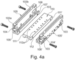
- Fig. 4a shows two side support modules 105, 105' of a pair of side support modules 100, 100a, 100b and a base support module 110 in an exploded view.
- Two end faces 106, 106 of the side support module 105 are shown at opposite ends (in the longitudinal direction) of the side support module 105, to which two end plates 120 (not shown) can be detachably mounted.
- An end plate and a side support module 105 of a further pair of side support modules 100a can also be detachably mounted/arranged on the end faces 106, 106.
- Two side support modules of two further pairs of side support modules 100a, 100b can also be arranged on the end faces 106, 106.
- the end faces are thus designed for at least two functions.
- the side support modules 105, 105' have second mounting means 103a on their end faces 106, 106' (in the figure only marked on one end face 106 of a side support element 105). These are designed for the detachable connection to the end plate. For the second function of the end faces 106, the end faces are designed to be flat so that they can be flush with one another.
- the U-shaped recesses 140, 140a are designed in such a way that they form a continuous end (without jumps) when side support modules are arranged in a row in the longitudinal direction.
- the side support modules 105, 105' are elongated and essentially form a U-shaped profile with legs of different lengths (the inward-facing leg is quite short).
- the smaller leg of each side support module ends with the inward-facing surface 107 essentially flush with the base support module 110, in particular with the surface 111, 111'.
- the two side support modules 105, 105' can be detachably mounted on the side surface 107 with the base support module 110 via the sides 111, 111'.
- the base support module 110 has first mounting means 112 on both sides 111, 111' arranged transversely to the conveying direction, which are designed for a force-fitting connection to the first mounting means 103 of the side support modules 105, 105'.
- the side support modules 105, 105' also have third mounting means 103b.
- a guide rail 130 ( Fig.5 ) can be detachably connected to a side support module 105.
- the third mounting means 103b are present in large numbers and thus enable flexible fastening of the guide rail.
- the guide rail 130 and the third mounting means 103b of the side support modules 105, 105' are designed such that the guide rail 130 can be connected simultaneously to several side support modules 105, 105' of pairs of side support modules 100, 100a, 100b arranged in the conveying direction ( Fig. 7a, 7b ).
- Fig. 4b shows Fig.4 in an exploded view.
- the figure shows a recess 122 of the end plate 120' along the conveying direction (the same applies to the end plate 120), which is arranged essentially in the middle of the end plate 120'.
- This recess 122 is designed to accommodate the conveying module (e.g. the carriage plate 140, holding device 150 and/or a magnetic rail 160) during operation of the feed (cf. Fig.5 , 8th ). This allows an increased travel length of the carriage plate.
- the figure also shows the connection of the second mounting means 103a on the end faces of the side support modules 105, 105' with the end plates 120.
- the connection can be made via pins and/or screws.
- Fig.5 shows the supporting structure Fig.4 with further components of a feed according to an embodiment of the present invention.
- a carriage plate 140 is shown (which is included in the conveyor module) which is designed to be moved between the two end plates 120, 120'.
- the carriage plate 140 is moved on and along the guide rails 130, 130' which are attached to the side support modules 105, 105' along the longitudinal direction of the pair of side support modules 100.
- the conveying direction F can be oriented in both directions shown by the arrows by the design of the feed components using the same feed components.
- the same support plate 180 ( Fig.6 ) can be detachably fastened to the right and left end plates 120, 120'.
- the support plates 180 and the end plate 120, 120' have fastening means that are congruent with one another in order to be able to detachably mount the components together.
- Fig.6 shows a feed 1 with the components from Fig.5 and with further components of a feed 1 according to an embodiment of the present invention. Three perspective views of the feed 1 are shown.
- FIG. 1 A view from below is shown at the top left of this figure, so that essentially a rear side of the feed can be seen.
- the visible surfaces of the base support module 110, the side support modules 105, 105', the end plates 120, 120' and the mounting feet 125 would essentially be on the floor.
- Four mounting feet 125 are shown, each of which protrudes vertically outwards from the two end plates 120, 120' and is detachably mounted on the end plates 120, 120'.
- FIG. 1 A similar perspective view from below is shown at the top right of this figure. This shows further optional side cover plates 126 and an optional upper cover plate 127. In addition, the support plate 180 comprising two guide rollers 181, 181' is shown.
- FIG. 1 a perspective sectional view of the plane A-A (marked at the top left in the figure) is shown.
- the drive unit 170 is laterally (sideways) limited by the side support modules 105, 105' and is detachably mounted on the base support module 110 (via second mounting means 112a of the base support module 110).
- the magnetic rail 160 is detachably mounted on the carriage plate 140.
- the mounting devices 150 are detachably mounted to the carriage plate (from above). Several optional mounting devices 150 are shown.
- the drive unit 170 When the feed 1 is in operation, the drive unit 170 is spatially fixed and drives the magnetic rail 160, which moves along the guide rails 130, 130' and thus also moves the carriage plate 140 and the mounting devices 150.
- the components that move together can be viewed as a conveyor module.
- the view according to the lower illustration of the feed 1 in this figure corresponds to a usual orientation when the feed is in operation.
- the conveyor directions F for the feed 1 are shown for this view.
- Fig.7 shows the support structure and the pair of side support modules 100 from Fig.4 with further components of a feed according to an embodiment of the present invention.
- Fig.4 Also shown here are the guide rails 130, 130', which are detachably connected to the pair of side support modules 100 or to the first 105 and the second 105' side support module, respectively.
- the pair of side support modules 100 constitutes a part of the U-shaped support structure.
- the side support modules 105, 105' are designed to form one or more feeds with different lengths by arranging one or more pairs of side support modules 100, 100a, 100b in a row. This is particularly evident in comparison to the Fig. 7, 7a and 7b shown.
- Fig. 7a shows the embodiments of Fig.7 , wherein a further pair of side support modules 100a according to an embodiment of the present invention is included.
- the side support modules 105, 105' are not separately identified in this figure, but only the pairs of side support modules 100, 100a.
- a plane S is indicated by the dashed square. Some of the components of the feed shown are symmetrical to the plane S. Likewise, the mounting means described here are at least partially symmetrical to the plane S. This applies, for example, to the first mounting means 103 of the side support modules 105, 105'.
- Fig. 7b shows the embodiments of Fig. 7a , wherein a further pair of side support modules 100b according to an embodiment of the present invention is included.
- the length Lo of the pair of side support modules (this corresponds to the length of one side support module) 100, 100a, 100b is equal, as described herein.
- Fig.7 therefore shows a feed with a length of approximately 130 mm.
- Fig. 7a shows a feed with a length of approximately 260 mm.
- Fig. 7b shows a feed with a length of approximately 390 mm.
- the end plates 120, 120' are in all versions Fig. 7, 7a and 7b similar (identical).
- the end plate 120 is by means of its front surface 121 (the reference number is in Fig.4 and 4b shown) with the end faces 106, 106' (the reference numerals are in Fig.3 and Fig. 4a shown) of the pair of side support modules 100b.
- the pair of side support modules 100b is attached to the inwardly directed side surfaces 107, 107' (the reference numerals are in Fig. 4a shown) detachably connected to the basic support module 110 (at a point perpendicular to the plane S, cf. Fig. 7a , facing surface 111, 111', the reference numerals are in Fig. 4a and Fig.6 shown) and arranged on the pair of side support modules 100a (on end faces 106, 106' of the pairs of side support modules 100b, 100a).
- the pair of side support modules 100a is detachably connected to the basic support module 110 (at a point perpendicular to the plane S, cf. Fig. 7a , facing surface 111, 111') and to the pair of side support modules 100 (on end faces 106, 106' of the pairs of side support modules 100a, 100).
- the pair of side support modules 100 is detachably connected to the Basic load-bearing module 110 (at a point perpendicular to plane S, cf. Fig. 7a , facing surface 111, 111') and with the end plate 120' (on end faces 106, 106' of the pair of side support modules 100). It is advantageous that in this way different feeds can be formed flexibly, quickly and cost-efficiently using similar components.
- two side support modules 105, 105' form a pair of side support modules 100, with the base support module 110 arranged in between.
- the pair of side support modules 105, 105' essentially forms a U-shaped support structure with the base support module 110 and offers stability of the feed.
- the side support modules 105, 105' are spaced apart in pairs by the single base support module 110 in between at right angles to the conveying direction and are arranged in rows along their longitudinal direction on end faces. Two rows are therefore formed.
- the rows (the first row formed from one, two or three of the side support module 105, the second row formed from one, two or three of the side support module 105') are detachably mounted to the base support module 110 as described herein.
- the basic support module 110 is designed as a single piece for each feed and has a length that matches the respective length of the support structure (1 ⁇ L0, 2 ⁇ L0, or 3 ⁇ L0). This increases the stability of the feed.
- the guide rails 130, 130' are in Fig. 7b not shown consistently. It is understood that the guide rails 130, 130' extend from the first 120 to the second 120' end plate and in some cases even contact them.
- Fig.8 shows the embodiments of Fig. 7b with further components of a feed according to an embodiment of the present invention.
- a carriage plate 140 is visible here, on which a movable holding device 150 is detachably mounted.
- the carriage plate 140 is arranged to be movable along the conveying direction F.
- a second movable holding device 150 is indicated in dashed lines, which can optionally be included in the feed.
- the second movable Holding device improves the guidance of strip material.
- the dashed movable holding device 150 also means that only a movable holding device is provided at the dashed position.
- the position in the longitudinal direction is flexible due to the carriage plate 140.
- the figure also shows a support plate 180 which is designed to be able to be attached to both end plates 120, 120'.
- An embodiment is shown in which the support plate 180 is arranged only at one end of the feed (right).
- the conveying direction F can be oriented in both directions shown by the arrows due to the structural design of the feed components using the same feed components. With the illustrated arrangement of the support plate 180, the conveying direction F is oriented to the left in the figure.
- the support plate 180 comprises two guide rollers 181, 181', which are designed to guide the strip material and feed it to the fixed holding device 150' and then to feed it to the movable holding device 150 fastened to the carriage plate 140 (and optionally to feed it to another movable holding device 150).
- Three similar magnetic rails 160, 160a, 160b are shown, which are attached to the carriage plate 140 adjacent to one another in the longitudinal direction (in the conveying direction F) and consequently move with the carriage plate 140.
- the carriage plate 140 is driven by a drive unit 170 (not shown in this figure).
- the drive unit 170 is arranged between two side support modules 105, 105' of a pair of side support modules 100, 100a, 100b and above the base support module 110 (facing from the web of the U-shaped profile of the support structure towards the opening of the U-shaped profile).
- the drive unit 170 is a linear motor.
- the electrical winding is usually spatially fixed and causes a movement of the magnetic rails 160, 160a, 160b (these can comprise a permanent magnet) through the flow of electrical current.
- an increased coverage area of drive unit 170 and magnetic rails in the conveying direction F can be achieved compared to conventional designs of feeders.
- the arrangement offers the advantage that the weight ratio of magnetic rails 160, 160a, 106b to the drive unit 170 is low and thus a small mass has to be accelerated.
- a cable tray may be provided to guide, for example, a power cable of the drive unit (the drive unit would move with each stroke in such cases).
- the width B0 of the end plate 120 (and the identical end plate 120') is approximately 70 mm to 150 mm, preferably 90 mm to 140 mm, further preferably 100 mm to 125 mm, most preferably 110 mm to 115 mm or even 112 mm.
- This width can also correspond to an installation width of the feeds. It is possible that the mounting feet 125 protrude laterally somewhat further beyond the width of the end plate 120.
- the width of the holding devices 150 is approximately 98 mm. However, wider holding devices 150 can also be provided, depending on the application.
- guide rails 130, 130' are not shown continuously in this figure. It is understood that the guide rails 130, 130' extend from the first 120 to the second 120' end plate and in some cases even contact them.
- the feed 1 can also comprise a roller basket which is designed such that it can be flexibly mounted on, for example, an end plate 180.
- the passage width of the holding devices 150, 150' is approximately 60 mm to 120 mm, preferably 65 mm to 95 mm, further preferably 70 mm to 90 mm, most preferably 75 mm to 85 mm or even 80 mm.
- Fig.9 shows a feed with two 100, 100a (left) and a feed with three 100, 100a, 100b (right) pairs of side support modules according to two embodiments of the present invention.
- the base support module 110 of the left embodiment has a length of 2 ⁇ L0
- the base support module 110 of the right embodiment has a length of 3 ⁇ L0.
- Fig.9 shows at least one conveyor module (comprising the carriage plate 140, the magnetic rails 160, 160a, 160b and the holding device 150) which is arranged on the U-shaped support structure so as to be movable in the conveying direction F.
- the holding device 150 is elongated, with the longitudinal axis of the holding device 150 running essentially parallel to the normal of the carriage plate 140.
- the magnetic rails 160, 160a, 160b are flat and are connected to the carriage plate 140 in such a way that their normals run essentially parallel (in the right-hand view, the normal points diagonally to the right towards the viewer).
- the end plate 120 of this embodiment is identical to the previously described end plates 120, 120'. Consequently, the width B0 of the end plate 120 in the embodiment shown in this figure (also referred to as the "rotated" embodiment) corresponds to a height.
- the dimension B0 shown in this figure corresponds to a second dimension which is substantially perpendicular to the normal of the carriage plate 140 and to the conveying direction F.
- the end plates 120 also have a first dimension along the normal of the carriage plate 140.
- the horizontal/lying versions of the feeds have a height (in Fig.8 vertically) from approximately 94 mm including the 150 mounting brackets (approximately 102 mm including the cover plates).
- the height of the end plate 120 is approximately 58 mm. This height also applies to a wider design of the horizontal/lying feeds (cf. Fig. 12 ).
- the width of the rotated embodiments is based on the heights of the horizontal/lying embodiments and is therefore significantly narrower than the width of the horizontal/lying embodiments.
- the height of the rotated embodiments (in Fig.9 measured in direction B0) is approximately 148 mm including retaining devices 150 (approximately 156 mm including cover plates).
- the previously described feeds are rotated by about 90° (or by about -90° or similar) and the holding devices 150, 150' are detachably mounted on a narrow side of the feed.
- the components of the feed are the same components of the other embodiments described herein due to their modular nature. This applies in particular to the pairs of side support modules 100, 100a, 100b, the base support module 110, the carriage plate 140, the end plate 120, the guide rail(s) 130, the magnetic rail(s) 160, the drive unit 170, and the guide carriages (not separately marked) that are guided on the guide rails 130, 130'. Consequently, the modular components can be produced in larger quantities and assembled flexibly.
- a further advantage of the rotated embodiment is that the feed can be attached to a wall using the lower surface of the base support module 110, the pair of side support modules 100, 100a, 100b, the end plates 120 and/or the mounting feet (in the left view of this figure the "lower surface” is visible).
- only holding devices 150 with a smaller passage width are used, for example in the range between approximately 20 mm to 60 mm, preferably 30 mm to 50 mm, further preferably 35 mm to 45 mm, most preferably 38 mm to 42 mm or even 40 mm.
- the holding devices are thus adapted to the intended feed application and favor the space advantage created by the rotation.
- the end plates 120, 120' have a large number of fastening holes. This facilitates the further Operation of the feed after rotation can be ensured in a simple manner.
- the carriage plate 140 and the movable holding device 150 are configured such that the holding device 150 is in a first orientation with an upper side of the carriage plate 140 (cf. Fig.8 ) and in a second orientation can be detachably connected to an outer side of the carriage plate 140 (cf. Fig.9 ).
- a gripper plate 190 can be included in the feed, which is detachably mounted to the carriage plate 140 and accommodates the holding device 150. Thus, no conversion of the carriage plate 140 is necessary.
- Fig.10 shows a feed with two drive units 170, 170' and two pairs of side support modules 100, 100a according to an embodiment of the present invention in a first position of the carriage plates (left) and a second position of the carriage plates (right).
- the basic support module 110 has a length of 2 ⁇ L0.
- the widths of the components in particular the end plate 120 and the holding devices 150, 150', what is described here applies to the Fig. 3 to 8 .
- the two conveyor modules each comprise one of the carriage plates 140, 140' (the are similar) and a holding device 150 (also similar), which are detachably connected to the respective carriage plates 140, 140'.
- two drive units 170, 170' are detachably mounted to the base support module 110 (not separately marked in the figure, but as described herein).
- magnetic rails 160, 160' are detachably mounted on each carriage plate 140, 140'.
- two independent measuring systems can also be installed.
- each carriage plate 140, 140' can be controlled individually and travel an individual path along the conveying direction F.
- the conveying process of strip material can be understood as follows: In an extended position (see right view), the first holding device 150 (in the right view this would be the left holding device 150) grips the strip material and is then moved translationally/linearly along the conveying direction F to approximately the middle of the feed 1 via the linear motor 170 (this position of the left holding device is shown in the left view). When it reaches the middle, the second holding device 150 grips, thus taking control of the strip material and is moved translationally via the linear motor 170' to the other side of the feed (in the views on the right).
- Fig. 11 shows a feed 1b, which is formed from two feeds 1, 1a arranged at the back of one another according to an embodiment of the present invention. A first position of the carriage plates (left) and a second position of the carriage plates (right) are shown.
- the two feeds 1, 1a which are arranged at the back of each other and are detachably mounted to one another, are identified in this figure by the reference numerals 1 and 1a and, when assembled, form the feed 1b.
- the basic support module 110 With regard to the pairs of side support modules 100, 100a, 100b of the conveying direction F, the basic support module 110, and with regard to the other components (even if not explicitly mentioned), what is described here applies, provided it is technically reasonable. It is also understood that an embodiment of a feed 1b with only one pair of side support modules 100 or with three 100, 100a, 100b pairs of side support modules is also possible and is covered by the invention. For reasons of clarity, some reference numerals have been omitted in the two views.
- the basic support module 110 of the embodiment has a length of 2 ⁇ L0. With regard to the widths of the components (in particular the end plate 120 and the holding devices 150, 150'), what is described here applies to the Fig. 3 to 8 .
- the feed 1b comprises a support structure which is formed along the conveying direction and a first and a second conveyor module (each conveyor module comprises a carriage plate 140, a holding device 150, and a gripper plate 190) which are arranged on the support structure so as to be movable in the conveying direction.
- the conveyor modules can at least partially overlap along the conveying direction (in the first position the conveyor modules overlap by approximately 50%, in the second position by a slightly smaller proportion. There are positions in which the conveyor modules overlap by 100%).
- Each feed 1, 1a contains an independent base support module 110. Consequently, the feed 1b contains two base support modules 110.
- the feed 1b also contains two carriage plates 140 (in the figure, only the front carriage plate 140 of the feed 1 is marked in the left view).
- the holding devices 150, 150' are, comparable to the rotated embodiment ( Fig.9 ) is detachably mounted on a narrow side of the feed. Due to the arrangement of the feed 1b, the carriage plates 140 do not interfere with each other in their respective travel paths. In this way, the holding devices 150, 150' can advantageously each move over a length of at least 40%, preferably at least 45%, most preferably at least 50% of the entire travel path (between the two end plates 120' and the two end plates 120).
- the version in Fig. 11 may be useful to provide a gripper plate 190 which is detachably mounted to the carriage plate 140.
- the conveying process of strip material/a workpiece is similar to that of the embodiment of Fig.10 to be understood. However, it is understood that a movable holding device 150, 150' can cover a larger travel path. This means that the material is guided more safely and evenly. It would be conceivable to design the carriage plate 140 in such a way that the movable holding devices 150, 150' can cover a larger travel path than 50% of the distance between the end plates. However, this is not necessary since the transfer of the strip material takes place at approximately 50% of the distance between the end plates (50% of the feed length).
- the support structures can be in contact over an area of at least 10%, 20% or more on the rear sides.
- the contact area can be 48.4% (if, for example, only one pair of side support modules is provided, 1 ⁇ L0 support structure length).
- Fig. 12 shows feeds 1, 1a, 1b of different lengths according to three embodiments of the present invention, wherein the embodiments are similar to Fig.8 Compared to the embodiment in Fig.8 The width of the feeds is changed.
- the feed 1 has a length of Lo (one pair of side support modules 100).
- the feed 1a has a length of 2 ⁇ L0 (two pairs of side support modules 100, 100a).
- the feed 1b has a length of 3 ⁇ L0 (three pairs of side support modules 100, 100a, 100b, only 100b is marked for reasons of clarity).
- the passage width of the holding devices 150, 150' is approximately 120 mm to 190 mm, preferably 130 mm to 190 mm, further preferably 140 mm to 180 mm, most preferably 150 mm to 170 mm or even 160 mm.
- the width B1 of the end plate 220 (and the identical end plate 220') is approximately 150 mm to 300 mm, preferably 170 mm to 250 mm, further preferably 180 mm to 200 mm, most preferably 190 mm to 195 mm, or even 192 mm.
- This width can also correspond to an installation width of the feeds 1, 1a, 1b. It is possible that the mounting feet 125 protrude laterally somewhat further beyond the width of the end plate 220.
- the side support modules 100, 100a, 100b used are of the same type as described herein and therefore correspond to those of the previous embodiments.
- the base support module 210 is adapted to the widening, the same applies to the magnetic rail 160 and the carriage plates 140.
- the carriage plates 140 of the Fig. 12 The three feeds 1, 1a, 1b shown are of the same type. The same applies to the magnetic rail of feed 1 and the three magnetic rails 160, 160a, 160b of feed 1b. This is made possible by the modular design of the components and reduces costs.
- the magnetic rail 160 of the feed 1a is more than twice as long as the magnetic rail 160 (whose length corresponds to that of the magnetic rails 160, 160a, 160b of the feed 1b due to the similarity) of the feed 1. In this way, an increased overlap between the drive unit 170 and the magnetic rail 160 can be achieved in the feed 1a during operation of the feed 1a.
- the modularity according to the invention makes it possible for two identical magnetic rails 160, 160a to be used in the feed 1a if desired.
- the drive units 170 are also identical in all three feeds and one drive unit 170 is used in all three feeds 1, 1a, 1b.
- the drive units 170 differ only in their width.
- Fig. 13 shows three feeds 1, 1a, 1b of different lengths according to three rotated embodiments of the present invention, wherein the embodiments are similar to Fig.9 are (accordingly, the description therein also applies to Fig. 13 ), but have a different height.
- the width B1 of the end plate 120 of the embodiments according to Fig. 12 corresponds in the rotated embodiment according to Fig. 13 a height as in Fig. 13 identified.
- the feed 1 has a length of Lo (one pair of side support modules 100).
- the feed 1a has a length of 2 ⁇ Lo (two pairs of side support modules 100, 100a).
- the feed 1b has a length of 3 ⁇ Lo (three pairs of side support modules 100, 100a, 100b). Due to the modularity, essentially the same components as in Fig. 12 for use.
- the passage width of the holding devices 150, 150' is approximately 60 mm to 120 mm, preferably 65 mm to 95 mm, further preferably 70 mm to 90 mm, most preferably 75 mm to 85 mm or even 80 mm.
- Fig. 14 shows two feeds 1, 1a of different lengths according to two embodiments of the present invention, wherein the embodiments are similar to Fig.10 are (accordingly, the description therein also applies to Fig. 14 ), but have a different width.
- the width B1 of the end plate 120 of the embodiments according to Fig. 14 corresponds to that of Fig. 12 (accordingly, the description therein also applies to Fig. 14 ).
- the feed 1 has a length of 2 ⁇ Lo (two pairs of side support modules 100, 100a).
- the feed 1a has a length of 3 ⁇ Lo (three pairs of side support modules 100, 100a, 100b, not separately marked for reasons of clarity).
- the feed 1 in Fig. 14 includes a magnetic plate 160 on each side.
- the feed 1a in Fig. 14 comprises two magnetic plates 160, 160a (also of the same type) on each side and has a connecting element 161 between the similar carriage plates 140.
- the connecting element 161 can be Spacers between the carriage plates 140.
- the connecting element 161 can detachably mount the two magnetic rails 160 and 160a together. In this way, the same magnetic plates 160, 160a can be used and no longer magnetic plate has to be used.
- the magnetic plates of the feeds 1, 1a correspond to the magnetic plates of the feeds 1, 1b from Fig. 13 and the feeds 1, 1b from Fig. 12 .
- Fig. 15 shows two feeds 1, 1a of different lengths according to two embodiments of the present invention, wherein the embodiments are similar to Fig. 11 are (accordingly, the description therein also applies to Fig. 15 ), but have a different width.
- the width B1 of the end plate 120 of the embodiments according to Fig. 15 corresponds to that of Fig. 12 (accordingly, the description therein also applies to Fig. 15 ).
- two feeds arranged one behind the other and detachably mounted to one another form the feed 1 and the feed 1a, respectively.
- the feed 1 has a length of 2 ⁇ Lo (two pairs of side support modules 100, 100a).
- the feed 1a has a length of 3 ⁇ Lo (three pairs of side support modules 100, 100a, 100b, not separately marked for reasons of clarity).
- the spacing of the carriage plates 140 in the conveying direction F can be made variable due to the universal mounting means of the carriage plates 140 and the magnetic rails 160, 160a, 160b (all of the same type). Consequently, the feed 1, 1a can be adapted to a wide range of feed applications.
- the holding devices 150, 150' are detachably mounted to the carriage plates 140 via gripper plates at the same axial height (along the conveying direction F) as the carriage plates 140. Consequently, a changed spacing of the carriage plates 140 requires a changed spacing of the holding devices 150, 150'.
- the distance between two holding devices 150, 150' that can move in the same direction can thus be adjusted variably, depending on the desired/permitted/allowed sagging of the strip material.
- Fig. 15 In contrast to the embodiment from Fig. 14 , is in Fig. 15 an example of an adjacent arrangement of the carriage plates 140 is shown.
- no connecting element 161 in Fig. 14 shown
- the Carriage plates 140 extend at least partially over all three magnetic plates in the conveying direction 160, 160a, 160b (over less than approximately half of the magnetic plate 160, over the entire magnetic plate 160a and over less than approximately half of the magnetic plate 160b). This enables a detachable assembly of all three magnetic plates 160, 160a, 160b by means of the two carriage plates 140.
- the magnetic rail 160 of the feed 1 is shown to be more than twice as long as the magnetic rail 160 (whose length corresponds to that of the magnetic rails 160a and 160b due to the similarity) of the feed 1a. In this way, an increased overlap between the drive unit 170 and the magnetic rail 160 can be achieved in the feed 1 during operation of the feed 1.
- the modularity according to the invention makes it possible for two similar magnetic rails 160, 160a to be used in the feed 1 if desired.
- R stands for embodiments in which a longitudinal axis of the holding device runs essentially parallel to the normal of the carriage plate (cf. in Fig.9 and 13 ).
- T stands for embodiments in which the conveyor modules are arranged on the support structure so that they can move independently of each other in the conveying direction (cf. in Fig.10 and 14 ).
- X stands for embodiments in which the conveyor modules are designed in such a way that they can at least partially overlap in the conveying direction (cf. in Fig. 11 and 15 ).
- A indicates a side support module of type A (all side support modules of type A are therefore identical).
- B indicates a different quality compared to “A”, for example the basic support module B is twice as long as the basic support module A.
- the designation “A ⁇ " means, for example, that the basic support module A ⁇ differs from the basic support module A only in the quality of the width.
- the designation “A ⁇ " means, for example, that the clamp A ⁇ differs from the clamp A and the clamp A ⁇ only in the quality of the width.
- the designation "160/240” means, for example, that the clamp passage width can be 160 mm or 240 mm.
- the side support modules 105, 105' can be designed in the same way.
- the feeds can also be referred to as gripper feeds.
- strip materials with a thickness of at least 0.05 mm and/or a maximum of 20 mm can be conveyed.
- strip materials with a thickness of 0.05 to 15 mm, more preferably from 0.05 mm to 10 mm, more preferably from 0.05 mm to 8 mm, most preferably from 0.1 mm to 5 mm can be conveyed. Adjustments can be made to the holding devices in order to convey thicker/thinner strip materials.
- the components preferably comprise metals as component materials.
- the materials of the base support module(s), side support module(s) and/or end plates are preferably aluminum, which in some cases can also be anodized.
- the holding devices also comprise aluminum, which ensures a low mass and promotes higher cycle rates.
- the holding devices also comprise steel for clamping plates of the holding devices, wherein the clamping plates come into contact with the strip material.
Landscapes
- Engineering & Computer Science (AREA)
- General Engineering & Computer Science (AREA)
- Mechanical Engineering (AREA)
- Feeding Of Articles To Conveyors (AREA)
- Framework For Endless Conveyors (AREA)
- Advancing Webs (AREA)
- Reciprocating Conveyors (AREA)
Priority Applications (3)
| Application Number | Priority Date | Filing Date | Title |
|---|---|---|---|
| EP22203035.5A EP4357044A1 (fr) | 2022-10-21 | 2022-10-21 | Avancement modulaire |
| EP25211894.8A EP4663964A3 (fr) | 2022-10-21 | 2022-10-21 | Avancement modulaire |
| US18/491,277 US20240228204A9 (en) | 2022-10-21 | 2023-10-20 | Modular feeder |
Applications Claiming Priority (1)
| Application Number | Priority Date | Filing Date | Title |
|---|---|---|---|
| EP22203035.5A EP4357044A1 (fr) | 2022-10-21 | 2022-10-21 | Avancement modulaire |
Related Child Applications (1)
| Application Number | Title | Priority Date | Filing Date |
|---|---|---|---|
| EP25211894.8A Division EP4663964A3 (fr) | 2022-10-21 | 2022-10-21 | Avancement modulaire |
Publications (1)
| Publication Number | Publication Date |
|---|---|
| EP4357044A1 true EP4357044A1 (fr) | 2024-04-24 |
Family
ID=83903404
Family Applications (2)
| Application Number | Title | Priority Date | Filing Date |
|---|---|---|---|
| EP25211894.8A Pending EP4663964A3 (fr) | 2022-10-21 | 2022-10-21 | Avancement modulaire |
| EP22203035.5A Withdrawn EP4357044A1 (fr) | 2022-10-21 | 2022-10-21 | Avancement modulaire |
Family Applications Before (1)
| Application Number | Title | Priority Date | Filing Date |
|---|---|---|---|
| EP25211894.8A Pending EP4663964A3 (fr) | 2022-10-21 | 2022-10-21 | Avancement modulaire |
Country Status (2)
| Country | Link |
|---|---|
| US (1) | US20240228204A9 (fr) |
| EP (2) | EP4663964A3 (fr) |
Citations (6)
| Publication number | Priority date | Publication date | Assignee | Title |
|---|---|---|---|---|
| GB703762A (en) * | 1950-12-18 | 1954-02-10 | Dexter & Co High Wycombe Ltd | Improvements in and relating to linear bearings |
| DE3629368A1 (de) * | 1986-08-29 | 1988-03-03 | Rixen Wolfgang | Profilstab |
| JPH02186107A (ja) * | 1989-01-09 | 1990-07-20 | T Echi K Kk | リニアアクチュエータ |
| US5505360A (en) * | 1993-11-30 | 1996-04-09 | Giusto; Placido | Movable gripping jaw with conveyor support for a web |
| CN108817248A (zh) * | 2018-07-09 | 2018-11-16 | 苏州市翔耀精密自动化设备有限公司 | 一种钢带送料装置 |
| US20220128089A1 (en) * | 2020-10-27 | 2022-04-28 | Nippon Thompson Co., Ltd. | Linear motion guide unit |
Family Cites Families (4)
| Publication number | Priority date | Publication date | Assignee | Title |
|---|---|---|---|---|
| DE2534914C3 (de) * | 1975-08-05 | 1978-05-24 | Siemens Ag, 1000 Berlin Und 8000 Muenchen | Taktvorschubgerät zum Zuführen von band- oder streifenförmigem Material |
| US4694982A (en) * | 1982-04-26 | 1987-09-22 | Pressmate, Inc. | Side by side air feeder for advancing stock to a power press and the like |
| US4925081A (en) * | 1989-04-17 | 1990-05-15 | J. V. Manufacturing Company, Inc. | Strip material feed guide |
| JP2002301530A (ja) * | 2001-04-04 | 2002-10-15 | Aishisu:Kk | 帯材を移動する装置 |
-
2022
- 2022-10-21 EP EP25211894.8A patent/EP4663964A3/fr active Pending
- 2022-10-21 EP EP22203035.5A patent/EP4357044A1/fr not_active Withdrawn
-
2023
- 2023-10-20 US US18/491,277 patent/US20240228204A9/en active Pending
Patent Citations (6)
| Publication number | Priority date | Publication date | Assignee | Title |
|---|---|---|---|---|
| GB703762A (en) * | 1950-12-18 | 1954-02-10 | Dexter & Co High Wycombe Ltd | Improvements in and relating to linear bearings |
| DE3629368A1 (de) * | 1986-08-29 | 1988-03-03 | Rixen Wolfgang | Profilstab |
| JPH02186107A (ja) * | 1989-01-09 | 1990-07-20 | T Echi K Kk | リニアアクチュエータ |
| US5505360A (en) * | 1993-11-30 | 1996-04-09 | Giusto; Placido | Movable gripping jaw with conveyor support for a web |
| CN108817248A (zh) * | 2018-07-09 | 2018-11-16 | 苏州市翔耀精密自动化设备有限公司 | 一种钢带送料装置 |
| US20220128089A1 (en) * | 2020-10-27 | 2022-04-28 | Nippon Thompson Co., Ltd. | Linear motion guide unit |
Also Published As
| Publication number | Publication date |
|---|---|
| EP4663964A2 (fr) | 2025-12-17 |
| US20240132310A1 (en) | 2024-04-25 |
| EP4663964A3 (fr) | 2026-02-18 |
| US20240228204A9 (en) | 2024-07-11 |
Similar Documents
| Publication | Publication Date | Title |
|---|---|---|
| AT392050B (de) | Fertigungsanlage mit mehreren einzelstationen | |
| DE19729369C5 (de) | Autarker Bearbeitungsplatz und daraus bestehende Bearbeitungsstraße | |
| AT512946B1 (de) | Fertigungsanlage zur Herstellung einer Baugruppe aus mehreren Teilen | |
| WO2009135641A1 (fr) | Machine d'usinage au laser avec espace de travail étendu | |
| EP2008734A1 (fr) | Dispositif de transport destiné au transport de pièces à usiner sur une machine de traitement | |
| DE112019001678B4 (de) | Förderpalette, palettenfördervorrichtung und palettenförderverfahren unter verwendung derselben | |
| EP3040296A1 (fr) | Systeme de transfert/montage modulaire | |
| EP1892423B1 (fr) | Dispositif d'entraînement linéaire doté de moyens de guidage pour charges lourdes | |
| EP4067272B1 (fr) | Système de transport | |
| WO2003066279A1 (fr) | Systeme de transport | |
| EP3075490B1 (fr) | Machine d'usinage | |
| AT404687B (de) | Anlage zur bearbeitung und/oder montage von bauteilen | |
| EP1990160A2 (fr) | Foreuse avec alimentation en continu | |
| AT505426B1 (de) | Verfahren zur herstellung eines trägers und träger | |
| EP2916994B1 (fr) | Installation de production d'un ensemble constitué de plusieurs éléments | |
| EP0830825A2 (fr) | Elément de liaison pour cadre de meuble, ensemble d'assemblage pour support de meuble et jeu de construction pour l'assemblage d'un meuble | |
| EP3028806A1 (fr) | Dispositif de traitement | |
| DE102013226826A1 (de) | Linearmotoranordnung und Werkzeugmaschine mit einer Linearmotoranordnung | |
| EP4357044A1 (fr) | Avancement modulaire | |
| DE19581466B4 (de) | Transferpresse | |
| EP0615405B1 (fr) | Système d'usinage et d'assemblage pour pièces de petites dimensions | |
| DE3238197C1 (de) | Selbsttätig gesteuerte Portalfräsmaschine | |
| EP1663564A1 (fr) | Pince porte-electrode | |
| DE19703240B4 (de) | Vorrichtung zum Handhaben und Bearbeiten von vorzugsweise plattenförmigen Werkstücken | |
| EP2397252B1 (fr) | Machine de traitement |
Legal Events
| Date | Code | Title | Description |
|---|---|---|---|
| PUAI | Public reference made under article 153(3) epc to a published international application that has entered the european phase |
Free format text: ORIGINAL CODE: 0009012 |
|
| STAA | Information on the status of an ep patent application or granted ep patent |
Free format text: STATUS: THE APPLICATION HAS BEEN PUBLISHED |
|
| AK | Designated contracting states |
Kind code of ref document: A1 Designated state(s): AL AT BE BG CH CY CZ DE DK EE ES FI FR GB GR HR HU IE IS IT LI LT LU LV MC ME MK MT NL NO PL PT RO RS SE SI SK SM TR |
|
| STAA | Information on the status of an ep patent application or granted ep patent |
Free format text: STATUS: REQUEST FOR EXAMINATION WAS MADE |
|
| 17P | Request for examination filed |
Effective date: 20240725 |
|
| RBV | Designated contracting states (corrected) |
Designated state(s): AL AT BE BG CH CY CZ DE DK EE ES FI FR GB GR HR HU IE IS IT LI LT LU LV MC ME MK MT NL NO PL PT RO RS SE SI SK SM TR |
|
| STAA | Information on the status of an ep patent application or granted ep patent |
Free format text: STATUS: THE APPLICATION HAS BEEN WITHDRAWN |
|
| 18W | Application withdrawn |
Effective date: 20251030 |