EP4357104A1 - Dispositif pour la fabrication de tubes en matière plastique - Google Patents
Dispositif pour la fabrication de tubes en matière plastique Download PDFInfo
- Publication number
- EP4357104A1 EP4357104A1 EP23204246.5A EP23204246A EP4357104A1 EP 4357104 A1 EP4357104 A1 EP 4357104A1 EP 23204246 A EP23204246 A EP 23204246A EP 4357104 A1 EP4357104 A1 EP 4357104A1
- Authority
- EP
- European Patent Office
- Prior art keywords
- guide
- mold
- guide pin
- section
- pins
- Prior art date
- Legal status (The legal status is an assumption and is not a legal conclusion. Google has not performed a legal analysis and makes no representation as to the accuracy of the status listed.)
- Pending
Links
Images








Classifications
-
- B—PERFORMING OPERATIONS; TRANSPORTING
- B29—WORKING OF PLASTICS; WORKING OF SUBSTANCES IN A PLASTIC STATE IN GENERAL
- B29C—SHAPING OR JOINING OF PLASTICS; SHAPING OF MATERIAL IN A PLASTIC STATE, NOT OTHERWISE PROVIDED FOR; AFTER-TREATMENT OF THE SHAPED PRODUCTS, e.g. REPAIRING
- B29C48/00—Extrusion moulding, i.e. expressing the moulding material through a die or nozzle which imparts the desired form; Apparatus therefor
- B29C48/03—Extrusion moulding, i.e. expressing the moulding material through a die or nozzle which imparts the desired form; Apparatus therefor characterised by the shape of the extruded material at extrusion
- B29C48/09—Articles with cross-sections having partially or fully enclosed cavities, e.g. pipes or channels
-
- B—PERFORMING OPERATIONS; TRANSPORTING
- B29—WORKING OF PLASTICS; WORKING OF SUBSTANCES IN A PLASTIC STATE IN GENERAL
- B29C—SHAPING OR JOINING OF PLASTICS; SHAPING OF MATERIAL IN A PLASTIC STATE, NOT OTHERWISE PROVIDED FOR; AFTER-TREATMENT OF THE SHAPED PRODUCTS, e.g. REPAIRING
- B29C48/00—Extrusion moulding, i.e. expressing the moulding material through a die or nozzle which imparts the desired form; Apparatus therefor
- B29C48/03—Extrusion moulding, i.e. expressing the moulding material through a die or nozzle which imparts the desired form; Apparatus therefor characterised by the shape of the extruded material at extrusion
- B29C48/13—Articles with a cross-section varying in the longitudinal direction, e.g. corrugated pipes
-
- B—PERFORMING OPERATIONS; TRANSPORTING
- B29—WORKING OF PLASTICS; WORKING OF SUBSTANCES IN A PLASTIC STATE IN GENERAL
- B29C—SHAPING OR JOINING OF PLASTICS; SHAPING OF MATERIAL IN A PLASTIC STATE, NOT OTHERWISE PROVIDED FOR; AFTER-TREATMENT OF THE SHAPED PRODUCTS, e.g. REPAIRING
- B29C48/00—Extrusion moulding, i.e. expressing the moulding material through a die or nozzle which imparts the desired form; Apparatus therefor
- B29C48/25—Component parts, details or accessories; Auxiliary operations
- B29C48/252—Drive or actuation means; Transmission means; Screw supporting means
- B29C48/2528—Drive or actuation means for non-plasticising purposes, e.g. dosing unit
-
- B—PERFORMING OPERATIONS; TRANSPORTING
- B29—WORKING OF PLASTICS; WORKING OF SUBSTANCES IN A PLASTIC STATE IN GENERAL
- B29C—SHAPING OR JOINING OF PLASTICS; SHAPING OF MATERIAL IN A PLASTIC STATE, NOT OTHERWISE PROVIDED FOR; AFTER-TREATMENT OF THE SHAPED PRODUCTS, e.g. REPAIRING
- B29C48/00—Extrusion moulding, i.e. expressing the moulding material through a die or nozzle which imparts the desired form; Apparatus therefor
- B29C48/25—Component parts, details or accessories; Auxiliary operations
- B29C48/256—Exchangeable extruder parts
- B29C48/2566—Die parts
-
- B—PERFORMING OPERATIONS; TRANSPORTING
- B29—WORKING OF PLASTICS; WORKING OF SUBSTANCES IN A PLASTIC STATE IN GENERAL
- B29C—SHAPING OR JOINING OF PLASTICS; SHAPING OF MATERIAL IN A PLASTIC STATE, NOT OTHERWISE PROVIDED FOR; AFTER-TREATMENT OF THE SHAPED PRODUCTS, e.g. REPAIRING
- B29C48/00—Extrusion moulding, i.e. expressing the moulding material through a die or nozzle which imparts the desired form; Apparatus therefor
- B29C48/25—Component parts, details or accessories; Auxiliary operations
- B29C48/30—Extrusion nozzles or dies
- B29C48/303—Extrusion nozzles or dies using dies or die parts movable in a closed circuit, e.g. mounted on movable endless support
-
- B—PERFORMING OPERATIONS; TRANSPORTING
- B29—WORKING OF PLASTICS; WORKING OF SUBSTANCES IN A PLASTIC STATE IN GENERAL
- B29C—SHAPING OR JOINING OF PLASTICS; SHAPING OF MATERIAL IN A PLASTIC STATE, NOT OTHERWISE PROVIDED FOR; AFTER-TREATMENT OF THE SHAPED PRODUCTS, e.g. REPAIRING
- B29C53/00—Shaping by bending, folding, twisting, straightening or flattening; Apparatus therefor
- B29C53/22—Corrugating
- B29C53/30—Corrugating of tubes
-
- B—PERFORMING OPERATIONS; TRANSPORTING
- B29—WORKING OF PLASTICS; WORKING OF SUBSTANCES IN A PLASTIC STATE IN GENERAL
- B29D—PRODUCING PARTICULAR ARTICLES FROM PLASTICS OR FROM SUBSTANCES IN A PLASTIC STATE
- B29D23/00—Producing tubular articles
- B29D23/18—Pleated or corrugated hoses
Definitions
- the invention relates to a device for producing plastic pipes, preferably plastic corrugated pipes according to the preamble of claim 1.
- the invention is based on the object of creating a device which is improved with regard to the guidance of the mold jaws.
- Preferred embodiments of alternative a) of the main claim provide that, in order to form an active position or inactive position according to alternative a), the additional guide pin or the additional guide pins engage or engage in the associated additional guide groove in that this guide pin or these guide pins engage or engage in a section of the associated guide groove in a form-fitting and/or force-fitting manner to form the active position and engage or engage or engage in a non-form-fitting and/or non-force-fitting manner in another section of the guide groove to form the inactive position.
- Particularly preferred embodiments of alternative a) of the main claim 1 can provide that in a first section of the guide device, preferably in the deflection area with adjoining inlet section, the first guide pin and the second guide pin are in the operative position, and the third guide pin and the fourth guide pin are in the inoperative position, and that in a second section of the guide device, preferably in the In the outlet section with subsequent deflection area, the third guide pin and the fourth guide pin are in the active position, and the first guide pin and the second guide pin are in the inactive position.
- preferred embodiments can provide that in order to form an inoperative position according to alternative a) and/or to form a non-positive and/or non-positive engagement according to alternative b), the guide groove into which the additional guide pin engages is designed as an extended guide groove whose clear width is larger than the diameter of the guide pin.
- Preferred embodiments can provide a resilient design of the guide grooves by providing that, in order to form an inoperative position according to alternative a) and/or to form a non-positive and/or non-positive engagement according to alternative b), the guide groove into which the additional guide pin engages has a resiliently mounted and/or resiliently designed side wall and/or has a resiliently mounted and/or resiliently designed groove base.
- the guide groove into which the additional guide pin engages is designed as a guide groove that widens in height.
- the guide pin can be designed to be resilient, in that it is provided that in order to form an inoperative position according to alternative a) and/or to form a non-positive and/or non-positive engagement according to alternative b), the additional guide pin is laterally resiliently mounted or laterally resilient.
- the additional guide pin is axially spring-mounted or designed to be axially spring-loaded.
- Particularly preferred embodiments, preferably according to alternative c) of the main claim 1 in the sense of a guide which supports forces of the additional further guide pin or the additional further guide pins which are directed differently than the forces supported in the guide groove of the first guide pin and/or the second guide pin, provide that the first guide pin and the second guide pin are formed on the upper side and/or on the lower side of the mold jaw, preferably aligned vertically, and that the additional further guide pin or the further guide pins are formed on the upper side and/or on the lower side of the mold jaw, preferably aligned vertically.
- first guide pin and the second guide pin each engage in the associated guide groove of the guide device while supporting lateral forces, preferably horizontally directed lateral forces of the guide pin, and that the additional further guide pin or the additional further guide pins engage or engage in the associated guide groove and/or interact or interact with the associated guide surface and/or guide edge of the guide device while supporting axial forces of the guide pin, preferably vertically directed axial forces.
- first guide pin and the second guide pin engage in the associated guide groove while supporting lateral forces of the guide pin, preferably horizontally directed lateral forces, and that the additional further guide pin or the additional further guide pins engage or engage in the associated guide groove for supporting lateral forces of the guide pin, preferably vertically directed lateral forces, and/or interact or interact with the associated guide surface or guide edge of the guide device.
- the guide pins are each designed such that the free end of the guide pin engaging in the guide groove is designed as a movement-resistant part of the guide pin.
- preferred embodiments can additionally or alternatively provide that the guide pins are each designed such that the guide pin is pressed or welded or screwed into the mold jaws.
- the guide grooves for engagement of the associated guide pins form at least a part of the stationary guide device for guiding the Forming mold jaws, preferably a guide device for a deflection area in the inlet section and/or a guide device for a deflection area in the outlet section and/or a guide device in the intermediate section of the corrugator in the region of the molding section for guiding the mold jaw pairs and/or in the region of the return for guiding the mold jaws and/or in the region of the return for guiding the mold jaws from the end of the molding section to the beginning of the molding section.
- the stationary guide device for guiding the mold jaws has a guide and/or tempering body device, which is preferably formed in the intermediate section of the corrugator in the region of the molding section for guiding the mold jaw pairs and/or in the region of the return for guiding the mold jaws from the end of the molding section to the beginning of the molding section.
- the guide and/or tempering body device is formed from a plurality of tempering bodies arranged axially one behind the other in the guide direction and/or is formed from a plurality of tempering bodies arranged next to one another transversely to the guide direction, wherein it is preferably provided that one or more tempering medium channel or channels are formed in the tempering body and/or in the tempering bodies, through which a tempering medium flows.
- guide recesses and/or flat guide surfaces having elevations and/or depressions are formed in a guide and tempering surface device, which interact with corresponding guide recesses and/or guide surfaces of the passing mold jaws.
- the left mold jaws are guided endlessly in a left mold jaw circuit and the right mold jaws are guided endlessly in a right mold jaw circuit, wherein the left mold jaw circuit and the right mold jaw circuit each have a deflection area, an inlet section designed as a deflection area with a deflection pinion device, a linear mold section and an outlet section designed as a deflection area with a deflection pinion device and a return section connecting the outlet section and the inlet section.
- the stationary guide device of the mold jaws is formed by a stationary guide device in each deflection region and by a stationary guide device in the intermediate section, wherein it is preferably provided that the stationary guide device in each deflection region has a frame device and/or a base plate device and/or a cover plate device on or in which the guide grooves are arranged and which has a guide surface device for slidingly guiding the underside of the passing mold jaws; and that the stationary guide device in the intermediate section has a guide and/or tempering body device which at least partially surrounds the passing mold jaws and has guide and/or tempering surfaces for sliding guidance with the outer surfaces of the mold jaws.
- the guide and/or tempering body device has a plurality of guide grooves which form the guide grooves for engagement of the guide pins of the mold jaws, wherein it is preferably provided that at least one of the guide grooves is formed by a gap between adjacent guide and/or tempering bodies.
- the tooth row device interacts with a deflection pinion device in the deflection areas.
- the tooth device additionally or alternatively interacts with a pinion device in the intermediate section, preferably in the mold section.
- Preferred designs provide that a tooth row device is formed on a side surface of each mold jaw, which interacts with the deflection pinion device in the deflection areas.
- the tooth row device has one or more internal or external rows of teeth which extend on a side surface of the mold jaw facing away from the mold surface of the mold jaw in the longitudinal direction of the mold jaw, i.e. in the production direction.
- the tooth row device in conjunction with the interacting pinion device i.e. the deflection pinion device in the deflection areas of the corrugator or another pinion device, e.g. in the forming section in the intermediate section of the corrugator, primarily has a drive function or play compensation function in the drive direction. It preferably has no guide function in the vertical direction, i.e. it does not act to absorb vertical forces.
- the pinion In designs in which the tooth row device is designed as an internal tooth row device and primarily has a drive function or a play compensation function in the drive direction, the pinion therefore engages in the tooth row device with upper and lower vertical play.
- the mold jaws are guided in the deflection areas by the guide pins on the mold jaws, which engage in fixed guide grooves in the deflection area.
- the guide pins only act laterally, ie they only absorb lateral forces.
- the mold jaws are guided in a vertical direction by supporting the underside of the mold jaws on a stationary guide surface, preferably a base surface of a stationary bearing and/or guide frame. In preferred designs, there is no axial vertical support in the guide grooves by the guide pins.
- the guide pins engage in the guide grooves with axial vertical play.
- the stationary guide device of the mold jaws in the intermediate section of the corrugator is designed as a guide and/or tempering body device.
- the mold jaws are guided at least on the underside of the mold jaws and optionally on at least one side surface of the mold jaws on guide and/or tempering surfaces of the guide and/or tempering body device.
- the guide pins on the underside and the top of the mold jaws engage in corresponding receiving grooves in the guide and/or tempering surfaces.
- the receiving grooves can be designed as guide grooves to support lateral forces. However, they can also be designed as receiving grooves with lateral play.
- Designs with a toothed row device on top require a receiving groove in the lateral guide and/or tempering surface of the guide and/or tempering body device, which in preferred designs is designed with upper and lower vertical play, so that the receiving groove does not have to provide a guiding function, ie no support of vertical forces.
- the guide pins can be automatically extended and retracted so that the lower guide and/or tempering surfaces of the guide and/or tempering body device can be designed as continuous surfaces without a receiving groove for the guide pins of the mold jaws.
- the top of the mold jaws runs with vertical clearance to the facing upper guide and/or tempering surface of the guide and/or tempering body device.
- These upper guide and/or tempering surfaces then have no guide function, but rather function merely as tempering surfaces.
- the tooth row device is designed as an internal tooth row device, which is formed by an internal tooth row or several internal tooth rows, wherein the teeth and/or the tooth gaps of the tooth row are each directed perpendicular to the side surface and into the side surface and are designed to engage and not protrude beyond the side surface, or that the tooth row device is designed as a resting tooth row device which is formed by a resting row of teeth or several resting rows of teeth, wherein the teeth and/or tooth gaps of the row of teeth are each directed perpendicular to the side surface and are designed to rest on the side surface and protrude beyond the side surface.
- the tooth row device designed as an internal tooth row device is formed by an internal tooth row arranged centrally or almost centrally with respect to the vertical extension of the side surface, or that the tooth row device designed as a resting tooth row device is formed by an overlying tooth row arranged centrally or almost centrally with respect to the vertical extension of the side surface.
- the central design of the row of teeth offers particular advantages with regard to the symmetrical introduction of force through the pinion meshing with the row of teeth.
- the tooth row device designed as an internal tooth row device is formed by an upper internal tooth row formed in the region of the upper half of the side surface, preferably directly in the upper edge of the mold jaw, and by a lower internal tooth row formed in the region of the lower half of the side surface, preferably directly in the lower edge of the mold jaw, or that the tooth row device designed as a resting tooth row device is formed by an upper resting tooth row formed in the region of the upper half of the side surface, preferably directly in the upper edge of the mold jaw, and by a lower internal tooth row formed in the region of the lower half of the side surface, preferably directly in the lower edge of the mold jaw, formed lower supporting row of teeth, wherein it is provided that the supporting row of teeth projects vertically from the side surface and the upper side of the supporting row of teeth is aligned with the upper side of the mold jaw and the lower side of the supporting row of teeth is aligned with the lower side of the mold jaw.
- the upper inner row of teeth is arranged at a distance below the upper edge of the side surface and/or the upper edge of the mold jaw, wherein the distance preferably corresponds to a quarter of the vertical extension of the side surface, and/or that the lower inner row of teeth is arranged at a distance above the lower edge of the side surface and/or the lower edge of the mold jaw, wherein the distance preferably corresponds to a quarter of the vertical extension of the side surface.
- An advantageous heat distribution in mould jaws with an internal tooth row device contributes to the provision that the internal tooth row of the tooth row device designed as an internal tooth row device has a tooth engaging in the side surface of the mould jaw engagement depth and the mold jaw has a minimum wall thickness between the outside of the side surface of the mold jaw and the mold surface of the mold jaw in the area of the smallest wall thickness of the mold jaw, where: d - t ⁇ t.
- the tooth row device is distributed asymmetrically on the side surface of the mold jaw with respect to the height of the side surface, and that the number of guide pins on the top of the mold jaw is different or the same as the number of guide pins on the bottom of the mold jaw, wherein each mold jaw has exactly two guide pins or exactly three guide pins or more than three guide pins.
- the width of the tooth row of the tooth row device extends transversely to the production direction at least over a third of the height of the mold jaw, preferably over half the height of the mold jaw, in particular over the entire height of the mold jaw, and that the number of guide pins on the top of the mold jaw is different or the same as the number of guide pins on the bottom of the mold jaw, wherein each mold jaw has exactly two guide pins or exactly three guide pins or more than three guide pins.
- the number of guide pins on the upper side of the mold jaws differs is the number of guide pins on the underside of the mold jaw, whereby each mold jaw has exactly two guide pins or exactly three guide pins or more than three guide pins.
- the embodiments each involve a device for producing plastic pipes.
- the general structure of the device is shown in the Figures 1 and 1a
- the device comprises an extruder 9 with an injection head 9s and a corrugator 1.
- a plastic melt hose is introduced into the corrugator 1 via the injection head 9s for forming a plastic tube 10.
- the corrugator 1 works with left and right mold jaws 5. It has a molding section 1f in which the left and right mold jaws 5 are guided as mold jaw pairs in the production direction.
- the left and right mold jaws 5 are brought together to form pairs of mold jaws at the beginning of the molding section 1f.
- the left and right mold jaws 5 of the mold jaw pairs are guided apart from the end of the molding section 1f.
- the molding section 1f is formed in an intermediate section 1z of the corrugator arranged between the inlet section 1e and the outlet section 1a. Furthermore, a return 1r is formed in the intermediate section 1z on both sides of the molding section 1f, namely a return 1r for the left mold jaws 5 and a return 1r for the right mold jaws 5. In these return 1r, the left and right mold jaws 5 are returned from the end of the molding section 1f to the beginning of the molding section 1f.
- the pairs of mold jaws arranged one behind the other in the mold section 1f lie abutting against one another in the mold section 1f.
- a pair of mold jaws comprises two mirror-image mold jaws 5, namely a left and a right mold jaw 5, whose mold surfaces 5f form the negative mold for the plastic pipe 10 formed in the device.
- the mold surfaces 5f are wave-shaped.
- the mold surfaces 5f of the pairs of mold jaws arranged abutting against one another in the mold section 1f form a continuous mold channel.
- the left mold jaws and the right mold jaws are each continuously moved in a self-contained mold jaw circuit.
- the left mold jaws are moved in the left mold jaw circuit and the right mold jaws are moved in the right mold jaw circuit.
- the two mold jaw circuits each have an essentially elliptical shape.
- Each mold jaw circuit consists of a straight section which forms the mold section 1f, a section leading into the mold section which forms the inlet section 1e and a Forming section leading out section, which forms the outlet section 1a, and a preferably straight return section, which forms the return 1r and represents the connection between the outlet section 1a and the inlet section 1e.
- the inlet section 1e and the outlet section 1a are each deflection regions in which deflection pinions 11 are arranged, which interact with tooth row devices 5z of the mold jaws guided in the deflection regions.
- the left mold jaw circuit and the right mold jaw circuit are arranged relative to one another such that the mold section 1f of the left mold jaw circuit and the mold section 1f of the right mold jaw circuit lie parallel to one another and the left and right mold jaws in the mold jaw section are arranged as mold jaw pairs with mold surfaces 5f facing one another.
- the nozzle-shaped injection head 9s of the extruder 9 is arranged with its outlet opening at the entrance of the molding section 1f.
- the plastic melt tube is injected into the molding section 1f of the corrugator via the injection head 9s.
- the pressures acting on the inside and outside of the plastic melt tube in the molding section 1f are controlled by appropriate pressure control.
- single- or multi-walled plastic tubes can be produced.
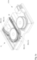
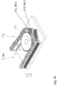
- the guide device 6u in the deflection areas of the corrugator is in the illustrated embodiment of the Figure 1 formed by guide pins formed on the mold jaws 5, which engage in fixed guide grooves in the fixed guide frame.
- the design of the guide pins and the associated guide grooves is explained in more detail below in section 2.
- the guide pins 5i are guided laterally in the guide grooves, i.e. with support from lateral forces.
- the mold jaws 5 are guided with their guide surfaces on the underside with vertical weight support on a horizontal support surface fixed to the frame.
- the support surface fixed to the frame can be designed to be flush with the upper edge of the guide groove adjacent to the guide grooves.
- the guide device 6z in the intermediate section of the corrugator is formed by a guide and/or tempering body device 8.
- a guide and/or tempering body device 8 This is in Fig.1 It has a guide and/or tempering surface device with guide recesses having elevations or depressions and/or flat guide surfaces, which interact with corresponding guide recesses and/or guide surfaces of the passing mold jaws.
- Tempering channels 8k are preferably formed in the tempering bodies 8i, through which tempering medium flows.
- the guide and/or tempering body device 8 is formed by guide and/or tempering bodies 8i.
- the guide and/or tempering bodies 8i are designed as elongated bodies with a longitudinal extension in the direction of production.
- Longitudinal tempering channels 8k are formed through which a tempering medium flows. They lie one behind the other in the longitudinal direction and one on top of the other in the transverse direction and form a receiving space for the passing mold jaws or pairs of mold jaws.
- the passing mold jaw pairs are surrounded on four sides by the guide and/or tempering bodies 8i in the embodiment shown.
- the passing mold jaws are surrounded on three sides.
- the surfaces of the guide and/or tempering bodies 8i facing the pairs of mold jaws or mold jaws form guide and/or tempering surfaces 8f on which the passing mold jaws are guided in a sliding manner, resting directly on them, or slide past them at a small distance.
- the directly resting sliding guidance takes place on the underside and, if necessary, on a side surface of the mold jaws.
- the sliding past at a small distance takes place on the top side of the mold jaws.
- guide grooves are formed in the guide and/or tempering body device 8 for receiving and guiding the guide pins formed on the mold jaws.
- the guide grooves in the guide and/or tempering bodies 8i are formed by longitudinal groove-shaped spaces being formed between adjacent guide and/or tempering bodies 8i. In modified designs, however, they can also be formed by longitudinal grooves. which can be formed in the individual guide and/or tempering bodies.
- stationary guide and/or tempering bodies 8i can also be arranged in the guide device 6u of the deflection areas, into which the guide pins 5i formed in the mold jaws engage to guide the mold jaws and additionally tempering takes place via the guide and/or tempering surfaces of the guide and/or tempering bodies.
- the guide pins formed on the mold jaws 5 can also engage in guide grooves in the stationary guide frame in the guide device 6z in the intermediate section of the corrugator.
- These can be guide grooves that are formed in or on the stationary guide and/or tempering bodies 8i and/or guide grooves that are formed in the guide frame outside the guide and/or tempering bodies 8i.
- the guide grooves in the guide and/or tempering body device 8 can interact with the guide pins in the sense of a sliding guide. However, they can also be designed with play to the guide pins and only accommodate the guide pins when the mold jaws pass through the guide and/or tempering body device 8.
- the sliding guide between the mold jaws and the guide and/or tempering body device can be designed between the outer surfaces of the mold jaws and the guide surfaces of the guide and/or tempering bodies.
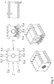
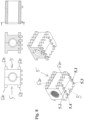
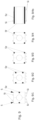
- the preferred mold jaws 5 are shown in the Figures 2 to 8 These mold jaws each have four guide pins 5i.
- the guide pins 5i are designated in the figures with 5.1, 5.2, 5.3 and 5.4.
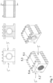
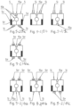
- the mold jaws 5 in the Figures 9 and 10 are modifications. They each have only three guide pins 5i. In these figures, the guide pins are designated 5i.
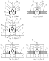
- the associated guide grooves 50i, in which the guide pins engage, are designated 50.1, 50.2, 50.3 and 50.4 in the figures.
- claim 1 is implemented as follows: In the deflection area that leads to the inlet into the mold section 1f , only the guide pins 5.1 and 5.2 are effective for guiding the mold jaws by engaging positively and/or non-positively in the associated guide grooves 50.1 and 50.2. The guide pins 5.3 and 5.4 are not effective during this phase, namely by measures that eliminate and/or significantly reduce a positive and/or non-positive engagement for the guidance of these guide pins 5.3 and 5.4, e.g. by implementing the measures of subclaims 3 to 7 there.
- the guide pins 5.3 and 5.4 are effective for guiding the mold jaws, engaging in a form-fitting and force-fitting manner in the associated guide grooves 50.3 and 50.4, ie in the operative position.
- the guide pins 5.1 and 5.2 are not effective in this area during this phase, ie in the ineffective position, by implementing measures which eliminate and/or at least significantly reduce a positive and/or non-positive engagement for this guidance of these guide pins 5.1 and 5.2, e.g. by measures of subclaims 3 to 7.
- the guide pins 5.1 and 5.2 effective in the inlet continue to be effective and the guide pins 5.3 and 5.4 are ineffective; while in the return area 1r the guide pins 5.3 and 5.4 effective in the outlet are effective and the guide pins 5.1 and 5.2 are ineffective.
- the guide pins are effective in the mold section 1f or in the return line 1r, but rather only the guide and/or tempering surfaces of the guide and/or tempering body device 8 interact with the mold jaws in the sense of a guide.
- the guide pins can engage in groove-shaped recesses with play, i.e. they do not engage in a force-fitting or form-fitting manner.
- the illustrated embodiments can also be modified in such a way that claim 1, alternative c) is implemented.
- the implementation of these designs with parallel redundant guides means a relatively high technical Standard. In order to implement parallel redundant guides, blocking situations due to overdetermination must be prevented. In order to implement parallel redundant guides permanently, it can be advantageous if the positive and/or non-positive engagement of the guide pins is reduced to a certain extent, i.e. to a certain degree, in all guides by implementing measures from subclaims 3 to 7.
- this reduction can be carried out as evenly as possible for all guides and to as small an extent as possible in order to implement the parallel redundant guides for all guide pins in their associated guide grooves as optimally as possible, as is the case with the embodiments according to claim 1, alternative c).
- Each mold jaw 5 has a total of four guide pins 5i, namely the guide pins 5.1, 5.2, 5.3 and 5.4. At least two of the guide pins are offset from each other in the direction of production in order to maintain the pivoting movement of the mold jaw in the deflection area.
- the mold jaws have a different number of guide pins 5i, ie in contrast to the Figures 2 to 8 illustrated embodiments, e.g. each mold jaw only has a total of three guide pins or each mold jaw has a total of more than four guide pins.
- FIGS 9 and 10 show such embodiments with a total of three guide pins 5i on the mold jaws 5.
- two guide pins are arranged on the underside and only one guide pin on the top of the mold jaw.
- the embodiment of the Fig.9 / 4 differs in the arrangement of the guide pins from the embodiment of the Fig.9 / 3 in that in Fig.9 / 4 the two guide pins 5i arranged on the underside of the mold jaws are arranged one behind the other in a common vertical plane in the direction of production.
- alternatives a, b and c of the main claim 1 can be implemented.
- different guide pins 5i are effective and ineffective.
- the upper guide pin 5i is referred to as the first guide pin
- the lower outer guide pin as the second guide pin
- the lower inner guide pin as the third guide pin.
- the first guide pin and the second guide pin it is then possible for the first guide pin and the second guide pin to be effective in the deflection area of the inlet section, while the third guide pin is ineffective. In the deflection area of the run-up section, the first guide pin and the third guide pin are then effective, while the second guide pin is ineffective.
- first guide pin and the second guide pin are permanently guided in a form-fitting and/or force-fitting manner in the associated guide grooves and the third guide pin is permanently redundantly guided in a form-fitting and/or force-fitting manner in the associated guide groove.
- Figures 9 and 10 illustrated embodiments have a tooth row device 5z, which differs from the tooth row device 5z of the Figures 2 to 8 The examples shown differ.
- Figures 2 to 8 the illustrated tooth row devices 5z are designed as overlying tooth row devices, each with a row of teeth formed on the upper edge of the mold jaw and a row of teeth formed on the lower edge of the mold jaw.
- the tooth row devices 5z are designed as internal tooth row devices 5z, as follows: In the example in Fig.9 / 1 the tooth row device 5z is formed by an inner row of teeth arranged centrally on the side surface.
- the tooth row device 5z on the side surface of the mold jaw is formed by an inner row of teeth formed in the region of the upper edge and an inner row of teeth formed in the region of the lower edge, wherein the respective rows of teeth are not formed directly in the edge, ie not directly in the upper edge or in the lower edge, but at a distance from the respective edge.
- the tooth row device 5z is formed by an upper row of teeth formed directly in the upper edge and a lower row of teeth formed directly in the lower edge.
- the tooth row device 5z is in contrast to the tooth row device of the embodiment of the Figure 9 not designed as an internal tooth row device, but as a surface-mounted tooth row device.
- the designs of the mold jaws can be identical to those in Fig.9 be.
Landscapes
- Engineering & Computer Science (AREA)
- Mechanical Engineering (AREA)
- Manufacturing & Machinery (AREA)
- Moulds For Moulding Plastics Or The Like (AREA)
Applications Claiming Priority (4)
| Application Number | Priority Date | Filing Date | Title |
|---|---|---|---|
| DE102022127261 | 2022-10-18 | ||
| DE102023102683.6A DE102023102683A1 (de) | 2022-10-18 | 2023-02-03 | Vorrichtung zum Herstellen von Kunststoffrohren |
| DE102023102686 | 2023-02-03 | ||
| DE102023120768.7A DE102023120768A1 (de) | 2023-02-03 | 2023-08-04 | Vorrichtung zum Herstellen von Kunststoffrohren |
Publications (1)
| Publication Number | Publication Date |
|---|---|
| EP4357104A1 true EP4357104A1 (fr) | 2024-04-24 |
Family
ID=88417149
Family Applications (2)
| Application Number | Title | Priority Date | Filing Date |
|---|---|---|---|
| EP23204246.5A Pending EP4357104A1 (fr) | 2022-10-18 | 2023-10-18 | Dispositif pour la fabrication de tubes en matière plastique |
| EP23204322.4A Withdrawn EP4357105A1 (fr) | 2022-10-18 | 2023-10-18 | Dispositif pour la fabrication de tubes en matière plastique |
Family Applications After (1)
| Application Number | Title | Priority Date | Filing Date |
|---|---|---|---|
| EP23204322.4A Withdrawn EP4357105A1 (fr) | 2022-10-18 | 2023-10-18 | Dispositif pour la fabrication de tubes en matière plastique |
Country Status (1)
| Country | Link |
|---|---|
| EP (2) | EP4357104A1 (fr) |
Citations (4)
| Publication number | Priority date | Publication date | Assignee | Title |
|---|---|---|---|---|
| US4504206A (en) * | 1982-01-21 | 1985-03-12 | Lupke Manfred Arno Alfred | Chainless mold drive for a corrugator or the like |
| DE102015115828A1 (de) * | 2015-09-18 | 2017-03-23 | Unicor Gmbh | Vorrichtung zum Herstellen von Kunststoffrohren |
| WO2017064368A1 (fr) | 2015-10-12 | 2017-04-20 | Nokia Technologies Oy | Capture et mixage audio distribué |
| WO2017168224A1 (fr) * | 2016-03-29 | 2017-10-05 | Itib Machinery International S.R.L. | Machine pour la production en continu d'un tube ondulé |
Family Cites Families (3)
| Publication number | Priority date | Publication date | Assignee | Title |
|---|---|---|---|---|
| DE19922726A1 (de) * | 1999-05-18 | 2000-11-23 | Ralph Peter Hegler | Vorrichtung zur Herstellung von Kunststoff-Wellrohren |
| DE202008017832U1 (de) * | 2008-04-28 | 2010-09-23 | Maintools Gmbh & Co.Kg | Formvorrichtung, insbesondere Corrugator, zum Herstellen von profilierten Kunststoffrohren |
| IT202200001310A1 (it) * | 2022-01-26 | 2023-07-26 | Itib Machinery Int S R L | Semi-stampo per una macchina per la produzione in continuo di tubo corrugato |
-
2023
- 2023-10-18 EP EP23204246.5A patent/EP4357104A1/fr active Pending
- 2023-10-18 EP EP23204322.4A patent/EP4357105A1/fr not_active Withdrawn
Patent Citations (5)
| Publication number | Priority date | Publication date | Assignee | Title |
|---|---|---|---|---|
| US4504206A (en) * | 1982-01-21 | 1985-03-12 | Lupke Manfred Arno Alfred | Chainless mold drive for a corrugator or the like |
| DE102015115828A1 (de) * | 2015-09-18 | 2017-03-23 | Unicor Gmbh | Vorrichtung zum Herstellen von Kunststoffrohren |
| WO2017046421A1 (fr) | 2015-09-18 | 2017-03-23 | Unicor Gmbh | Dispositif de fabrication de tuyaux en plastique |
| WO2017064368A1 (fr) | 2015-10-12 | 2017-04-20 | Nokia Technologies Oy | Capture et mixage audio distribué |
| WO2017168224A1 (fr) * | 2016-03-29 | 2017-10-05 | Itib Machinery International S.R.L. | Machine pour la production en continu d'un tube ondulé |
Also Published As
| Publication number | Publication date |
|---|---|
| EP4357105A1 (fr) | 2024-04-24 |
Similar Documents
| Publication | Publication Date | Title |
|---|---|---|
| DE102007028151B4 (de) | Ventilnadel-Betätigungseinheit für eine Heißläufervorrichtung | |
| WO2007121714A1 (fr) | Chaîne d'acheminement d'énergie | |
| EP0722820A1 (fr) | Dispositif de fermeture de moule sans colonnes | |
| EP3349961B1 (fr) | Dispositif de fabrication de tuyaux en plastique | |
| EP0580984B1 (fr) | Dispositif pour la fabrication d'un tuyau à parois ondulées | |
| DE102009002871B4 (de) | Hebeeinrichtung einer Druckmaschine und ein Verfahren zur Veränderung einer Breite einer Hebeeinrichtung | |
| DE102009023581A1 (de) | Presse, insbesondere kontinuierlich arbeitende Presse zur Herstellung von Werkstoffplatten | |
| EP4357104A1 (fr) | Dispositif pour la fabrication de tubes en matière plastique | |
| EP1239998B1 (fr) | Systeme distributeur pour canaux chauffants | |
| EP3275639B1 (fr) | Tampon pour une presse rotative | |
| DE102023102683A1 (de) | Vorrichtung zum Herstellen von Kunststoffrohren | |
| EP3349962B2 (fr) | Dispositif de fabrication de tuyaux en plastique | |
| DE3038160A1 (de) | Spritzgussvorrichtung | |
| EP1877233B1 (fr) | Dispositif pour separer un boudin d'argile plastique au moyen d'un dispositif d'entaille agissant sur tous les cotes | |
| EP4404755B1 (fr) | Dispositif de plaque de cuisson, four de cuisson et plaque de cuisson | |
| DE102023120768A1 (de) | Vorrichtung zum Herstellen von Kunststoffrohren | |
| WO2024213668A1 (fr) | Chaîne énergétique dotée de bandes de séparation | |
| EP3738693B1 (fr) | Machine de coulée sous pression pourvue de cadre d'énergie | |
| DE2509872A1 (de) | Stuetz- und kuehlvorrichtung fuer stranggiessprodukte | |
| DE3002039A1 (de) | Stehende hydraulische gesenkpresse | |
| DE4337342A1 (de) | Vorrichtung zum Kühlen von Walzbändern | |
| DE102005035247A1 (de) | Fluidverteiler mit binärer Struktur | |
| DE1808333A1 (de) | Auflaufrollgang fuer Kuehlbetten in Stabstahlwalzwerken | |
| EP3859176B1 (fr) | Rail télescopique | |
| DE102010055837A1 (de) | Vorrichtung zur Bildung von Zigarettengruppen |
Legal Events
| Date | Code | Title | Description |
|---|---|---|---|
| PUAI | Public reference made under article 153(3) epc to a published international application that has entered the european phase |
Free format text: ORIGINAL CODE: 0009012 |
|
| STAA | Information on the status of an ep patent application or granted ep patent |
Free format text: STATUS: THE APPLICATION HAS BEEN PUBLISHED |
|
| AK | Designated contracting states |
Kind code of ref document: A1 Designated state(s): AL AT BE BG CH CY CZ DE DK EE ES FI FR GB GR HR HU IE IS IT LI LT LU LV MC ME MK MT NL NO PL PT RO RS SE SI SK SM TR |
|
| STAA | Information on the status of an ep patent application or granted ep patent |
Free format text: STATUS: REQUEST FOR EXAMINATION WAS MADE |
|
| 17P | Request for examination filed |
Effective date: 20241024 |
|
| RBV | Designated contracting states (corrected) |
Designated state(s): AL AT BE BG CH CY CZ DE DK EE ES FI FR GB GR HR HU IE IS IT LI LT LU LV MC ME MK MT NL NO PL PT RO RS SE SI SK SM TR |
|
| RAP3 | Party data changed (applicant data changed or rights of an application transferred) |
Owner name: UNICOR GMBH |