EP4357213B1 - Procédé pour déterminer si une manoeuvre de direction d'évitement de collision automatique doit être exécutée ou non - Google Patents
Procédé pour déterminer si une manoeuvre de direction d'évitement de collision automatique doit être exécutée ou non Download PDFInfo
- Publication number
- EP4357213B1 EP4357213B1 EP22201807.9A EP22201807A EP4357213B1 EP 4357213 B1 EP4357213 B1 EP 4357213B1 EP 22201807 A EP22201807 A EP 22201807A EP 4357213 B1 EP4357213 B1 EP 4357213B1
- Authority
- EP
- European Patent Office
- Prior art keywords
- predicted
- vehicle
- lateral
- threshold
- attainable
- Prior art date
- Legal status (The legal status is an assumption and is not a legal conclusion. Google has not performed a legal analysis and makes no representation as to the accuracy of the status listed.)
- Active
Links
Images


Classifications
-
- B—PERFORMING OPERATIONS; TRANSPORTING
- B62—LAND VEHICLES FOR TRAVELLING OTHERWISE THAN ON RAILS
- B62D—MOTOR VEHICLES; TRAILERS
- B62D15/00—Steering not otherwise provided for
- B62D15/02—Steering position indicators ; Steering position determination; Steering aids
- B62D15/025—Active steering aids, e.g. helping the driver by actively influencing the steering system after environment evaluation
- B62D15/0265—Automatic obstacle avoidance by steering
-
- B—PERFORMING OPERATIONS; TRANSPORTING
- B60—VEHICLES IN GENERAL
- B60W—CONJOINT CONTROL OF VEHICLE SUB-UNITS OF DIFFERENT TYPE OR DIFFERENT FUNCTION; CONTROL SYSTEMS SPECIALLY ADAPTED FOR HYBRID VEHICLES; ROAD VEHICLE DRIVE CONTROL SYSTEMS FOR PURPOSES NOT RELATED TO THE CONTROL OF A PARTICULAR SUB-UNIT
- B60W10/00—Conjoint control of vehicle sub-units of different type or different function
- B60W10/18—Conjoint control of vehicle sub-units of different type or different function including control of braking systems
- B60W10/184—Conjoint control of vehicle sub-units of different type or different function including control of braking systems with wheel brakes
-
- B—PERFORMING OPERATIONS; TRANSPORTING
- B60—VEHICLES IN GENERAL
- B60W—CONJOINT CONTROL OF VEHICLE SUB-UNITS OF DIFFERENT TYPE OR DIFFERENT FUNCTION; CONTROL SYSTEMS SPECIALLY ADAPTED FOR HYBRID VEHICLES; ROAD VEHICLE DRIVE CONTROL SYSTEMS FOR PURPOSES NOT RELATED TO THE CONTROL OF A PARTICULAR SUB-UNIT
- B60W10/00—Conjoint control of vehicle sub-units of different type or different function
- B60W10/20—Conjoint control of vehicle sub-units of different type or different function including control of steering systems
-
- B—PERFORMING OPERATIONS; TRANSPORTING
- B60—VEHICLES IN GENERAL
- B60W—CONJOINT CONTROL OF VEHICLE SUB-UNITS OF DIFFERENT TYPE OR DIFFERENT FUNCTION; CONTROL SYSTEMS SPECIALLY ADAPTED FOR HYBRID VEHICLES; ROAD VEHICLE DRIVE CONTROL SYSTEMS FOR PURPOSES NOT RELATED TO THE CONTROL OF A PARTICULAR SUB-UNIT
- B60W30/00—Purposes of road vehicle drive control systems not related to the control of a particular sub-unit, e.g. of systems using conjoint control of vehicle sub-units
- B60W30/08—Active safety systems predicting or avoiding probable or impending collision or attempting to minimise its consequences
- B60W30/095—Predicting travel path or likelihood of collision
- B60W30/0953—Predicting travel path or likelihood of collision the prediction being responsive to vehicle dynamic parameters
-
- B—PERFORMING OPERATIONS; TRANSPORTING
- B60—VEHICLES IN GENERAL
- B60W—CONJOINT CONTROL OF VEHICLE SUB-UNITS OF DIFFERENT TYPE OR DIFFERENT FUNCTION; CONTROL SYSTEMS SPECIALLY ADAPTED FOR HYBRID VEHICLES; ROAD VEHICLE DRIVE CONTROL SYSTEMS FOR PURPOSES NOT RELATED TO THE CONTROL OF A PARTICULAR SUB-UNIT
- B60W40/00—Estimation or calculation of non-directly measurable driving parameters for road vehicle drive control systems not related to the control of a particular sub unit, e.g. by using mathematical models
- B60W40/10—Estimation or calculation of non-directly measurable driving parameters for road vehicle drive control systems not related to the control of a particular sub unit, e.g. by using mathematical models related to vehicle motion
- B60W40/105—Speed
-
- B—PERFORMING OPERATIONS; TRANSPORTING
- B60—VEHICLES IN GENERAL
- B60T—VEHICLE BRAKE CONTROL SYSTEMS OR PARTS THEREOF; BRAKE CONTROL SYSTEMS OR PARTS THEREOF, IN GENERAL; ARRANGEMENT OF BRAKING ELEMENTS ON VEHICLES IN GENERAL; PORTABLE DEVICES FOR PREVENTING UNWANTED MOVEMENT OF VEHICLES; VEHICLE MODIFICATIONS TO FACILITATE COOLING OF BRAKES
- B60T2230/00—Monitoring, detecting special vehicle behaviour; Counteracting thereof
- B60T2230/04—Jerk, soft-stop; Anti-jerk, reduction of pitch or nose-dive when braking
-
- B—PERFORMING OPERATIONS; TRANSPORTING
- B60—VEHICLES IN GENERAL
- B60W—CONJOINT CONTROL OF VEHICLE SUB-UNITS OF DIFFERENT TYPE OR DIFFERENT FUNCTION; CONTROL SYSTEMS SPECIALLY ADAPTED FOR HYBRID VEHICLES; ROAD VEHICLE DRIVE CONTROL SYSTEMS FOR PURPOSES NOT RELATED TO THE CONTROL OF A PARTICULAR SUB-UNIT
- B60W2520/00—Input parameters relating to overall vehicle dynamics
- B60W2520/06—Direction of travel
-
- B—PERFORMING OPERATIONS; TRANSPORTING
- B60—VEHICLES IN GENERAL
- B60W—CONJOINT CONTROL OF VEHICLE SUB-UNITS OF DIFFERENT TYPE OR DIFFERENT FUNCTION; CONTROL SYSTEMS SPECIALLY ADAPTED FOR HYBRID VEHICLES; ROAD VEHICLE DRIVE CONTROL SYSTEMS FOR PURPOSES NOT RELATED TO THE CONTROL OF A PARTICULAR SUB-UNIT
- B60W2520/00—Input parameters relating to overall vehicle dynamics
- B60W2520/10—Longitudinal speed
-
- B—PERFORMING OPERATIONS; TRANSPORTING
- B60—VEHICLES IN GENERAL
- B60W—CONJOINT CONTROL OF VEHICLE SUB-UNITS OF DIFFERENT TYPE OR DIFFERENT FUNCTION; CONTROL SYSTEMS SPECIALLY ADAPTED FOR HYBRID VEHICLES; ROAD VEHICLE DRIVE CONTROL SYSTEMS FOR PURPOSES NOT RELATED TO THE CONTROL OF A PARTICULAR SUB-UNIT
- B60W2520/00—Input parameters relating to overall vehicle dynamics
- B60W2520/10—Longitudinal speed
- B60W2520/105—Longitudinal acceleration
-
- B—PERFORMING OPERATIONS; TRANSPORTING
- B60—VEHICLES IN GENERAL
- B60W—CONJOINT CONTROL OF VEHICLE SUB-UNITS OF DIFFERENT TYPE OR DIFFERENT FUNCTION; CONTROL SYSTEMS SPECIALLY ADAPTED FOR HYBRID VEHICLES; ROAD VEHICLE DRIVE CONTROL SYSTEMS FOR PURPOSES NOT RELATED TO THE CONTROL OF A PARTICULAR SUB-UNIT
- B60W2520/00—Input parameters relating to overall vehicle dynamics
- B60W2520/12—Lateral speed
- B60W2520/125—Lateral acceleration
-
- B—PERFORMING OPERATIONS; TRANSPORTING
- B60—VEHICLES IN GENERAL
- B60W—CONJOINT CONTROL OF VEHICLE SUB-UNITS OF DIFFERENT TYPE OR DIFFERENT FUNCTION; CONTROL SYSTEMS SPECIALLY ADAPTED FOR HYBRID VEHICLES; ROAD VEHICLE DRIVE CONTROL SYSTEMS FOR PURPOSES NOT RELATED TO THE CONTROL OF A PARTICULAR SUB-UNIT
- B60W2552/00—Input parameters relating to infrastructure
- B60W2552/53—Road markings, e.g. lane marker or crosswalk
-
- B—PERFORMING OPERATIONS; TRANSPORTING
- B60—VEHICLES IN GENERAL
- B60W—CONJOINT CONTROL OF VEHICLE SUB-UNITS OF DIFFERENT TYPE OR DIFFERENT FUNCTION; CONTROL SYSTEMS SPECIALLY ADAPTED FOR HYBRID VEHICLES; ROAD VEHICLE DRIVE CONTROL SYSTEMS FOR PURPOSES NOT RELATED TO THE CONTROL OF A PARTICULAR SUB-UNIT
- B60W2710/00—Output or target parameters relating to a particular sub-units
- B60W2710/20—Steering systems
-
- B—PERFORMING OPERATIONS; TRANSPORTING
- B60—VEHICLES IN GENERAL
- B60W—CONJOINT CONTROL OF VEHICLE SUB-UNITS OF DIFFERENT TYPE OR DIFFERENT FUNCTION; CONTROL SYSTEMS SPECIALLY ADAPTED FOR HYBRID VEHICLES; ROAD VEHICLE DRIVE CONTROL SYSTEMS FOR PURPOSES NOT RELATED TO THE CONTROL OF A PARTICULAR SUB-UNIT
- B60W2720/00—Output or target parameters relating to overall vehicle dynamics
- B60W2720/12—Lateral speed
- B60W2720/125—Lateral acceleration
-
- B—PERFORMING OPERATIONS; TRANSPORTING
- B60—VEHICLES IN GENERAL
- B60W—CONJOINT CONTROL OF VEHICLE SUB-UNITS OF DIFFERENT TYPE OR DIFFERENT FUNCTION; CONTROL SYSTEMS SPECIALLY ADAPTED FOR HYBRID VEHICLES; ROAD VEHICLE DRIVE CONTROL SYSTEMS FOR PURPOSES NOT RELATED TO THE CONTROL OF A PARTICULAR SUB-UNIT
- B60W30/00—Purposes of road vehicle drive control systems not related to the control of a particular sub-unit, e.g. of systems using conjoint control of vehicle sub-units
- B60W30/08—Active safety systems predicting or avoiding probable or impending collision or attempting to minimise its consequences
- B60W30/09—Taking automatic action to avoid collision, e.g. braking and steering
Definitions
- ADS features as described above are, however, bound to be required to function with a high integrity to provide sufficiently low risk for the vehicle occupant(s) as well as their surrounding environments. Ensuring that the risk is sufficiently low may require intractable amounts of data for statistical proofs, and would, according to an example, take e.g. approximately a hundred vehicles to drive continuously for five centuries, to acquire. There are several approaches to minimize the risk of the ADS features before they are launched onto public roads. However, on top of this, it is generally believed that the ADS features should be monitored once in the field, in order to ensure that they adhere to required safety levels.
- ESF Emergency Steering Function
- the inventors of the present inventive concept have realized, since there is difficulty in achieving an emergency steering function which both fulfils the regulations and (if possible) avoid the collision, an improved way of performing an automatic collision avoidance steering maneuver without leaving the ego-lane. This may aid in fulfilling e.g. the UN Regulation No. 79 revision 4 (UNECE 2018) which regulates that the emergency steering function shall not lead to the vehicle leaving the ego-lane.
- UN Regulation No. 79 revision 4 UNECE 2018
- a computer-implemented method for determining whether an automatic collision avoidance steering maneuver for a vehicle equipped with an automated driving system, ADS, should be executed or not comprises obtaining a predicted vehicle trajectory for execution of the collision avoidance steering maneuver, wherein the predicted vehicle trajectory comprises a predicted lateral acceleration and a predicted lateral jerk of the vehicle along the predicted vehicle trajectory.
- the method further comprises obtaining a first threshold of attainable lateral acceleration and a second threshold of attainable lateral jerk of the vehicle.
- the method further comprises determining whether the predicted vehicle trajectory is attainable or not by comparing the predicted lateral acceleration with the first threshold and the predicted lateral jerk with the second threshold.
- the method further comprises, in response to the predicted vehicle trajectory being attainable, communicating, to a control system of the vehicle, that the automatic collision avoidance steering maneuver shall be executed.
- the method further comprises, in response to the predicted vehicle trajectory not being attainable, determining a lateral offset of the vehicle along the predicted vehicle trajectory based on the predicted lateral acceleration and the predicted lateral jerk of the predicted vehicle trajectory and the first and second threshold.
- the method further comprises, in response to the lateral offset being smaller than or equal to a third threshold, communicating, to the control system of the vehicle, that the automatic collision avoidance steering maneuver shall be executed.
- the method further comprises, in response to the lateral offset being greater than the third threshold, communicating to the control system of the vehicle, that the automatic collision avoidance steering maneuver shall not be executed.
- a possible associated advantage of the present inventive concept is that it provides an improved way of evaluating the automatic collision avoidance steering maneuver, in particular for emergency steering functions for avoiding obstacles in lane. This may facilitate a more robust and secure ADS, e.g. in that it can take better decisions in a wider range of scenarios.
- the two level evaluation (i.e. first comparing against attainable parameters and then against a lateral offset) allows for a more efficient evaluation.
- the first level of evaluation allows the ADS to quickly get a verification of the automatic collision avoidance steering maneuver in the case the predicted vehicle trajectory is attainable. This may be advantageous in that a quick decision may improve the risk of avoiding the collision.
- the second level of evaluation allows for increased flexibility in what collision avoidance steering maneuvers are allowed to be executed, since a predicted vehicle trajectory which is not attainable, can still be allowed depending on the lateral offset. This may lead to an ADS which is able to perform a collision avoidance steering maneuver in a wide range of scenarios.
- a reason why the collision avoidance steering maneuver should not be allowed to be executed may depend on different limiting factors.
- One limiting factor may be related to vehicle dynamics. For example, the traction of the vehicle may put a physical limitation to what maneuvers the vehicle can achieve.
- Another limiting factor may be related to security aspects or regulations related to ADS features. For example, the AES may be required to only perform steering maneuvers which a driver of the vehicle is able to overcome.
- the present inventive concept facilitates an improved way of evaluating the collision avoidance steering maneuver based on this.
- the method comprises obtaining a predicted vehicle trajectory for execution of the collision avoidance steering maneuver, wherein the predicted vehicle trajectory comprises a predicted lateral acceleration and a predicted lateral jerk of the vehicle along the predicted vehicle trajectory; obtaining a first threshold of attainable lateral acceleration and a second threshold of attainable lateral jerk of the vehicle; determining whether the predicted vehicle trajectory is attainable or not by comparing the predicted lateral acceleration with the first threshold and the predicted lateral jerk with the second threshold; in response to the predicted vehicle trajectory being attainable, communicating, to a control system of the vehicle, that the automatic collision avoidance steering maneuver shall be executed; and, in response to the predicted vehicle trajectory not being attainable, communicating to the control system of the vehicle, that the automatic collision avoidance steering maneuver shall not be executed.
- the method may further comprise: in response to the predicted vehicle trajectory not being attainable, determining a lateral offset of the vehicle along the predicted vehicle trajectory based on the predicted lateral acceleration and the predicted lateral jerk of the predicted vehicle trajectory and the first and second threshold; in response to the lateral offset being smaller than or equal to a third threshold, communicating, to the control system of the vehicle, that the automatic collision avoidance steering maneuver shall be executed; in response to the lateral offset being greater than the third threshold, communicating to the control system of the vehicle, that the automatic collision avoidance steering maneuver shall not be executed.
- a (non-transitory) computer-readable storage medium stores one or more programs configured to be executed by one or more processors of a processing system, the one or more programs comprising instructions for performing the method according to any embodiment of the first aspect.
- a device for determining whether an automatic collision avoidance steering maneuver for a vehicle equipped with an automated driving system, ADS, should be executed or not comprises control circuitry configured to obtain a predicted vehicle trajectory for execution of the collision avoidance steering maneuver, wherein the predicted vehicle trajectory comprises a predicted lateral acceleration and a predicted lateral jerk of the vehicle along the predicted vehicle trajectory.
- the control circuitry is further configured to obtain a first threshold of attainable lateral acceleration and a second threshold of attainable lateral jerk of the vehicle.
- the control circuitry is further configured to determine whether the predicted vehicle trajectory is attainable or not by comparing the predicted lateral acceleration with the first threshold and the predicted lateral jerk with the second threshold.
- the control circuitry is further configured to, in response to the predicted vehicle trajectory being attainable, communicate, to a control system of the vehicle, that the automatic collision avoidance steering maneuver shall be executed.
- the control circuitry is further configured to, in response to the predicted vehicle trajectory not being attainable, determine a lateral offset of the vehicle along the predicted vehicle trajectory based on the predicted lateral acceleration and the predicted lateral jerk of the predicted vehicle trajectory and the first and second threshold.
- the control circuitry is further configured to, in response to the lateral offset being smaller than or equal to a third threshold, communicate, to the control system of the vehicle, that the automatic collision avoidance steering maneuver shall be executed.
- the control circuitry is further configured to, in response to the lateral offset being greater than the third threshold, communicate to the control system of the vehicle, that the automatic collision avoidance steering maneuver shall not be executed.
- the control circuitry is configured to obtain a predicted vehicle trajectory for execution of the collision avoidance steering maneuver, wherein the predicted vehicle trajectory comprises a predicted lateral acceleration and a predicted lateral jerk of the vehicle along the predicted vehicle trajectory; obtain a first threshold of attainable lateral acceleration and a second threshold of attainable lateral jerk of the vehicle; determine whether the predicted vehicle trajectory is attainable or not by comparing the predicted lateral acceleration with the first threshold and the predicted lateral jerk with the second threshold; in response to the predicted vehicle trajectory being attainable, communicate, to a control system of the vehicle, that the automatic collision avoidance steering maneuver shall be executed; in response to the predicted vehicle trajectory not being attainable, communicate to the control system of the vehicle, that the automatic collision avoidance steering maneuver shall not be executed.
- control circuitry may be further configured to: in response to the predicted vehicle trajectory not being attainable, determine a lateral offset of the vehicle along the predicted vehicle trajectory based on the predicted lateral acceleration and the predicted lateral jerk of the predicted vehicle trajectory and the first and second threshold; in response to the lateral offset being smaller than or equal to a third threshold, communicate, to the control system of the vehicle, that the automatic collision avoidance steering maneuver shall be executed; in response to the lateral offset being greater than the third threshold, communicate to the control system of the vehicle, that the automatic collision avoidance steering maneuver shall not be executed.
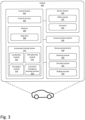
- a vehicle comprising an automated driving system, ADS, configured to execute an automatic collision avoidance steering maneuver, and a device for determining whether an automatic collision avoidance steering maneuver of the vehicle should be executed or not according to any embodiment of the third aspect.
- non-transitory is intended to describe a computer-readable storage medium (or “memory”) excluding propagating electromagnetic signals, but are not intended to otherwise limit the type of physical computer-readable storage device that is encompassed by the phrase computer-readable medium or memory.
- the terms “non-transitory computer readable medium” or “tangible memory” are intended to encompass types of storage devices that do not necessarily store information permanently, including for example, random access memory (RAM).
- Program instructions and data stored on a tangible computer-accessible storage medium in non-transitory form may further be transmitted by transmission media or signals such as electrical, electromagnetic, or digital signals, which may be conveyed via a communication medium such as a network and/or a wireless link.
- the term “non-transitory”, as used herein is a limitation of the medium itself (i.e., tangible, not a signal) as opposed to a limitation on data storage persistency (e.g., RAM vs. ROM).
- the present disclosure when the present disclosure is described in terms of a method, it may also be embodied in apparatus or device comprising one or more processors, one or more memories coupled to the one or more processors, where computer code is loaded to implement the method.
- the one or more memories may store one or more computer programs that perform the steps, services and functions disclosed herein when executed by the one or more processors in some embodiments.
- Fig. 1 may show a specific order of method steps, the order of the steps may differ from what is depicted.
- two or more steps may be performed concurrently or with partial concurrence.
- the steps of obtaining data (such as the predicted vehicle trajectory and the first and second thresholds as described below) may be interchanged based on a specific realization.
- Such variation will depend on the software and hardware systems chosen and on designer choice.
- software implementations could be accomplished with standard programming techniques with rule-based logic and other logic to accomplish the various steps.
- the above mentioned and described embodiments are only given as examples and should not be limiting to the present invention.
- Other solutions, uses, objectives, and functions within the scope of the invention as claimed in the below described patent claims should be apparent for the person skilled in the art.
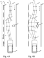
- the collision avoidance steering maneuver provides instructions on how the vehicle should drive in order to follow a collision avoidance path avoiding an obstacle.
- the collision avoidance path may be an in-lane collision avoidance path. I.e. a path avoiding an obstacle while remaining (at least substantially) within the current lane of the vehicle. Since the collision avoidance steering maneuver is closely related to the collision avoidance path, the proposed method 100 may be seen as a method for evaluating a collision avoidance path to determine if it could and/or should be followed or not.
- the (maximum) "attainable lateral acceleration” or (maximum) "attainable lateral jerk” is predefined and set so that a driver of the vehicle will be able to control the vehicle for any single fault in the ADS and vehicle platform.
- These limitations may thus be represented by the first and second threshold respectively which can be determined as a function of steering limitations implemented in the vehicle, e.g. as a "safety limiter”.
- the first and second threshold of lateral acceleration and lateral jerk respectively are further discussed in connection with Fig. 5 . It should be noted that additional steering capabilities than lateral acceleration and lateral jerk may also be used in determining whether the predicted vehicle trajectory is attainable or not, as is described in the following.
- the method 100 further comprises determining S108 whether the predicted vehicle trajectory is attainable or not by comparing the predicted lateral acceleration with the first threshold and the predicted lateral jerk with the second threshold. Put differently, it is determined whether the vehicle (or the maneuvering system of the vehicle) will be able to execute the collision avoidance steering maneuver in order to follow the collision avoidance path without exceeding the limitations set by the first and second threshold.
- the predicted vehicle trajectory being attainable may be interpreted as the vehicle will substantially follow the predicted vehicle trajectory if the collision avoidance steering maneuver is executed.
- the predicted vehicle trajectory not being attainable may be interpreted as the vehicle will (substantially) diverge from the predicted vehicle trajectory. It should be noted that the step of determining S108 whether the predicted vehicle trajectory is attainable or not can be seen as determining whether the collision avoidance steering maneuver (or collision avoidance path) is as attainable or not since the predicted vehicle trajectory is a result thereof.
- the predicted vehicle trajectory may be determined as attainable if the predicted lateral acceleration is smaller than or equal to the first threshold and the predicted lateral jerk is smaller than or equal to the second threshold. Consequently, the predicted vehicle trajectory may be determined as not attainable if the predicted lateral acceleration is greater than the first threshold or the predicted lateral jerk is greater than the second threshold.
- the predicted lateral acceleration which is compared to the first threshold may be the largest predicted lateral acceleration along the predicted vehicle trajectory.
- the predicted lateral jerk which is compared to the second threshold may be the largest predicted jerk along the predicted vehicle trajectory.
- the predicted lateral acceleration and lateral jerk which is compared to the first and second threshold respectively may be the absolute values of the predicted lateral acceleration and lateral jerk.
- the respective threshold may constitute an upper limit of the magnitude of attainable lateral acceleration and attainable lateral jerk.
- the first and second threshold may define a respective set of attainable lateral acceleration and attainable lateral jerk.
- the predicted lateral acceleration and lateral jerk which is compared to the first and second threshold respectively may be both positive and negative values.
- the predicted vehicle trajectory may comprise a set of values of predicted lateral acceleration and a set of values of predicted lateral jerk.
- the predicted vehicle trajectory may comprise a value of predicted lateral acceleration and a value of lateral jerk for each of a number of time instances along the vehicle trajectory.
- each position along the predicted vehicle trajectory may be associated with a corresponding value of predicted lateral acceleration and predicted lateral jerk.
- the predicted vehicle trajectory may be determined as attainable if each value of the set of values of predicted lateral acceleration is smaller than or equal to the first threshold and each value of the set of values of predicted lateral jerk is smaller than or equal to the second threshold. Consequently, the predicted vehicle trajectory may be determined as unattainable if at least one of the values of the set of values of predicted lateral acceleration is greater than the first threshold or at least one value of the set of values of predicted lateral jerk is greater than the second threshold.
- the step of obtaining S106 the first and second threshold may comprise obtaining S118 a set of values of attainable lateral accelerations and a set of values of attainable lateral jerks of the vehicle.
- Determining S108 whether the predicted vehicle trajectory is attainable or not may comprise determining S120 whether the predicted lateral acceleration and the predicted lateral jerk is within the set of values of attainable lateral accelerations and the set of values of attainable lateral jerk respectively.
- each value of the set of values of predicted lateral acceleration may be compared to the set of values of attainable lateral accelerations and each value of the set of values of predicted lateral jerk may be compared to the set of values of attainable lateral jerk.
- Having a set of values of attainable lateral accelerations and a set of values of attainable lateral jerk may allow for a more accurate determination of whether the predicted vehicle trajectory is attainable or not.
- the attainable lateral acceleration may be dependent on the attainable lateral jerk and vice versa.
- the attainable lateral acceleration and attainable lateral jerk may be dynamic in that they may depend on other factors. For example a velocity of the vehicle, or external factors such as road conditions (e.g. road surface, weather etc.) or driving conditions (e.g. visibility, traffic congestion etc.).
- road conditions e.g. road surface, weather etc.
- driving conditions e.g. visibility, traffic congestion etc.
- the first threshold may be an upper limit of a set of attainable lateral accelerations of the vehicle, such as the set of values of attainable lateral accelerations as described above.
- the second threshold may be an upper limit of a set of attainable lateral jerks of the vehicle, such as the set of values of attainable lateral jerks as described above. It goes without saying that since the lateral acceleration and lateral jerk may take both positive and negative values, either the actual value (i.e. keeping the sign) or the absolute values of the predicted lateral acceleration and the predicted lateral jerk may be compared to the first and second threshold depending on the implementation.
- the set of attainable lateral accelerations and the set of attainable lateral jerks may be dependent on a velocity of the vehicle.
- the method 100 may further comprise determining S104 a velocity of the vehicle along the predicted vehicle trajectory.
- the step of obtaining S106 the set of values of attainable lateral accelerations and the set of attainable lateral jerk of the vehicle may be based on the determined velocity of the vehicle. More specifically, the set of values of attainable lateral acceleration and the set of attainable lateral jerk which is obtained may be associated with the relevant velocity of the vehicle.
- the method 100 further comprises, in response to the predicted vehicle trajectory being attainable, communicating S110 to a control system of the vehicle, that the automatic collision avoidance steering maneuver shall be executed.
- a verification signal may be sent to the AES of the vehicle, or to a control system of the ADS (e.g. to a decision and control module of the ADS).
- the method 100 may be performed externally to the AES.
- the step of communicating S110 that the automatic collision avoidance steering maneuver shall be executed may be communicated to the AES.
- the method 100 may be performed as an integral part of the AES.
- said step of communicating S110 may be performed internally to a relevant submodule of the AES or to another system of the vehicle, such as a maneuvering system.
- the method 100 further comprises determining S112 a lateral offset of the vehicle along the predicted vehicle trajectory based on the predicted lateral acceleration and the predicted lateral jerk of the predicted vehicle trajectory and the first and second threshold.
- the lateral offset in a point k, O ( k ), can be determined according to the following, by considering how much the predicted lateral acceleration and predicted lateral jerk exceeds the first and second thresholds. Further, as seen in Fig. 5 , the lateral acceleration and lateral jerk can take both positive and negative values, depending on the direction.
- the first and second thresholds may comprise both a positive and a negative threshold respectively. More specifically, the first threshold of attainable lateral acceleration may be defined by a first positive threshold, a attainable_pos , and a first negative threshold, a attainable_neg .
- the second threshold of attainable lateral jerk may be defined by a second positive threshold, j attainable_pos , and a second negative threshold, i attainable_neg .
- the lateral offset O ( k ) can then be determined according to the following two-step algorithm, where v predicted is the predicted lateral velocity, (k-1) denotes the previous point, t sample is the sample time (i.e. time between two consecutive points), a predicted is the predicted lateral acceleration, j predicted is the predicted lateral jerk, a exceeding is the exceeding lateral acceleration, and j exceeding is the exceeding lateral jerk.
- the first step check if predicted lateral acceleration is attainable.
- the first step comprises the following.
- a attainable ( k - 1) can be either a attainable_pos ( k - 1) or a attainable_neg ( k - 1), depending on the situation.
- the predicted lateral velocity in a point k may be determined using the socalled Euler method (or forward Euler method) as understood from above. It should however be noted that other integration methods may be used as well as readily understood by the skilled person. Another example is the so called backward Euler method.
- the equations for determining the lateral offset may be further extended to take into account both total and relative to path quantities of the acceleration and jerk.
- the derivation of a predicted and j predicted may depend on how the steering collision avoidance path, and thus the predicted vehicle trajectory, is controlled.
- the controller e.g. a module of a control system 302 of the vehicle 300, tasked with determining control signals for controlling a steering of the vehicle
- the controller produces a curvature request with respect to the path to track
- this curvature can be directly translated into a lateral jerk request.
- the predicted lateral jerk, j predicted in the algorithm can be the resulting lateral jerk from a difference of the lateral jerk request from the controller and the lateral jerk from the predicted trajectory which the vehicle should follow.
- the method 100 can in short be summarised as follows. Firstly, the lateral offset is determined (e.g. by the algorithm above) for each point k along the predicted vehicle trajectory. Thus, the lateral offset may be calculated for all points along the predicted vehicle trajectory, i.e. also for points where the predicted lateral acceleration and predicted lateral jerk fulfils the first and second thresholds. However, in the points where the predicted lateral acceleration and lateral jerk are attainable, the lateral offset can be set to 0. Secondly, if the lateral offset O ( k ) for all points k are 0, then the predicted vehicle trajectory is determined as attainable. It can then be communicated to the control system of the vehicle that the collision avoidance steering maneuver shall be executed.
- the predicted vehicle trajectory can be determined as unattainable.
- the lateral offset in the points where it is different from zero can then be used to make a decision of whether to execute the collision avoidance steering maneuver or not based on further logic (as will be further described below).
- lateral offset should herein be interpreted as a measure of an expected offset of the vehicle from the collision avoidance path along a lateral direction.
- the lateral offset may arise from that the predicted vehicle trajectory is not attainable.
- the lateral offset may be based on the predicted lateral acceleration and the predicted lateral jerk of the predicted vehicle trajectory and the first and second threshold. For example, a larger offset can be expected the further the predicted lateral acceleration and the predicted lateral jerk exceeds the first and second thresholds (or the respective set of values) respectively. Similarly, a smaller lateral offset can be expected if the predicted lateral acceleration and lateral jerk only exceeds the respective threshold by a slight amount.
- the lateral offset may be seen as a path tracking error which results from the predicted lateral acceleration and predicted lateral jerk temporarily exceeding the attainable lateral acceleration and attainable lateral jerk.
- the method 100 further comprises, in response to the lateral offset being smaller than or equal to a third threshold, communicating S114, to the control system of the vehicle, that the automatic collision avoidance steering maneuver shall be executed.
- the third threshold may be selected such that the predicted vehicle trajectory with the lateral offset taken into consideration does not exceed a lane boundary or any other criterions such as security regulations.
- the third threshold may be defined such that the predicted vehicle trajectory with the lateral offset taken into consideration results in that no part of the vehicle is allowed to traverse the lane boundary defined by lane markers.
- the third threshold may be defined such that such that the predicted vehicle trajectory with the lateral offset taken into consideration results in that no part of the vehicle is allowed to traverse the lane marker by more than a defined length (i.e. a lane boundary offset from the lane marker by the defined length).
- the defined length may for example be a value in the range of 5 cm to 50 cm, and may further be defined based on a road type.
- the defined length may be longer for situations when the vehicle is traveling on a highway and the adjacent/neighboring lane is for vehicles traveling in the same direction as compared to situations when the vehicle is traveling on a road where the adjacent/neighboring lane is for vehicles traveling in the opposite direction.
- the defined length may be dynamically set/defined based on a road type upon which the vehicle is currently traveling.
- the ADS may be able to act in a wider range of scenarios resulting in a more secure and capable automated driving system, than the prior art.
- the step of communicating S114, S116 either that the automatic collision avoidance steering maneuver should be executed or not may be performed in response to a position of the predicted vehicle in the lateral direction, and taking into account the lateral offset, does not exceed/exceeds the third threshold respectively.
- the third threshold may then be represented by the lane boundary.
- the third threshold may have different values along the predicted vehicle trajectory depending on different factors.
- the third threshold may be based on a distance between the predicted vehicle trajectory and a lane boundary. For example, if the predicted vehicle trajectory is relatively close to the lane boundary (i.e. a relatively small distance between the predicted vehicle trajectory and the lane boundary), the third threshold may have a relatively low value. Thus, a stricter criterion on the automatic collision avoidance steering maneuver can be applied. If instead the predicted vehicle trajectory is relatively far from the lane boundary (i.e. a relatively large distance between the predicted vehicle trajectory and the lane boundary), the third threshold may have a relatively high value. Thus, a more lenient criterion can be applied on the automatic collision avoidance steering maneuver when there is a larger safety margin to the lane boundary.
- the step of communicating S114 to the control system of the vehicle, that the automatic collision avoidance steering maneuver shall be executed may be performed in response to each value of the set of lateral offsets being smaller than or equal to a corresponding threshold of the set of thirds thresholds. Consequently, the step of communicating S116 to the control system of the vehicle, that the automatic collision avoidance steering maneuver shall not be executed may be performed in response to at least one value of the set of lateral offsets being greater than its corresponding threshold of the set of third thresholds. In other words, it may be decided whether to execute the collision avoidance steering maneuver or not based on the comparison of the lateral offset with the corresponding value of the third threshold.
- Executable instructions for performing these functions are, optionally, included in a computer-accessible medium such as a non-transitory computer-readable storage medium or other computer program product configured for execution by one or more processors.
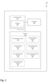
- Figure 2 is a schematic illustration of a device 200 for determining whether an automatic collision avoidance steering maneuver for a vehicle equipped with an automated driving system, ADS, should be executed or not.
- the device is configured to perform the techniques described in the foregoing with reference to Fig. 1 .
- the device 200 is provided locally in the vehicle.
- the device may be provided as an external device to the vehicle, such as a remote server.
- the device 200 may be an integrated device of the ADS of the vehicle.
- the device 200 may be an integrated device of an AES module of the ADS.
- the device 200 may be an external device to the ADS (or to the AES module) and communicatively connected to the ADS (or the AES module).
- Functions and operations of the device 200 may be implemented in the form of executable logic routines (e.g., lines of code, software programs, etc.) that are stored on a non-transitory computer readable recording medium (e.g., the memory 208) of the device 200 and are executed by the circuitry 202 (e.g. using the processor 204).
- the circuitry 202 is configured to execute a specific function
- the processor 204 of the circuitry 202 may be configured execute program code portions stored on the memory 208, wherein the stored program code portions correspond to the specific function.
- the functions and operations of the circuitry 202 may be a stand-alone software application or form a part of a software application that carries out additional tasks related to the circuitry 202.
- the described functions and operations may be considered a method that the corresponding device is configured to carry out, such as the method 100 discussed above in connection with Fig. 1 .
- the described functions and operations may be implemented in software, such functionality may as well be carried out via dedicated hardware or firmware, or some combination of one or more of hardware, firmware, and software.
- the following functions may be stored on the non-transitory computer readable recording medium.
- the control circuitry 202 is configured to (e.g. by execution of the first obtaining function 210) obtain a predicted vehicle trajectory for execution of the collision avoidance steering maneuver, wherein the predicted vehicle trajectory comprises a predicted lateral acceleration and a predicted lateral jerk of the vehicle along the predicted vehicle trajectory.
- the control circuitry 202 is further configured to (e.g. by execution of the second obtaining function 212) obtain a first threshold of attainable lateral acceleration and a second threshold of attainable lateral jerk of the vehicle.
- the control circuitry 202 is further configured to (e.g. by execution of the first determining function 214) determine whether the predicted vehicle trajectory is attainable or not by comparing the predicted lateral acceleration with the first threshold and the predicted lateral jerk with the second threshold.
- the control circuitry 202 is further configured to (e.g. by execution of the first communication function 218), in response to the predicted vehicle trajectory being attainable, communicate, to a control system of the vehicle, that the automatic collision avoidance steering maneuver shall be executed. More specifically, it may be communicated to the ADS (or the AES module) of the vehicle.
- the control circuitry 202 is further configured to (e.g. by execution of the second determining function 216), in response to the predicted vehicle trajectory not being attainable determine a lateral offset of the vehicle along the predicted vehicle trajectory based on the predicted lateral acceleration and the predicted lateral jerk of the predicted vehicle trajectory and the first and second threshold.
- the control circuitry 202 is further configured to (e.g. by execution of the second communication function 220), in response to the lateral offset being smaller than or equal to a third threshold, communicate, to the control system of the vehicle, that the automatic collision avoidance steering maneuver shall be executed.
- the control circuitry 202 is further configured to (e.g. by execution of the second communication function 220) in response to the lateral offset being greater than the third threshold, communicate to the control system of the vehicle, that the automatic collision avoidance steering maneuver shall not be executed.
- the predicted vehicle trajectory may be determined as attainable if the predicted lateral acceleration is smaller than or equal to the first threshold and the predicted lateral jerk is smaller than or equal to the second threshold.
- the predicted vehicle trajectory may be determined as not attainable if the predicted lateral acceleration is greater than the first threshold or the predicted lateral jerk is greater than the second threshold.
- the predicted vehicle trajectory may comprise a set of values of predicted lateral acceleration and a set of values of predicted lateral jerk.
- the predicted vehicle trajectory may be determined as attainable if each value of the set of values of predicted lateral acceleration is smaller than or equal to the first threshold and each value of the set of values of predicted lateral jerk is smaller than or equal to the second threshold.
- the predicted vehicle trajectory may be determined as unattainable if at least one of the values of the set of values of predicted lateral acceleration is greater than the first threshold or at least one value of the set of values of predicted lateral jerk is greater than the second threshold.
- the first and second threshold may comprise obtaining a set of values of attainable lateral accelerations and a set of values of attainable lateral jerk of the vehicle.
- Determining e.g. by the first determining function 214) whether the predicted vehicle trajectory is attainable or not may comprise determining whether the predicted lateral acceleration and the predicted lateral jerk is within the set of values of attainable lateral accelerations and the set of values of attainable lateral jerk respectively.
- a non-transitory computer-readable storage medium storing one or more programs configured to be executed by one or more processors of a vehicle control system, the one or more programs comprising instructions for performing the method 100 according to any one of the abovediscussed embodiments.
- a cloud computing system can be configured to perform any of the methods presented herein.
- the cloud computing system may comprise distributed cloud computing resources that jointly perform the methods presented herein under control of one or more computer program products.
Landscapes
- Engineering & Computer Science (AREA)
- Transportation (AREA)
- Mechanical Engineering (AREA)
- Automation & Control Theory (AREA)
- Chemical & Material Sciences (AREA)
- Combustion & Propulsion (AREA)
- Physics & Mathematics (AREA)
- Mathematical Physics (AREA)
- Control Of Driving Devices And Active Controlling Of Vehicle (AREA)
- Traffic Control Systems (AREA)
Claims (15)
- Procédé (100) mis en œuvre par ordinateur pour déterminer si une manœuvre de direction anticollision automatique pour un véhicule équipé d'un système de conduite automatisé, ADS, doit être exécutée ou non, le procédé (100) comprenant :l'obtention (S102) d'une trajectoire de véhicule prédite pour l'exécution de la manœuvre de direction anticollision, dans lequel la trajectoire de véhicule prédite comprend une accélération latérale prédite et une secousse latérale prédite du véhicule le long de la trajectoire de véhicule prédite ;l'obtention (S106) d'un premier seuil d'accélération latérale atteignable et d'un second seuil de secousse latérale atteignable du véhicule ; le procédé étant caractérisé parla détermination (S108) si la trajectoire prédite du véhicule est atteignable ou non en comparant l'accélération latérale prédite au premier seuil et la secousse latérale prédite au second seuil ;en réponse à la trajectoire prédite du véhicule qui est atteignable, la communication (S110), à un système de commande du véhicule, que la manœuvre de direction anticollision automatique doit être exécutée ;en réponse au fait que la trajectoire prévue du véhicule n'est pas atteignable :la détermination (S112) d'un décalage latéral du véhicule le long de la trajectoire prédite du véhicule sur la base de l'accélération latérale prédite et de la secousse latérale prédite de la trajectoire prédite du véhicule et du premier et du second seuil ;en réponse au décalage latéral étant inférieur ou égal à un troisième seuil, la communication (S114), au système de commande du véhicule, que la manœuvre de direction anticollision automatique doit être exécutée ;en réponse au décalage latéral étant supérieur au troisième seuil, la communication (S116) au système de commande du véhicule, que la manœuvre de direction anticollision automatique ne doit pas être exécutée.
- Procédé (100) selon la revendication 1, dans lequel la trajectoire prédite du véhicule est déterminée comme atteignable si l'accélération latérale prédite est inférieure ou égale au premier seuil et la secousse latérale prédite est inférieure ou égale au second seuil, et dans lequel la trajectoire prédite du véhicule est déterminée comme non atteignable si l'accélération latérale prédite est supérieure au premier seuil ou la secousse latérale prédite est supérieure au second seuil.
- Procédé (100) selon la revendication 1, dans lequel la trajectoire prédite du véhicule comprend un ensemble de valeurs d'accélération latérale prédite et un ensemble de valeurs de secousse latérale prédite,
dans lequel la trajectoire prédite du véhicule est déterminée comme atteignable si chaque valeur de l'ensemble de valeurs d'accélération latérale prédite est inférieure ou égale au premier seuil et chaque valeur de l'ensemble de valeurs de secousse latérale prédite est inférieure ou égale au second seuil, et la trajectoire prédite du véhicule est déterminée comme non atteignable si au moins une des valeurs de l'ensemble de valeurs d'accélération latérale prédite est supérieure au premier seuil ou au moins une valeur de l'ensemble de valeurs de secousse latérale prédite est supérieure au second seuil. - Procédé (100) selon l'une quelconque des revendications 1 à 3, dans lequel l'obtention (S106) des premier et second seuils comprend l'obtention (S118) d'un ensemble de valeurs d'accélérations latérales atteignables et d'un ensemble de valeurs de secousses latérales atteignables du véhicule,
dans lequel la détermination (S108) si la trajectoire de véhicule prédite est atteignable ou non comprend la détermination (S120) si l'accélération latérale prédite et la secousse latérale prédite sont respectivement dans l'ensemble de valeurs d'accélérations latérales atteignables et dans l'ensemble de valeurs de secousse latérale atteignable. - Procédé (100) selon la revendication 4, dans lequel le procédé (100) comprend en outre la détermination (S104) d'une vitesse du véhicule le long de la trajectoire de véhicule prédite, et
dans lequel l'obtention de l'ensemble de valeurs d'accélérations latérales atteignables et d'un ensemble de valeurs de secousse latérale atteignable du véhicule est basée sur la vitesse déterminée du véhicule. - Procédé (100) selon l'une quelconque des revendications 1 à 5, dans lequel la détermination (S112) du décalage latéral comprend la détermination (S122) d'un ensemble de valeurs de décalage latéral, chaque valeur de l'ensemble de décalages latéraux étant associée à un point différent le long de la trajectoire prédite du véhicule,le troisième seuil comprenant un ensemble de troisièmes seuils, chaque seuil de l'ensemble de troisièmes seuils correspondant à un point des différents points le long de la trajectoire prédite du véhicule,la communication (S114) au système de commande du véhicule de l'obligation d'exécuter la manœuvre de direction anticollision automatique étant effectuée en réponse à chaque valeur de l'ensemble de décalages latéraux inférieure étant égale à un seuil correspondant de l'ensemble de troisièmes seuils, etla communication (S116) au système de commande du véhicule de l'obligation d'exécuter la manœuvre de direction anticollision automatique étant effectuée en réponse à au moins une valeur de l'ensemble de décalages latéraux étant supérieure à son seuil correspondant de l'ensemble de troisièmes seuils.
- Procédé selon la revendication 1 à 6, dans lequel le troisième seuil est basé sur une distance entre la trajectoire prédite du véhicule et une limite de voie.
- Support de stockage non transitoire lisible par ordinateur stockant un ou plusieurs programmes configurés pour être exécutés par un ou plusieurs processeurs d'un système de traitement, les un ou plusieurs programmes comprenant des instructions pour réaliser le procédé selon l'une quelconque des revendications 1 à 7.
- Dispositif (200) permettant de déterminer si une manœuvre de direction anticollision automatique pour un véhicule équipé d'un système de conduite automatisé, ADS, doit être exécutée ou non, le dispositif (200) comprenant un circuit de commande (202) configuré pour :obtenir une trajectoire de véhicule prédite pour l'exécution de la manœuvre de direction anticollision, dans lequel la trajectoire de véhicule prédite comprend une accélération latérale prédite et une secousse latérale prédite du véhicule le long de la trajectoire de véhicule prédite ;obtenir un premier seuil d'accélération latérale atteignable et un second seuil de secousse latérale atteignable du véhicule ; le dispositif étant caractérisé en ce qu'il est configuré pourdéterminer si la trajectoire prédite du véhicule est atteignable ou non en comparant l'accélération latérale prédite au premier seuil et la secousse latérale prédite au second seuil ;en réponse à la trajectoire prévue du véhicule étant atteignable, communiquer, à un système de commande du véhicule, que la manœuvre de direction anticollision automatique doit être exécutée ;en réponse au fait que la trajectoire prévue du véhicule n'est pas atteignable :déterminer un décalage latéral du véhicule le long de la trajectoire prévue du véhicule en fonction de l'accélération latérale prévue et de la secousse latérale prévue de la trajectoire prévue du véhicule et du premier et du second seuil ;en réponse au décalage latéral étant inférieur ou égal à un troisième seuil, communiquer au système de commande du véhicule que la manœuvre de direction anticollision automatique doit être exécutée ;en réponse au décalage latéral étant supérieur au troisième seuil, communiquer au système de commande du véhicule que la manœuvre de direction anticollision ne doit pas être exécutée.
- Dispositif (200) selon la revendication 9, dans lequel la trajectoire prédite du véhicule est déterminée comme atteignable si l'accélération latérale prédite est inférieure ou égale au premier seuil et la secousse latérale prédite est inférieure ou égale au second seuil, et dans lequel la trajectoire prédite du véhicule est déterminée comme non atteignable si l'accélération latérale prédite est supérieure au premier seuil ou la secousse latérale prédite est supérieure au second seuil.
- Dispositif (200) selon la revendication 9, dans lequel la trajectoire prédite du véhicule comprend un ensemble de valeurs d'accélération latérale prédite et un ensemble de valeurs de secousse latérale prédite,
la trajectoire prédite du véhicule est déterminée comme atteignable si chaque valeur de l'ensemble de valeurs d'accélération latérale prédite est inférieure ou égale au premier seuil et chaque valeur de l'ensemble de valeurs de secousse latérale prédite est inférieure ou égale au second seuil, dans lequel la trajectoire prédite du véhicule est déterminée comme non atteignable si au moins une des valeurs de l'ensemble de valeurs d'accélération latérale prédite est supérieure au premier seuil ou au moins une valeur de l'ensemble de valeurs de secousse latérale prédite est supérieure au second seuil. - Dispositif (200) selon l'une quelconque des revendications 9 à 12, dans lequel l'obtention du premier et du second seuil comprend l'obtention d'un ensemble de valeurs d'accélérations latérales atteignables et d'un ensemble de valeurs de secousse latérale atteignable du véhicule,
dans lequel la détermination si la trajectoire prédite du véhicule est atteignable ou non comprend la détermination si l'accélération latérale prédite et la secousse latérale prédite se situent respectivement dans l'ensemble de valeurs d'accélérations latérale atteignable et l'ensemble de valeurs de secousse latérale atteignable. - Dispositif (200) selon la revendication 12, dans lequel le circuit de commande (202) est en outre configuré pour déterminer une vitesse du véhicule le long de la trajectoire de véhicule prédite, et
dans lequel l'obtention de l'ensemble de valeurs d'accélérations latérales atteignables et d'un ensemble de valeurs de secousse latérale atteignable du véhicule est basée sur la vitesse déterminée du véhicule. - Dispositif (200) selon l'une quelconque des revendications 9 à 13, dans lequel le circuit de commande (202) est en outre configuré pour déterminer un ensemble de valeurs de décalage latéral, chaque valeur de l'ensemble de décalages latéraux étant associée à un point différent le long de la trajectoire prédite du véhicule,dans lequel le troisième seuil comprend un ensemble de troisièmes seuils, chaque seuil de l'ensemble de troisièmes seuils correspondant à une position des différentes positions le long de la trajectoire prédite du véhicule,dans lequel le circuit de commande (200) est en outre configuré pour communiquer, au système de commande du véhicule, que la manœuvre de direction anticollision automatique doit être exécutée, en réponse à chaque valeur de l'ensemble de décalages latéraux étant inférieure ou égale à un seuil correspondant de l'ensemble de troisièmes seuils, etcommuniquer, au système de commande du véhicule, que la manœuvre de direction anticollision automatique ne doit pas être exécutée, en réponse à au moins une valeur de l'ensemble de décalages latéraux supérieure à son seuil correspondant de l'ensemble de troisièmes seuils.
- Véhicule (300) comprenant :un système de conduite automatisé, ADS, (310) configuré pour exécuter une manœuvre de direction anticollision automatique ; etun dispositif (200) permettant de déterminer si une manœuvre de direction anticollision automatique du véhicule (300) doit être réalisé ou non, selon l'une quelconque des revendications 9 à 14.
Priority Applications (3)
| Application Number | Priority Date | Filing Date | Title |
|---|---|---|---|
| EP22201807.9A EP4357213B1 (fr) | 2022-10-17 | 2022-10-17 | Procédé pour déterminer si une manoeuvre de direction d'évitement de collision automatique doit être exécutée ou non |
| US18/476,407 US12434767B2 (en) | 2022-10-17 | 2023-09-28 | Method for determining whether an automatic collision avoidance steering maneuver should be executed or not |
| CN202311344510.6A CN117901851A (zh) | 2022-10-17 | 2023-10-17 | 用于确定自动碰撞避免转向操纵是否应被执行的方法 |
Applications Claiming Priority (1)
| Application Number | Priority Date | Filing Date | Title |
|---|---|---|---|
| EP22201807.9A EP4357213B1 (fr) | 2022-10-17 | 2022-10-17 | Procédé pour déterminer si une manoeuvre de direction d'évitement de collision automatique doit être exécutée ou non |
Publications (2)
| Publication Number | Publication Date |
|---|---|
| EP4357213A1 EP4357213A1 (fr) | 2024-04-24 |
| EP4357213B1 true EP4357213B1 (fr) | 2025-07-09 |
Family
ID=83898127
Family Applications (1)
| Application Number | Title | Priority Date | Filing Date |
|---|---|---|---|
| EP22201807.9A Active EP4357213B1 (fr) | 2022-10-17 | 2022-10-17 | Procédé pour déterminer si une manoeuvre de direction d'évitement de collision automatique doit être exécutée ou non |
Country Status (3)
| Country | Link |
|---|---|
| US (1) | US12434767B2 (fr) |
| EP (1) | EP4357213B1 (fr) |
| CN (1) | CN117901851A (fr) |
Families Citing this family (3)
| Publication number | Priority date | Publication date | Assignee | Title |
|---|---|---|---|---|
| US20240326791A1 (en) * | 2023-03-30 | 2024-10-03 | Zoox, Inc. | Collision avoidance with trajectory evaluation |
| US20250002047A1 (en) * | 2023-06-30 | 2025-01-02 | Zoox, Inc. | Trajectory selection in response to triggering events |
| US12424104B2 (en) | 2023-10-16 | 2025-09-23 | Plusai, Inc. | Motion planning for autonomous vehicle driving using vehicle-to-infrastructure communication |
Family Cites Families (14)
| Publication number | Priority date | Publication date | Assignee | Title |
|---|---|---|---|---|
| EP1926654B1 (fr) * | 2005-09-15 | 2009-12-09 | Continental Teves AG & Co. oHG | Procede et dispositif pour conduire un vehicule |
| US9318023B2 (en) * | 2011-08-31 | 2016-04-19 | GM Global Technology Operations LLC | System and method for collision avoidance maneuver path determination with jerk limit |
| US8849515B2 (en) * | 2012-07-24 | 2014-09-30 | GM Global Technology Operations LLC | Steering assist in driver initiated collision avoidance maneuver |
| EP2759897B1 (fr) | 2013-01-24 | 2019-04-24 | Volvo Car Corporation | Procédé et agencement pour déterminer une trajectoire |
| US9278713B2 (en) | 2013-12-11 | 2016-03-08 | GM Global Technology Operations LLC | Collision avoidance control integrated with EPS controller |
| JP7253908B2 (ja) * | 2018-12-03 | 2023-04-07 | 日立Astemo株式会社 | 車両制御装置 |
| US11390300B2 (en) * | 2019-10-18 | 2022-07-19 | Uatc, Llc | Method for using lateral motion to optimize trajectories for autonomous vehicles |
| JP7408695B2 (ja) * | 2020-01-30 | 2024-01-05 | 日立Astemo株式会社 | 車両制御装置、車両制御方法、及び車両制御システム |
| US12097844B2 (en) * | 2020-04-30 | 2024-09-24 | Zoox, Inc. | Constraining vehicle operation based on uncertainty in perception and/or prediction |
| EP3971526B1 (fr) * | 2020-09-18 | 2024-05-08 | Zenuity AB | Planification de trajet dans des environnements de conduite autonome |
| US11608089B2 (en) * | 2020-11-09 | 2023-03-21 | GM Global Technology Operations LLC | Method and apparatus for automated lateral controls adaptation in response to rapid trajectory changes |
| US11827240B2 (en) * | 2020-12-09 | 2023-11-28 | Uatc, Llc | Systems and methods for costing autonomous vehicle maneuvers |
| US12084048B2 (en) * | 2021-02-16 | 2024-09-10 | Atieva, Inc. | Physical feedback confirmation from assisted- driving system about traffic event |
| JP7637253B2 (ja) * | 2021-09-09 | 2025-02-27 | 日立Astemo株式会社 | 車両制御装置、車両制御方法、及び車両制御システム |
-
2022
- 2022-10-17 EP EP22201807.9A patent/EP4357213B1/fr active Active
-
2023
- 2023-09-28 US US18/476,407 patent/US12434767B2/en active Active
- 2023-10-17 CN CN202311344510.6A patent/CN117901851A/zh active Pending
Also Published As
| Publication number | Publication date |
|---|---|
| EP4357213A1 (fr) | 2024-04-24 |
| CN117901851A (zh) | 2024-04-19 |
| US20240124060A1 (en) | 2024-04-18 |
| US12434767B2 (en) | 2025-10-07 |
Similar Documents
| Publication | Publication Date | Title |
|---|---|---|
| US11597385B2 (en) | Autonomous vehicle and vehicle running control method using the same | |
| US11532097B2 (en) | Method for estimating the quality of localization in the self-localization of a vehicle, device for carrying out the steps of the method, vehicle, and computer program | |
| EP4357213B1 (fr) | Procédé pour déterminer si une manoeuvre de direction d'évitement de collision automatique doit être exécutée ou non | |
| CN110949376B (zh) | 车辆控制装置、车辆控制方法及存储介质 | |
| US20180056998A1 (en) | System and Method for Multi-Vehicle Path Planning Technical Field | |
| EP3525192B1 (fr) | Procédé d'évaluation de véhicule, procédé de correction d'itinéraire de déplacement, dispositif d'évaluation de véhicule et dispositif de correction d'itinéraire de déplacement | |
| CN112262066B (zh) | 行驶辅助方法以及行驶辅助装置 | |
| JP2019159428A (ja) | 車両制御装置、車両制御方法及びプログラム | |
| US20210009126A1 (en) | Vehicle control device, vehicle control method, and storage medium | |
| US20190299987A1 (en) | Vehicle control device, vehicle control method, and storage medium | |
| US20190384319A1 (en) | Moving body assistance system and moving body assistance method | |
| EP3626570B1 (fr) | Procédé et dispositif d'aide à la conduite | |
| JP2019214291A (ja) | 走行支援方法及び走行支援装置 | |
| CN113200043B (zh) | 自动地控制车道改变辅助的方法和控制单元 | |
| US20190299985A1 (en) | Vehicle control device, vehicle control method, and storage medium | |
| US20250002056A1 (en) | Dynamic risk adaptation in a vehicle | |
| EP4389551B1 (fr) | Procédé mis en oeuvre par ordinateur pour gérer une expansion de domaine de conception opérationnelle pour un système de conduite automatisée | |
| EP4620768A1 (fr) | Interventions de direction pour véhicules | |
| EP4559771A1 (fr) | Procédé et système de planification de mesures pour un véhicule | |
| EP4675307A1 (fr) | Procédé d'extension d'espace libre pour conduite autonome | |
| EP4431355A1 (fr) | Système de commande de frein de véhicule et procédé associé | |
| WO2026000351A1 (fr) | Procédé de fonctionnement d'un système de conduite automatisée (ads) d'un véhicule et appareil associé |
Legal Events
| Date | Code | Title | Description |
|---|---|---|---|
| PUAI | Public reference made under article 153(3) epc to a published international application that has entered the european phase |
Free format text: ORIGINAL CODE: 0009012 |
|
| STAA | Information on the status of an ep patent application or granted ep patent |
Free format text: STATUS: THE APPLICATION HAS BEEN PUBLISHED |
|
| AK | Designated contracting states |
Kind code of ref document: A1 Designated state(s): AL AT BE BG CH CY CZ DE DK EE ES FI FR GB GR HR HU IE IS IT LI LT LU LV MC ME MK MT NL NO PL PT RO RS SE SI SK SM TR |
|
| STAA | Information on the status of an ep patent application or granted ep patent |
Free format text: STATUS: REQUEST FOR EXAMINATION WAS MADE |
|
| 17P | Request for examination filed |
Effective date: 20241007 |
|
| RBV | Designated contracting states (corrected) |
Designated state(s): AL AT BE BG CH CY CZ DE DK EE ES FI FR GB GR HR HU IE IS IT LI LT LU LV MC ME MK MT NL NO PL PT RO RS SE SI SK SM TR |
|
| GRAP | Despatch of communication of intention to grant a patent |
Free format text: ORIGINAL CODE: EPIDOSNIGR1 |
|
| STAA | Information on the status of an ep patent application or granted ep patent |
Free format text: STATUS: GRANT OF PATENT IS INTENDED |
|
| INTG | Intention to grant announced |
Effective date: 20250304 |
|
| GRAS | Grant fee paid |
Free format text: ORIGINAL CODE: EPIDOSNIGR3 |
|
| GRAA | (expected) grant |
Free format text: ORIGINAL CODE: 0009210 |
|
| STAA | Information on the status of an ep patent application or granted ep patent |
Free format text: STATUS: THE PATENT HAS BEEN GRANTED |
|
| P01 | Opt-out of the competence of the unified patent court (upc) registered |
Free format text: CASE NUMBER: APP_22754/2025 Effective date: 20250514 |
|
| AK | Designated contracting states |
Kind code of ref document: B1 Designated state(s): AL AT BE BG CH CY CZ DE DK EE ES FI FR GB GR HR HU IE IS IT LI LT LU LV MC ME MK MT NL NO PL PT RO RS SE SI SK SM TR |
|
| REG | Reference to a national code |
Ref country code: GB Ref legal event code: FG4D |
|
| REG | Reference to a national code |
Ref country code: CH Ref legal event code: EP |
|
| REG | Reference to a national code |
Ref country code: IE Ref legal event code: FG4D |
|
| REG | Reference to a national code |
Ref country code: DE Ref legal event code: R096 Ref document number: 602022017244 Country of ref document: DE |
|
| PGFP | Annual fee paid to national office [announced via postgrant information from national office to epo] |
Ref country code: SE Payment date: 20250922 Year of fee payment: 4 |
|
| REG | Reference to a national code |
Ref country code: SE Ref legal event code: TRGR |
|
| REG | Reference to a national code |
Ref country code: NL Ref legal event code: MP Effective date: 20250709 |
|
| PG25 | Lapsed in a contracting state [announced via postgrant information from national office to epo] |
Ref country code: PT Free format text: LAPSE BECAUSE OF FAILURE TO SUBMIT A TRANSLATION OF THE DESCRIPTION OR TO PAY THE FEE WITHIN THE PRESCRIBED TIME-LIMIT Effective date: 20251110 |
|
| PG25 | Lapsed in a contracting state [announced via postgrant information from national office to epo] |
Ref country code: NL Free format text: LAPSE BECAUSE OF FAILURE TO SUBMIT A TRANSLATION OF THE DESCRIPTION OR TO PAY THE FEE WITHIN THE PRESCRIBED TIME-LIMIT Effective date: 20250709 |
|
| REG | Reference to a national code |
Ref country code: AT Ref legal event code: MK05 Ref document number: 1811611 Country of ref document: AT Kind code of ref document: T Effective date: 20250709 |
|
| PG25 | Lapsed in a contracting state [announced via postgrant information from national office to epo] |
Ref country code: IS Free format text: LAPSE BECAUSE OF FAILURE TO SUBMIT A TRANSLATION OF THE DESCRIPTION OR TO PAY THE FEE WITHIN THE PRESCRIBED TIME-LIMIT Effective date: 20251109 |
|
| PGFP | Annual fee paid to national office [announced via postgrant information from national office to epo] |
Ref country code: DE Payment date: 20250919 Year of fee payment: 4 |
|
| PG25 | Lapsed in a contracting state [announced via postgrant information from national office to epo] |
Ref country code: NO Free format text: LAPSE BECAUSE OF FAILURE TO SUBMIT A TRANSLATION OF THE DESCRIPTION OR TO PAY THE FEE WITHIN THE PRESCRIBED TIME-LIMIT Effective date: 20251009 |
|
| REG | Reference to a national code |
Ref country code: LT Ref legal event code: MG9D |
|
| PG25 | Lapsed in a contracting state [announced via postgrant information from national office to epo] |
Ref country code: AT Free format text: LAPSE BECAUSE OF FAILURE TO SUBMIT A TRANSLATION OF THE DESCRIPTION OR TO PAY THE FEE WITHIN THE PRESCRIBED TIME-LIMIT Effective date: 20250709 |
|
| PG25 | Lapsed in a contracting state [announced via postgrant information from national office to epo] |
Ref country code: FI Free format text: LAPSE BECAUSE OF FAILURE TO SUBMIT A TRANSLATION OF THE DESCRIPTION OR TO PAY THE FEE WITHIN THE PRESCRIBED TIME-LIMIT Effective date: 20250709 |
|
| PG25 | Lapsed in a contracting state [announced via postgrant information from national office to epo] |
Ref country code: HR Free format text: LAPSE BECAUSE OF FAILURE TO SUBMIT A TRANSLATION OF THE DESCRIPTION OR TO PAY THE FEE WITHIN THE PRESCRIBED TIME-LIMIT Effective date: 20250709 |
|
| PG25 | Lapsed in a contracting state [announced via postgrant information from national office to epo] |
Ref country code: GR Free format text: LAPSE BECAUSE OF FAILURE TO SUBMIT A TRANSLATION OF THE DESCRIPTION OR TO PAY THE FEE WITHIN THE PRESCRIBED TIME-LIMIT Effective date: 20251010 |
|
| PG25 | Lapsed in a contracting state [announced via postgrant information from national office to epo] |
Ref country code: LV Free format text: LAPSE BECAUSE OF FAILURE TO SUBMIT A TRANSLATION OF THE DESCRIPTION OR TO PAY THE FEE WITHIN THE PRESCRIBED TIME-LIMIT Effective date: 20250709 |
|
| PG25 | Lapsed in a contracting state [announced via postgrant information from national office to epo] |
Ref country code: PL Free format text: LAPSE BECAUSE OF FAILURE TO SUBMIT A TRANSLATION OF THE DESCRIPTION OR TO PAY THE FEE WITHIN THE PRESCRIBED TIME-LIMIT Effective date: 20250709 Ref country code: BG Free format text: LAPSE BECAUSE OF FAILURE TO SUBMIT A TRANSLATION OF THE DESCRIPTION OR TO PAY THE FEE WITHIN THE PRESCRIBED TIME-LIMIT Effective date: 20250709 |
|
| PG25 | Lapsed in a contracting state [announced via postgrant information from national office to epo] |
Ref country code: RS Free format text: LAPSE BECAUSE OF FAILURE TO SUBMIT A TRANSLATION OF THE DESCRIPTION OR TO PAY THE FEE WITHIN THE PRESCRIBED TIME-LIMIT Effective date: 20251009 |
|
| PG25 | Lapsed in a contracting state [announced via postgrant information from national office to epo] |
Ref country code: ES Free format text: LAPSE BECAUSE OF FAILURE TO SUBMIT A TRANSLATION OF THE DESCRIPTION OR TO PAY THE FEE WITHIN THE PRESCRIBED TIME-LIMIT Effective date: 20250709 |
|
| PG25 | Lapsed in a contracting state [announced via postgrant information from national office to epo] |
Ref country code: RO Free format text: LAPSE BECAUSE OF FAILURE TO SUBMIT A TRANSLATION OF THE DESCRIPTION OR TO PAY THE FEE WITHIN THE PRESCRIBED TIME-LIMIT Effective date: 20250709 |
|
| PG25 | Lapsed in a contracting state [announced via postgrant information from national office to epo] |
Ref country code: SM Free format text: LAPSE BECAUSE OF FAILURE TO SUBMIT A TRANSLATION OF THE DESCRIPTION OR TO PAY THE FEE WITHIN THE PRESCRIBED TIME-LIMIT Effective date: 20250709 |
|
| PG25 | Lapsed in a contracting state [announced via postgrant information from national office to epo] |
Ref country code: DK Free format text: LAPSE BECAUSE OF FAILURE TO SUBMIT A TRANSLATION OF THE DESCRIPTION OR TO PAY THE FEE WITHIN THE PRESCRIBED TIME-LIMIT Effective date: 20250709 |
|
| PG25 | Lapsed in a contracting state [announced via postgrant information from national office to epo] |
Ref country code: IT Free format text: LAPSE BECAUSE OF FAILURE TO SUBMIT A TRANSLATION OF THE DESCRIPTION OR TO PAY THE FEE WITHIN THE PRESCRIBED TIME-LIMIT Effective date: 20250709 |
|
| PG25 | Lapsed in a contracting state [announced via postgrant information from national office to epo] |
Ref country code: CZ Free format text: LAPSE BECAUSE OF FAILURE TO SUBMIT A TRANSLATION OF THE DESCRIPTION OR TO PAY THE FEE WITHIN THE PRESCRIBED TIME-LIMIT Effective date: 20250709 |
|
| PG25 | Lapsed in a contracting state [announced via postgrant information from national office to epo] |
Ref country code: EE Free format text: LAPSE BECAUSE OF FAILURE TO SUBMIT A TRANSLATION OF THE DESCRIPTION OR TO PAY THE FEE WITHIN THE PRESCRIBED TIME-LIMIT Effective date: 20250709 Ref country code: SK Free format text: LAPSE BECAUSE OF FAILURE TO SUBMIT A TRANSLATION OF THE DESCRIPTION OR TO PAY THE FEE WITHIN THE PRESCRIBED TIME-LIMIT Effective date: 20250709 |