EP4357559B1 - Verriegelungssystem für eine beckenabdeckung - Google Patents
Verriegelungssystem für eine beckenabdeckung Download PDFInfo
- Publication number
- EP4357559B1 EP4357559B1 EP23203144.3A EP23203144A EP4357559B1 EP 4357559 B1 EP4357559 B1 EP 4357559B1 EP 23203144 A EP23203144 A EP 23203144A EP 4357559 B1 EP4357559 B1 EP 4357559B1
- Authority
- EP
- European Patent Office
- Prior art keywords
- locking
- retaining element
- configuration
- locking elements
- pool
- Prior art date
- Legal status (The legal status is an assumption and is not a legal conclusion. Google has not performed a legal analysis and makes no representation as to the accuracy of the status listed.)
- Active
Links
Images


Classifications
-
- E—FIXED CONSTRUCTIONS
- E04—BUILDING
- E04H—BUILDINGS OR LIKE STRUCTURES FOR PARTICULAR PURPOSES; SWIMMING OR SPLASH BATHS OR POOLS; MASTS; FENCING; TENTS OR CANOPIES, IN GENERAL
- E04H4/00—Swimming or splash baths or pools
- E04H4/06—Safety devices; Coverings for baths
- E04H4/08—Coverings consisting of rigid elements, e.g. coverings composed of separate or connected elements
- E04H4/082—Coverings consisting of rigid elements, e.g. coverings composed of separate or connected elements composed of flexibly or hingedly-connected slat-like elements, which may or may not be wound-up on a fixed axis
-
- E—FIXED CONSTRUCTIONS
- E05—LOCKS; KEYS; WINDOW OR DOOR FITTINGS; SAFES
- E05B—LOCKS; ACCESSORIES THEREFOR; HANDCUFFS
- E05B47/00—Operating or controlling locks or other fastening devices by electric or magnetic means
- E05B47/0046—Electric or magnetic means in the striker or on the frame; Operating or controlling the striker plate
-
- E—FIXED CONSTRUCTIONS
- E05—LOCKS; KEYS; WINDOW OR DOOR FITTINGS; SAFES
- E05B—LOCKS; ACCESSORIES THEREFOR; HANDCUFFS
- E05B15/00—Other details of locks; Parts for engagement by bolts of fastening devices
- E05B15/10—Bolts of locks or night latches
- E05B15/108—Bolts with multiple head
-
- E—FIXED CONSTRUCTIONS
- E05—LOCKS; KEYS; WINDOW OR DOOR FITTINGS; SAFES
- E05B—LOCKS; ACCESSORIES THEREFOR; HANDCUFFS
- E05B47/00—Operating or controlling locks or other fastening devices by electric or magnetic means
- E05B47/0001—Operating or controlling locks or other fastening devices by electric or magnetic means with electric actuators; Constructional features thereof
- E05B2047/0014—Constructional features of actuators or power transmissions therefor
- E05B2047/0018—Details of actuator transmissions
- E05B2047/0023—Nuts or nut-like elements moving along a driven threaded axle
-
- E—FIXED CONSTRUCTIONS
- E05—LOCKS; KEYS; WINDOW OR DOOR FITTINGS; SAFES
- E05B—LOCKS; ACCESSORIES THEREFOR; HANDCUFFS
- E05B47/00—Operating or controlling locks or other fastening devices by electric or magnetic means
- E05B47/0001—Operating or controlling locks or other fastening devices by electric or magnetic means with electric actuators; Constructional features thereof
- E05B47/0012—Operating or controlling locks or other fastening devices by electric or magnetic means with electric actuators; Constructional features thereof with rotary electromotors
Definitions
- the present invention relates to the field of pool covers such as swimming pools, and more particularly relates to a system for locking a pool cover, and a pool covering system comprising such a locking system.
- Pond covers are used primarily to protect the pond from water pollution and heat loss, but also to ensure the safety of children near the pond.
- a system for covering a pool comprises a pool cover formed from a plurality of floating blades articulated along parallel axes, and a winding device connected to the pool cover and configured to wind and unwind the pool cover between a deployed position in which the pool cover covers all or substantially all of the pool and a retracted position in which the pool cover provides access to the pool.
- the document EP2682540 describes a locking system configured to automatically lock a pool cover in its deployed position.
- a locking system comprises an automatic locking device intended to be fixed to a wall of the pool, and for example to a wall of the pool opposite the winding device, and a retaining part intended to be fixed to the pool cover, and for example to the end of the pool cover opposite the winding device, and provided with a retaining housing.
- the automatic locking device comprises a locking finger movable vertically between a locking position in which the locking finger is inserted into the retaining housing and locks the pool cover in its deployed position, and an unlocking position in which the locking finger allows movement of the pool cover towards its release position.
- Such a configuration of the locking device is likely to induce, in the event of a heavy fall of a person onto the pool cover, proximity of the locking device, a breakage of the locking finger and thus the formation of a gap, between the pool cover and an edge of the pool, into which the said person could fall.
- Other locking systems for pool covers are disclosed in the documents EP3196384A And EP3763899A .
- the present invention aims to remedy these drawbacks.
- the technical problem underlying the invention therefore consists of providing a system for locking a pool cover which is of simple structure, while ensuring secure and reliable locking of a pool cover.
- Such a configuration of the locking device, and more particularly of the first and second locking elements, ensures secure and reliable locking of the retaining element, and therefore of the pool cover in the deployed configuration.
- the locking system may further have one or more of the following features, taken alone or in combination.
- the locking device is configured such that under conditions of use, the sliding direction extends substantially horizontally.
- the locking device is configured such that under conditions of use, the sliding direction extends substantially perpendicular to a direction of movement of the pool cover.
- the retaining element is configured to be inserted through the passage opening in an insertion direction which is substantially parallel to the direction of movement of the pool cover, and therefore which is substantially horizontal.
- the retaining element is configured to be inserted into the internal chamber, via the passage opening, in an insertion direction which is substantially vertical.
- the first and second locking elements are configured to extend at least partially opposite the passage opening when the first and second locking elements occupy the locking configuration.
- the locking system comprises a guide device configured to slidably guide the first and second locking elements in the sliding direction when the first and second locking elements are moved by the drive mechanism between the release configuration and the locking configuration.
- the guide device comprises two guide rods which are fixed to the fixing housing and which extend substantially parallel to the sliding direction, the first and second locking elements being slidably mounted on the two guide rods.
- each of the guide rods has a circular section.
- the first locking element comprises two first upper guide portions offset from each other in the sliding direction and each provided with a first upper guide orifice, and two first lower guide portions offset from each other in the sliding direction and each provided with a first lower guide orifice
- the second locking element comprises two second upper guide portions offset from each other in the sliding direction and each provided with a second upper guide orifice, and two second lower guide portions offset from each other in the sliding direction and each provided with a second lower guide hole, one of the guide rods extending through the first and second upper guide holes and the other of the guide rods extending through the first and second lower guide holes.
- the first and second endless screws respectively have first and second screw pitches which are substantially identical.
- the first and second worm screws respectively have first and second threads which extend in first and second thread orientations which are opposite to each other.
- the rotational drive device is configured to rotate the first worm screw and the second worm screw in a first direction of rotation when the first and second locking elements are moved from the locking configuration to the release configuration and to rotate the first worm screw and the second worm screw in a second direction of rotation, which is opposite to the first direction of rotation, when the first and second locking elements are moved from the release configuration to the locking configuration.
- the first and second worm screws extend substantially coaxially with respect to each other.
- the first and second worm screws are made in a single piece.
- the drive mechanism comprises a drive rod comprising the first and second worm screws.
- the rotation drive device comprises a drive motor housed in the fixing housing and configured to drive the first and second worm screws in rotation respectively around the first and second central longitudinal axes.
- the drive motor comprises an output shaft which is rotatably coupled to the first and second worm screws.
- the output shaft of the drive motor is substantially coaxial with the first and second worm screws.
- the locking system comprises a control unit configured to control the operation of the drive mechanism.
- control unit is housed in the fixing housing.
- the locking system further comprises a detection system configured to detect when the retaining element is received in the internal chamber, the control unit being configured to automatically control a movement of the first and second locking elements into the locking configuration when the detection system has detected that the retaining element is received in the internal chamber.
- the detection system is a contactless detection system.
- the detection system comprises a presence detector which is attached to the attachment housing and which is configured to detect when the retaining element is received in the internal chamber.
- the detection system is configured to send a measurement signal to the control unit, the control unit being configured to compare the measurement signal to a predetermined threshold value and to control a movement of the first and second locking elements into the locking configuration when the measurement signal is greater than or equal to the predetermined threshold value.
- the detection system comprises at least one permanent magnet attached to the retaining element, and a presence detector attached to the fixing housing and configured to measure a magnetic field, the presence detector being configured to detect the reception of the retaining element. retained in the internal chamber when a magnetic field measured by the presence detector is greater than a predetermined threshold.
- the presence detector is a Hall effect sensor.
- the presence detector is located at least partly opposite the passage opening.
- the locking system comprises a communication module, such as a radio communication module, fixed to the fixing housing and comprising a receiver configured to receive an unlocking control signal transmitted by a remote terminal, for example by Bluetooth, Wifi or any other wireless communication protocol, the control unit being connected to the communication module and being configured to control a movement of the first and second locking elements into the release configuration when an unlocking control signal is received by the receiver.
- a communication module such as a radio communication module
- a receiver configured to receive an unlocking control signal transmitted by a remote terminal, for example by Bluetooth, Wifi or any other wireless communication protocol
- the remote terminal may be a remote control or a smartphone.
- the locking system comprises at least one locking indicator configured to signal a locking and/or unlocking state of the locking system.
- the first and second locking elements respectively comprise first and second locking indicators, for example formed respectively by first and second colored zones provided on the first and second locking elements, which are configured to be visible respectively through first and second viewing openings provided on the fixing housing when the first and second locking elements occupy the locking configuration.
- the first and second viewing openings are provided on a front face of the fixing housing.
- the retaining element comprises first and second retaining stops, the first and second locking elements being configured to cooperate respectively with the first and second retaining stops when the retaining element is received in the internal chamber and the first and second locking members occupy the locking configuration, and being configured to release the first and second retaining stops when the first and second locking members occupy the releasing configuration.
- the passage opening has a width greater than the width of the retaining element at the first and second retaining stops.
- the pool cover is a slatted apron, also called a slatted shutter.
- the first and second locking elements are configured to delimit, when they occupy the locking configuration, a receiving slot which extends substantially vertically.
- the passage opening is provided on a front face of the fixing housing.
- the covering system comprises a plurality of locking systems according to the invention, for example distributed along the second end portion of the pool cover and/or along the first end portion of the pool cover.
- the communication module of each locking system is configured to communicate with the communication module of each other locking system belonging to the recovery system.
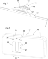
- THE figures 1 to 15 represent a covering system 2 intended to cover a pool, such as a swimming pool.
- the covering system 2 comprises a pool cover 3, and a winding device 4 configured to wind and unwind the pool cover 3 respectively in a winding direction SE and an unwinding direction SD.
- the winding device 4 is more particularly configured to wind and unwind the pool cover 3 between a deployed position in which the pool cover 3 covers all or substantially all of the pool, and a retracted position in which the pool cover 3 provides access to the pool.
- the winding device 4 may for example be submerged and arranged in a dedicated compartment 5 of the pool, and be separated from the swimming area 6 by a partition 7 (see Figure 1 ).
- the pool cover 3 is advantageously a slatted apron, also called a slatted shutter, comprising a plurality of slats 8 articulated together along axes perpendicular to the direction of movement D1 of the pool cover 3 (see Figure 2 ).
- the blades 8 are fitted into each other with sufficient mechanical play to allow them to be wound around the winding device 4, and are floating so as to be able to move along the waterline 9 in the swimming area 6.
- the pool cover 3 comprises in particular a first end portion 3a connected to the winding device 4, and a second end portion 3b opposite the first end portion 3a.
- the first end portion 3a is the first portion to be wound onto the winding device 4 and the last portion to be unwound from the winding device 4, while the second end portion 3b is the last portion to be wound onto the winding device 4 and the first portion to be unwound from the winding device 4.
- the covering system 2 comprises a locking system 10 shown more particularly on the figures 4 to 12 .
- the locking system 10 comprises a retaining element 11 fixed to the pool cover 3, and for example to the second end portion 3b of the pool cover 3.
- the retaining element 11 comprises a fixing portion 12 intended to be fixed, for example by screwing, to the pool cover 3 and a retaining portion 13 which is integral with the fixing portion 12.
- the retaining portion 13 comprises first and second retaining stops 14, 15 provided respectively with first and second stop surfaces 14.1, 15.1.
- first and second stop surfaces 14.1, 15.1 are coplanar.
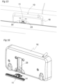
- the locking system 10 further comprises a locking device 16 comprising a fixing housing 17 configured to be fixed to a vertical wall 18 of the pool, and for example to a vertical wall of the pool which is opposite the winding device 4.
- the fixing housing 17 comprises a first housing part 17.1 configured to be fixed, for example by screwing, to the vertical wall 18 of the basin, and a second housing part 17.2, such as a covering hood, fixed to the first housing part 17.1.
- the first and second housing parts 17.1, 17.2 delimit an internal chamber 19, and the second housing part 17.2 comprises a passage opening 21 opening into the internal chamber 19.
- the passage opening 21 is provided on a front face of the fixing housing 17.
- the retaining element 11 is configured to be received in the internal chamber 19 via the passage opening 21 when the pool cover 3 is in the deployed position.
- the retaining element 11 is configured to be inserted through the passage opening 21 in an insertion direction which is parallel to the direction of movement D1 of the pool cover 3.
- the passage opening 21 has a width greater than the width of the retaining element 11 at the first and second retaining stops 14, 15.
- the locking device 16 also comprises first and second locking elements 22, 23, such as first and second locking flaps, housed in the internal chamber 19.
- the first and second locking elements 22, 23 are slidably mounted relative to the fixing housing 17 in a sliding direction D2, which extends horizontally and perpendicular to the direction of movement D1 of the pool cover 3, and between a locking configuration in which the first and second locking elements 22, 23 are brought closer to each other and are configured to cooperate respectively with the first and second retaining stops 14, 15 (when the retaining element 11 is received in the internal chamber 19) so as to lock the retaining element 11 in the fixing housing 17, and thus so as to lock the pool cover 3 in a deployed position, and a release configuration in which the first and second locking elements 22, 23 are spaced from each other and are configured to release the first and second retaining stops 14, 15 so as to allow withdrawal of the retaining element 11 from the internal chamber 19, and thus so as to allow movement of the pool cover 3 to a retracted position.
- the first and second locking elements 22, 23 extend substantially vertically, and are slidably mounted in a sliding plane which is vertical.
- the first and second locking elements 22, 23 are configured to extend partially opposite the passage opening 21 when the first and second locking elements 22, 23 occupy the locking configuration.
- the first and second locking elements 22, 23 are configured to delimit a receiving slot when they occupy the locking configuration.
- the receiving slot extends more particularly vertically.
- the first and second locking elements 22, 23 are similar to two sliding doors, and more particularly to the leaves of an elevator.
- the locking device 16 also includes a drive mechanism configured to move the first and second locking members 22, 23 between the locking configuration and the releasing configuration.
- the first and second worm screws 24, 25 extend coaxially with respect to each other, respectively have first and second screw pitches which are identical and respectively have first and second threads which extend according to first and second thread orientations which are opposite to each other.
- the first and second worm screws 24, 25 are made in a single piece.
- the rotation drive device 26 is more particularly configured to rotate the first worm 24 and the second worm 25 in a first direction of rotation when the first and second locking elements 22, 23 are moved from the locking configuration to the release configuration and to rotate the first worm 24 and the second worm 25 in a second direction of rotation, which is opposite to the first direction of rotation, when the first and second locking elements 22, 23 are moved from the release configuration to the locking configuration.
- the rotation drive device 26 comprises a drive motor 27, such as a geared motor, housed in the fixing housing 17 and configured to drive the first and second endless screws 24, 25 in rotation respectively around the first and second central longitudinal axes.
- the drive motor 27 comprises an output shaft which is rotatably coupled to the first and second worm screws 24, 25 and which is substantially coaxial with the first and second worm screws 24, 25.
- the locking device 16 further comprises a guide device configured to slidably guide the first and second locking elements 22, 23 along the sliding direction D2 when the first and second locking elements 22, 23 are moved by the drive mechanism between the release configuration and the locking configuration.
- the guide device more particularly comprises two guide rods 28 which are fixed to the fixing housing 17 and which extend parallel to the sliding direction D2, and the first and second locking elements 22, 23 are slidably mounted on the two guide rods 28.
- each of the guide rods 28 has a circular section.
- the first locking element 22 comprises two first upper guide portions 22.2 offset relative to each other in the sliding direction D2 and each provided with a first upper guide hole, and two first lower guide portions 22.3 offset from each other along the sliding direction D2 and each provided with a first lower guide hole.
- the second locking element 23 comprises two second upper guide portions 23.2 offset from each other along the sliding direction D2 and each provided with a second upper guide hole, and two second lower guide portions 23.3 offset from each other along the sliding direction D2 and each provided with a second lower guide hole.
- One of the guide rods 28 extends through the first and second upper guide holes, while the other guide rods 28 extends through the first and second lower guide holes.
- the locking system 10 further comprises a control unit 29 (see Figure 10 ) configured to control the operation of the drive mechanism.
- the control unit 29 is housed in the fixing housing 17, and comprises for example a printed circuit board equipped with a microprocessor.
- the locking system 10 further comprises a detection system, such as a contactless detection system, configured to detect when the retaining element 11 is received in the internal chamber 19, and the control unit 29 is configured to automatically control a movement of the first and second locking elements 22, 23 into the locking configuration when the detection system has detected that the retaining element 11 is received in the internal chamber 19.
- a detection system such as a contactless detection system
- the detection system may for example comprise a permanent magnet 31 fixed to the retaining element 11 (the retaining element 11 may for example be overmolded onto the permanent magnet 31), and a presence detector 32, such as a Hall effect sensor, fixed to the fixing housing 17, and more particularly to the control unit 29, and configured to detect the reception of the retaining element 11 in the internal chamber 19 when a magnetic field measured by the presence detector 32 is greater than a predetermined threshold.
- the presence detector 32 is located at least partly opposite the passage opening 21.
- the presence detector 32 is configured to send a measurement signal to the control unit 29, and the control unit 29 is configured to compare the measurement signal to a predetermined threshold value and to control a movement of the first and second locking elements 22, 23 in the locking configuration when the measurement signal is greater than or equal to the predetermined threshold value.
- the locking system 10 also comprises a communication module 33, such as a radio communication module, attached to the fixing housing 17.
- the communication module 33 more particularly comprises a receiver configured to receive an unlocking control signal transmitted by a remote terminal (such as a remote control or a smartphone), for example by Bluetooth, Wifi or any other wireless communication protocol, and the control unit 29, which is connected to the communication module 33, is configured to control a movement of the first and second locking elements 22, 23 into the release configuration when an unlocking control signal is received by the receiver.
- the unlocking control signal could be transmitted to the control unit 29 in a wired manner, for example from a control unit equipping the winding device 4.
- the locking system 10 also comprises first and second locking indicators 34, 35 configured to signal a locking state and an unlocking state of the locking system 10.
- the first and second locking indicators 34, 35 are respectively provided on the first and second locking elements 22, 23, and are configured on the one hand to be visible respectively through first and second viewing openings 36, 37 provided on the front face of the fixing housing 17, when the first and second locking elements 22, 23 occupy the locking configuration, and not to be visible respectively through the first and second viewing openings 36, 37, when the first and second locking elements 22, 23 occupy the release configuration.
- the first and second locking indicators 34, 35 may for example be formed respectively by first and second colored zones provided on the first and second locking elements 22, 23.
- the power supply of the locking device 16, and in particular of the control unit 29 and the drive motor 27, is carried out by a power supply wire 38. It is thus also possible to transmit the unlocking control signal to the locking device 16 in a wired manner (via the power supply wire 38), rather than by a wireless communication protocol.
- a method of locking the pool cover 3 will now be described with reference to figures 1 to 15 , considering that initially the first and second locking elements 22, 23 are in the release configuration, and the pool cover 3 is wound around the winding device 4 (see Figure 1 ).
- first and second locking indicators 34, 35 are visible through the first and second viewing openings 36, 37 so as to signal a locking state of the locking system 10 (see Figure 15 ).
- the locking system 10 could comprise a detection device configured to detect when the first and second locking elements 22, 23 occupy the locking configuration and/or the release configuration.
- a detection device detection could for example comprise first and second permanent magnets attached respectively to the first and second locking elements 22, 23, a first pair of Hall effect sensors configured to detect when the first and second locking elements 22, 23 occupy the locking configuration based on the detection of the magnetic fields generated respectively by the first and second permanent magnets and a second pair of Hall effect sensors configured to detect when the first and second locking elements 22, 23 occupy the release configuration based on the detection of the magnetic fields generated respectively by the first and second permanent magnets.
- the detection system could comprise at least one position sensor provided on the pool cover 3, and the control unit 29 would then be configured to automatically control a movement of the first and second locking elements 22, 23 into the locking configuration when the detection system has detected that the pool cover 3 has reached the deployed position.
- the fixing housing 17 could be envisaged to equip the fixing housing 17 with a rechargeable battery to provide the electrical power supply to the locking device 16, and in particular to the control unit 29 and the drive motor 27.
- FIG 16 represents a locking system 10 according to a second embodiment of the invention which differs from the first embodiment represented on the figures 1 to 15 essentially in that the fixing housing 17 is configured to be fixed to a vertical wall 18 of the pool which is located on the side of the winding device 4, and in that the retaining element 11 is intended to be fixed to the first end 3a of the pool cover 3.
- the passage opening 21 has a width less than the width of the retaining element 11 at the first and second retaining stops 14, 15, and opens into a lower face of the fixing housing 17.
- the retaining element 11 is configured to be inserted into the internal chamber 19, via the passage opening 21, in an insertion direction which is substantially vertical and oriented from bottom to top.
- the fixing housing 17 may for example be provided with a guide portion 41 which is located near the lower end of the passage opening 21 and which is configured to cooperate with the retaining element 11, and more particularly with the first and second retaining stops 14, 15.
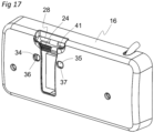
- FIG. 17 represents a locking system 10 according to a third embodiment of the invention which differs from the second embodiment shown in the figure 16 essentially in that the winding device 4 is not immersed in the basin, and in that the passage opening 21 opens into an upper face of the fixing housing 17.
- the retaining element 11 is configured to be inserted into the internal chamber 19, via the passage opening 21, in an insertion direction which is substantially vertical and oriented from top to bottom, and the guide portion 41 is located near the upper end of the passage opening 21.
Landscapes
- Engineering & Computer Science (AREA)
- Architecture (AREA)
- Civil Engineering (AREA)
- Structural Engineering (AREA)
- Lock And Its Accessories (AREA)
- Sewage (AREA)
- Casings For Electric Apparatus (AREA)
Claims (16)
- Verriegelungssystem (10) einer Beckenabdeckung (3), umfassend ein Halteelement (11), das zur Befestigung an der Beckenabdeckung (3) bestimmt ist, und eine Verriegelungsvorrichtung (16), umfassend:- ein Befestigungsgehäuse (17), das zur Befestigung an einer Beckenwand bestimmt ist, wobei das Befestigungsgehäuse (17) eine Innenkammer (19) und eine Durchgangsöffnung (21) umfasst, die in die Innenkammer (19) münden, wobei das Halteelement (11) so eingerichtet ist, dass es über die Durchgangsöffnung (21) in die Innenkammer (19) empfangen wird,- ein erstes Verriegelungselement (22) und ein zweites Verriegelungselement (23), die mindestens teilweise in der Innenkammer (19) untergebracht sind und die in Bezug auf das Befestigungsgehäuse (17) entlang einer Schieberichtung (D2) und zwischen einer Verriegelungseinrichtung, in der das erste und das zweite Verriegelungselement (22, 23) einander angenähert sind und so eingerichtet sind, dass sie mit dem Halteelement (11) zusammenwirken, verschiebbar angebracht sind, wenn das Halteelement (11) in der Innenkammer (19) empfangen wird, um das Halteelement (11) zu verriegeln, und einer Freigabeeinrichtung, in der das erste und das zweite Verriegelungselement (22, 23) voneinander entfernt und so eingerichtet sind, dass sie das Halteelement (11) freigeben, um ein Herausziehen des Halteelements (11) aus der Innenkammer (19) zuzulassen, und- einen Antriebsmechanismus, der so eingerichtet ist, dass er das erste und das zweite Verriegelungselement (22, 23) zwischen der Verriegelungseinrichtung und der Freigabeeinrichtung bewegt.
- Verriegelungssystem (10) nach Anspruch 1, das eine Führungsvorrichtung umfasst, die so eingerichtet ist, dass sie das erste und das zweite Verriegelungselement (22, 23) in Schieberichtung (D2) verschiebbar führt, wenn das erste und das zweite Verriegelungselement (22, 23) durch den Antriebsmechanismus zwischen der Freigabeeinrichtung und der Verriegelungseinrichtung bewegt werden.
- Verriegelungssystem (10) nach Anspruch 2, wobei die Führungsvorrichtung zwei Führungsstangen (28) umfasst, die am Befestigungsgehäuse (17) befestigt sind und sich im Wesentlichen parallel zur Schieberichtung (D2) erstrecken, wobei das erste und das zweite Verriegelungselement (22, 23) verschiebbar auf den beiden Führungsstangen (28) montiert sind.
- Verriegelungssystem (10) nach einem der Ansprüche 1 bis 3, wobei der Antriebsmechanismus Folgendes umfasst:- die erste und zweite Schnecke (24, 25) jeweils eine erste zentrale Längsachse und eine zweite zentrale Längsachse aufweisen, die im Wesentlichen parallel zueinander liegen, wobei die erste und zweite Schnecke (24, 25) so eingerichtet sind, dass sie mit jeweils ersten und zweiten Gewindeantriebsteilen zusammenarbeiten, die an den ersten und zweiten Verriegelungselementen (22, 23) vorgesehen sind, und- eine Drehantriebsvorrichtung (26), die so eingerichtet ist, dass sie die erste Schnecke (24) um die erste zentrale Längsachse herum dreht und die zweite Schnecke (25) um die zweite zentrale Längsachse herum dreht.
- Verriegelungssystem (10) nach Anspruch 4, wobei die Drehantriebsvorrichtung (26) so eingerichtet ist, dass sie die erste Schnecke (24) und die zweite Schnecke (25) in einer ersten Drehrichtung dreht, wenn das erste und das zweite Verriegelungselement (22, 23) aus der Verriegelungseinrichtung in die Freigabeeinrichtung bewegt werden, und um die erste Schnecke (24) und die zweite Schnecke (25) in einer zweiten Drehrichtung, die der ersten Drehrichtung entgegengesetzt ist, zu drehen, wenn das erste und das zweite Verriegelungselement (22, 23) aus der Freigabeeinrichtung in die Verriegelungseinrichtung bewegt werden.
- Verriegelungssystem (10) nach Anspruch 4 oder 5, wobei sich die erste und zweite Schnecke (24, 25) im Wesentlichen koaxial zueinander erstrecken.
- Verriegelungssystem (10) nach einem der Ansprüche 4 bis 6, wobei die erste und zweite Schnecke (24, 25) in einem Stück ausgeführt sind.
- Verriegelungssystem (10) nach einem der Ansprüche 4 bis 7, wobei die Drehantriebsvorrichtung (26) einen im Befestigungsgehäuse (17) gelagerten Antriebsmotor (27) umfasst, der so eingerichtet ist, dass er die erste und zweite Schnecke (24, 25) um die erste und zweite zentrale Längsachse dreht.
- Verriegelungssystem (10) nach einem der Ansprüche 1 bis 8, das eine Steuereinheit (29) umfasst, die zur Steuerung des Betriebs des Antriebsmechanismus eingerichtet ist.
- Verriegelungssystem (10) nach Anspruch 9, das ferner ein Erkennungssystem umfasst, das so eingerichtet ist, dass es erkennt, wenn das Halteelement (11) in der Innenkammer (19) empfangen wird, wobei die Steuereinheit (29) so eingerichtet ist, dass sie automatisch eine Bewegung des ersten und zweiten Verriegelungselements (22, 23) in die Verriegelungseinrichtung steuert, wenn das Erkennungssystem erkannt hat, dass das Halteelement (11) in der Innenkammer (19) empfangen wird.
- Verriegelungssystem (10) nach Anspruch 10, wobei das Erkennungssystem mindestens einen am Halteelement (11) befestigten Permanentmagneten (31) und einen am Befestigungsgehäuse (17) befestigten und zum Messen eines Magnetfelds eingerichteten Anwesenheitsdetektor (32) umfasst, wobei der Anwesenheitsdetektor (32) so eingerichtet ist, dass er den Empfang des Halteelements (11) in der Innenkammer (19) erkennt, wenn ein vom Anwesenheitsdetektor (32) gemessenes Magnetfeld über einem vorgegebenen Schwellenwert liegt.
- Verriegelungssystem (10) nach Anspruch 11, das ein Kommunikationsmodul (33) umfasst, das am Befestigungsgehäuse (17) befestigt ist und einen Empfänger umfasst, der so eingerichtet ist, dass er ein von einem entfernten Endgerät gesendetes Entriegelungsbefehlssignal empfängt, wobei die Steuereinheit (29) mit dem Kommunikationsmodul (33) verbunden ist und so eingerichtet ist, dass sie eine Bewegung der ersten und zweiten Verriegelungselemente (22, 23) steuert in der Freigabeeinrichtung, wenn ein Entriegelungsbefehlssignal vom Empfänger empfangen wird.
- Verriegelungssystem (10) nach einem der Ansprüche 1 bis 12, das mindestens eine Verriegelungsanzeige (34, 35) umfasst, die so eingerichtet ist, dass sie einen Verriegelungs- und/oder Entriegelungszustand des Verriegelungssystems (10) signalisiert.
- Verriegelungssystem (10) nach Anspruch 13, wobei das erste und das zweite Verriegelungselement (22, 23) jeweils erste und zweite Verriegelungsanzeigen (34, 35) umfassen, die so eingerichtet sind, dass sie jeweils durch die erste und zweite Sichtöffnungen (36, 37) sichtbar sind, die am Befestigungsgehäuse (17) vorgesehen sind, wenn das erste und das zweite Verriegelungselement (22, 23) die Verriegelungseinrichtung einnehmen.
- Verriegelungssystem (10) nach einem der Ansprüche 1 bis 14, wobei das Halteelement (11) erste und zweite Halteanschläge (14, 15) umfasst, wobei das erste und zweite Verriegelungselement (22, 23) so eingerichtet sind, dass es mit dem ersten und zweiten Halteanschlag (14, 15) zusammenarbeitet, wenn das Halteelement (11) in der Innenkammer (19) empfangen wird und das erste und zweite Verriegelungselement (22, 23) die Verriegelungseinrichtung einnehmen und so eingerichtet sein, dass sie den ersten und zweiten Halteanschlag (14, 15) freigeben, wenn das erste und zweite Verriegelungselement (22, 23) die Freigabeeinrichtung einnehmen.
- Abdecksystem (2), das so eingerichtet ist, dass es ein Becken abdeckt, das Abdecksystem (2) umfassend:- eine Beckenabdeckung (3), umfassend einen ersten Endabschnitt (3a) und einen zweiten Endabschnitt (3b), der dem ersten Endabschnitt (3a) gegenübersteht,- eine Wickelvorrichtung (4), die so eingerichtet ist, dass sie mit dem ersten Endabschnitt (3a) der Beckenabdeckung (3) verbunden ist, und die so eingerichtet ist, dass sie die Beckenabdeckung (3) zwischen einer ausgeklappten Position, in der die Beckenabdeckung (3) das Becken bedeckt, und einer eingefahrenen Position, in der die Beckenabdeckung (3) den Zugang zum Becken freigibt, auf- und abrollt, und- ein Verriegelungssystem (10) nach einem der vorhergehenden Ansprüche, wobei das Halteelement (11) an der Beckenabdeckung (3) und das Befestigungsgehäuse (17) an einer Beckenwand befestigt ist.
Applications Claiming Priority (1)
| Application Number | Priority Date | Filing Date | Title |
|---|---|---|---|
| FR2210669A FR3140896B1 (fr) | 2022-10-17 | 2022-10-17 | Système de verrouillage d’une couverture de bassin |
Publications (3)
| Publication Number | Publication Date |
|---|---|
| EP4357559A1 EP4357559A1 (de) | 2024-04-24 |
| EP4357559C0 EP4357559C0 (de) | 2025-06-11 |
| EP4357559B1 true EP4357559B1 (de) | 2025-06-11 |
Family
ID=84370587
Family Applications (1)
| Application Number | Title | Priority Date | Filing Date |
|---|---|---|---|
| EP23203144.3A Active EP4357559B1 (de) | 2022-10-17 | 2023-10-12 | Verriegelungssystem für eine beckenabdeckung |
Country Status (3)
| Country | Link |
|---|---|
| EP (1) | EP4357559B1 (de) |
| ES (1) | ES3037080T3 (de) |
| FR (1) | FR3140896B1 (de) |
Family Cites Families (4)
| Publication number | Priority date | Publication date | Assignee | Title |
|---|---|---|---|---|
| US9097028B2 (en) | 2012-07-03 | 2015-08-04 | Maytronics Ltd. | Pool cover automatic locking and unlocking system and method |
| FR3012834B1 (fr) * | 2013-11-04 | 2016-09-16 | Annonay Productions France | Dispositif de verrouillage d'une couverture de bassin de piscine dans une position deployee |
| EP3196384A1 (de) * | 2016-01-25 | 2017-07-26 | A.S.Pool | Verriegelungssystem einer beckenabdeckung |
| FR3098536B1 (fr) * | 2019-07-12 | 2021-07-30 | A S Pool | Système de verrouillage d’une couverture de bassin |
-
2022
- 2022-10-17 FR FR2210669A patent/FR3140896B1/fr active Active
-
2023
- 2023-10-12 EP EP23203144.3A patent/EP4357559B1/de active Active
- 2023-10-12 ES ES23203144T patent/ES3037080T3/es active Active
Also Published As
| Publication number | Publication date |
|---|---|
| FR3140896B1 (fr) | 2024-10-18 |
| ES3037080T3 (en) | 2025-09-26 |
| EP4357559C0 (de) | 2025-06-11 |
| FR3140896A1 (fr) | 2024-04-19 |
| EP4357559A1 (de) | 2024-04-24 |
Similar Documents
| Publication | Publication Date | Title |
|---|---|---|
| EP3763899B1 (de) | Verriegelungssystem einer beckenabdeckung | |
| EP2991201B1 (de) | Motorisierte betätigungsvorrichtung zur betätigung eines mobilen bildschirms aus einer aufrollbaren leinwand einer fensterabdeckvorrichtung oder einer projektionswand | |
| EP4357559B1 (de) | Verriegelungssystem für eine beckenabdeckung | |
| EP1106751B1 (de) | Flexible Hecke für Schwimmbäder | |
| EP3957817B1 (de) | Rollladenstruktur und montageverfahren | |
| FR2911893A1 (fr) | Piscine comprenant un dispositif d'enroulement/deroulement d'une couverture logee dans une marche d'escalier | |
| EP2868842B1 (de) | Verriegelungsvorrichtung einer Schwimmbadabdeckung in entfaltetem Zustand | |
| FR3098771A1 (fr) | Becquet destiné à être rapporté sur le hayon d’un véhicule automobile | |
| EP2616890B1 (de) | Extraflacher eigenständiger kommunikationssensor | |
| EP2709940A1 (de) | Lastenhebevorrichtung | |
| EP1977070B1 (de) | Stützvorrichtung für rollo und mit solch einer vorrichtung zu versehene rolloanordnung | |
| EP2066856B1 (de) | Schwimmbeckenabdeckung mit aufrollmechanismus | |
| EP3952624B1 (de) | Modulare elektronische anordnung und mobiles videosystem mit einer solchen anordnung | |
| FR2913709A1 (fr) | Dispositif de verrouillage d'une couverture de piscine comprenant des moyens de retenue d'un element d'accrochage mobile entre une position verrouillee et une position deverrouillee. | |
| EP3196384A1 (de) | Verriegelungssystem einer beckenabdeckung | |
| FR2636092A1 (fr) | Dispositif de verrouillage et deverrouillage automatique de la lame finale d'un rideau ou grille roulant en position de fermeture | |
| EP2018462B1 (de) | Tor mit flexiblem torblatt und vorverdrahtetem steuerkasten | |
| FR3047031A1 (fr) | Systeme de verrouillage d’une couverture de bassin | |
| EP3254319B1 (de) | Stationärer schutz zur aufbewahrung von mindestens einem energiespeicherelement | |
| FR2952445A1 (fr) | Ecran de projection enroulable muni d'un dispositif d'integration dans un plenum d'un plafond | |
| FR2967184A1 (fr) | Kit d'habillage pour un systeme d'enroulement d'une couverture de piscine | |
| FR2877980A1 (fr) | Dispositif de verrouillage pour portillon d'acces a une zone securisee notamment une piscine | |
| FR2907484A1 (fr) | Dispositif de blocage en position fermee d'un vantail coulissant dans un dormant | |
| FR2888609A3 (fr) | Rideau electrique pour fenetre | |
| EP3272617A1 (de) | Gepäck und anordung aus gepäck und einer befestigungsklemme |
Legal Events
| Date | Code | Title | Description |
|---|---|---|---|
| PUAI | Public reference made under article 153(3) epc to a published international application that has entered the european phase |
Free format text: ORIGINAL CODE: 0009012 |
|
| STAA | Information on the status of an ep patent application or granted ep patent |
Free format text: STATUS: THE APPLICATION HAS BEEN PUBLISHED |
|
| AK | Designated contracting states |
Kind code of ref document: A1 Designated state(s): AL AT BE BG CH CY CZ DE DK EE ES FI FR GB GR HR HU IE IS IT LI LT LU LV MC ME MK MT NL NO PL PT RO RS SE SI SK SM TR |
|
| STAA | Information on the status of an ep patent application or granted ep patent |
Free format text: STATUS: REQUEST FOR EXAMINATION WAS MADE |
|
| 17P | Request for examination filed |
Effective date: 20241004 |
|
| RBV | Designated contracting states (corrected) |
Designated state(s): AL AT BE BG CH CY CZ DE DK EE ES FI FR GB GR HR HU IE IS IT LI LT LU LV MC ME MK MT NL NO PL PT RO RS SE SI SK SM TR |
|
| GRAP | Despatch of communication of intention to grant a patent |
Free format text: ORIGINAL CODE: EPIDOSNIGR1 |
|
| STAA | Information on the status of an ep patent application or granted ep patent |
Free format text: STATUS: GRANT OF PATENT IS INTENDED |
|
| GRAJ | Information related to disapproval of communication of intention to grant by the applicant or resumption of examination proceedings by the epo deleted |
Free format text: ORIGINAL CODE: EPIDOSDIGR1 |
|
| STAA | Information on the status of an ep patent application or granted ep patent |
Free format text: STATUS: REQUEST FOR EXAMINATION WAS MADE |
|
| RIC1 | Information provided on ipc code assigned before grant |
Ipc: E05B 47/00 20060101ALI20250106BHEP Ipc: E05B 15/10 20060101ALI20250106BHEP Ipc: E05B 15/00 20060101ALI20250106BHEP Ipc: E04H 4/08 20060101AFI20250106BHEP |
|
| INTG | Intention to grant announced |
Effective date: 20250117 |
|
| INTC | Intention to grant announced (deleted) | ||
| GRAP | Despatch of communication of intention to grant a patent |
Free format text: ORIGINAL CODE: EPIDOSNIGR1 |
|
| STAA | Information on the status of an ep patent application or granted ep patent |
Free format text: STATUS: GRANT OF PATENT IS INTENDED |
|
| INTG | Intention to grant announced |
Effective date: 20250312 |
|
| GRAS | Grant fee paid |
Free format text: ORIGINAL CODE: EPIDOSNIGR3 |
|
| GRAA | (expected) grant |
Free format text: ORIGINAL CODE: 0009210 |
|
| STAA | Information on the status of an ep patent application or granted ep patent |
Free format text: STATUS: THE PATENT HAS BEEN GRANTED |
|
| AK | Designated contracting states |
Kind code of ref document: B1 Designated state(s): AL AT BE BG CH CY CZ DE DK EE ES FI FR GB GR HR HU IE IS IT LI LT LU LV MC ME MK MT NL NO PL PT RO RS SE SI SK SM TR |
|
| REG | Reference to a national code |
Ref country code: GB Ref legal event code: FG4D Free format text: NOT ENGLISH |
|
| REG | Reference to a national code |
Ref country code: CH Ref legal event code: EP |
|
| REG | Reference to a national code |
Ref country code: DE Ref legal event code: R096 Ref document number: 602023003945 Country of ref document: DE |
|
| REG | Reference to a national code |
Ref country code: IE Ref legal event code: FG4D Free format text: LANGUAGE OF EP DOCUMENT: FRENCH |
|
| U01 | Request for unitary effect filed |
Effective date: 20250624 |
|
| U07 | Unitary effect registered |
Designated state(s): AT BE BG DE DK EE FI FR IT LT LU LV MT NL PT RO SE SI Effective date: 20250701 |
|
| REG | Reference to a national code |
Ref country code: ES Ref legal event code: FG2A Ref document number: 3037080 Country of ref document: ES Kind code of ref document: T3 Effective date: 20250926 |
|
| PG25 | Lapsed in a contracting state [announced via postgrant information from national office to epo] |
Ref country code: GR Free format text: LAPSE BECAUSE OF FAILURE TO SUBMIT A TRANSLATION OF THE DESCRIPTION OR TO PAY THE FEE WITHIN THE PRESCRIBED TIME-LIMIT Effective date: 20250912 Ref country code: NO Free format text: LAPSE BECAUSE OF FAILURE TO SUBMIT A TRANSLATION OF THE DESCRIPTION OR TO PAY THE FEE WITHIN THE PRESCRIBED TIME-LIMIT Effective date: 20250911 |
|
| PG25 | Lapsed in a contracting state [announced via postgrant information from national office to epo] |
Ref country code: HR Free format text: LAPSE BECAUSE OF FAILURE TO SUBMIT A TRANSLATION OF THE DESCRIPTION OR TO PAY THE FEE WITHIN THE PRESCRIBED TIME-LIMIT Effective date: 20250611 |
|
| PG25 | Lapsed in a contracting state [announced via postgrant information from national office to epo] |
Ref country code: RS Free format text: LAPSE BECAUSE OF FAILURE TO SUBMIT A TRANSLATION OF THE DESCRIPTION OR TO PAY THE FEE WITHIN THE PRESCRIBED TIME-LIMIT Effective date: 20250911 |
|
| U20 | Renewal fee for the european patent with unitary effect paid |
Year of fee payment: 3 Effective date: 20251015 |
|
| PG25 | Lapsed in a contracting state [announced via postgrant information from national office to epo] |
Ref country code: IS Free format text: LAPSE BECAUSE OF FAILURE TO SUBMIT A TRANSLATION OF THE DESCRIPTION OR TO PAY THE FEE WITHIN THE PRESCRIBED TIME-LIMIT Effective date: 20251011 |
|
| PG25 | Lapsed in a contracting state [announced via postgrant information from national office to epo] |
Ref country code: SM Free format text: LAPSE BECAUSE OF FAILURE TO SUBMIT A TRANSLATION OF THE DESCRIPTION OR TO PAY THE FEE WITHIN THE PRESCRIBED TIME-LIMIT Effective date: 20250611 |
|
| PG25 | Lapsed in a contracting state [announced via postgrant information from national office to epo] |
Ref country code: CZ Free format text: LAPSE BECAUSE OF FAILURE TO SUBMIT A TRANSLATION OF THE DESCRIPTION OR TO PAY THE FEE WITHIN THE PRESCRIBED TIME-LIMIT Effective date: 20250611 |
|
| PG25 | Lapsed in a contracting state [announced via postgrant information from national office to epo] |
Ref country code: PL Free format text: LAPSE BECAUSE OF FAILURE TO SUBMIT A TRANSLATION OF THE DESCRIPTION OR TO PAY THE FEE WITHIN THE PRESCRIBED TIME-LIMIT Effective date: 20250611 |
|
| PG25 | Lapsed in a contracting state [announced via postgrant information from national office to epo] |
Ref country code: SK Free format text: LAPSE BECAUSE OF FAILURE TO SUBMIT A TRANSLATION OF THE DESCRIPTION OR TO PAY THE FEE WITHIN THE PRESCRIBED TIME-LIMIT Effective date: 20250611 |
|
| PGFP | Annual fee paid to national office [announced via postgrant information from national office to epo] |
Ref country code: ES Payment date: 20260114 Year of fee payment: 3 |
|
| PLBE | No opposition filed within time limit |
Free format text: ORIGINAL CODE: 0009261 |
|
| STAA | Information on the status of an ep patent application or granted ep patent |
Free format text: STATUS: NO OPPOSITION FILED WITHIN TIME LIMIT |
|
| REG | Reference to a national code |
Ref country code: CH Ref legal event code: L10 Free format text: ST27 STATUS EVENT CODE: U-0-0-L10-L00 (AS PROVIDED BY THE NATIONAL OFFICE) Effective date: 20260423 |