EP4357603A1 - Steuerungsverfahren für verbrennungssystem, verbrennungssystem und dieselmotor - Google Patents
Steuerungsverfahren für verbrennungssystem, verbrennungssystem und dieselmotor Download PDFInfo
- Publication number
- EP4357603A1 EP4357603A1 EP22823771.5A EP22823771A EP4357603A1 EP 4357603 A1 EP4357603 A1 EP 4357603A1 EP 22823771 A EP22823771 A EP 22823771A EP 4357603 A1 EP4357603 A1 EP 4357603A1
- Authority
- EP
- European Patent Office
- Prior art keywords
- cylinder pressure
- cylinder
- main fuel
- fuel injection
- time
- Prior art date
- Legal status (The legal status is an assumption and is not a legal conclusion. Google has not performed a legal analysis and makes no representation as to the accuracy of the status listed.)
- Pending
Links
Images


Classifications
-
- F—MECHANICAL ENGINEERING; LIGHTING; HEATING; WEAPONS; BLASTING
- F02—COMBUSTION ENGINES; HOT-GAS OR COMBUSTION-PRODUCT ENGINE PLANTS
- F02D—CONTROLLING COMBUSTION ENGINES
- F02D41/00—Electrical control of supply of combustible mixture or its constituents
- F02D41/30—Controlling fuel injection
- F02D41/38—Controlling fuel injection of the high pressure type
- F02D41/40—Controlling fuel injection of the high pressure type with means for controlling injection timing or duration
- F02D41/402—Multiple injections
-
- F—MECHANICAL ENGINEERING; LIGHTING; HEATING; WEAPONS; BLASTING
- F02—COMBUSTION ENGINES; HOT-GAS OR COMBUSTION-PRODUCT ENGINE PLANTS
- F02D—CONTROLLING COMBUSTION ENGINES
- F02D35/00—Controlling engines, dependent on conditions exterior or interior to engines, not otherwise provided for
- F02D35/02—Controlling engines, dependent on conditions exterior or interior to engines, not otherwise provided for on interior conditions
- F02D35/023—Controlling engines, dependent on conditions exterior or interior to engines, not otherwise provided for on interior conditions by determining the cylinder pressure
-
- F—MECHANICAL ENGINEERING; LIGHTING; HEATING; WEAPONS; BLASTING
- F02—COMBUSTION ENGINES; HOT-GAS OR COMBUSTION-PRODUCT ENGINE PLANTS
- F02D—CONTROLLING COMBUSTION ENGINES
- F02D35/00—Controlling engines, dependent on conditions exterior or interior to engines, not otherwise provided for
- F02D35/02—Controlling engines, dependent on conditions exterior or interior to engines, not otherwise provided for on interior conditions
- F02D35/028—Controlling engines, dependent on conditions exterior or interior to engines, not otherwise provided for on interior conditions by determining the combustion timing or phasing
-
- F—MECHANICAL ENGINEERING; LIGHTING; HEATING; WEAPONS; BLASTING
- F02—COMBUSTION ENGINES; HOT-GAS OR COMBUSTION-PRODUCT ENGINE PLANTS
- F02D—CONTROLLING COMBUSTION ENGINES
- F02D41/00—Electrical control of supply of combustible mixture or its constituents
- F02D41/02—Circuit arrangements for generating control signals
- F02D41/14—Introducing closed-loop corrections
- F02D41/1401—Introducing closed-loop corrections characterised by the control or regulation method
- F02D41/1406—Introducing closed-loop corrections characterised by the control or regulation method with use of a optimisation method, e.g. iteration
-
- F—MECHANICAL ENGINEERING; LIGHTING; HEATING; WEAPONS; BLASTING
- F02—COMBUSTION ENGINES; HOT-GAS OR COMBUSTION-PRODUCT ENGINE PLANTS
- F02D—CONTROLLING COMBUSTION ENGINES
- F02D41/00—Electrical control of supply of combustible mixture or its constituents
- F02D41/30—Controlling fuel injection
- F02D41/38—Controlling fuel injection of the high pressure type
- F02D41/3809—Common rail control systems
- F02D41/3827—Common rail control systems for diesel engines
-
- F—MECHANICAL ENGINEERING; LIGHTING; HEATING; WEAPONS; BLASTING
- F02—COMBUSTION ENGINES; HOT-GAS OR COMBUSTION-PRODUCT ENGINE PLANTS
- F02D—CONTROLLING COMBUSTION ENGINES
- F02D41/00—Electrical control of supply of combustible mixture or its constituents
- F02D41/30—Controlling fuel injection
- F02D41/38—Controlling fuel injection of the high pressure type
- F02D41/3809—Common rail control systems
- F02D41/3836—Controlling the fuel pressure
-
- F—MECHANICAL ENGINEERING; LIGHTING; HEATING; WEAPONS; BLASTING
- F02—COMBUSTION ENGINES; HOT-GAS OR COMBUSTION-PRODUCT ENGINE PLANTS
- F02D—CONTROLLING COMBUSTION ENGINES
- F02D41/00—Electrical control of supply of combustible mixture or its constituents
- F02D41/30—Controlling fuel injection
- F02D41/38—Controlling fuel injection of the high pressure type
- F02D41/40—Controlling fuel injection of the high pressure type with means for controlling injection timing or duration
-
- F—MECHANICAL ENGINEERING; LIGHTING; HEATING; WEAPONS; BLASTING
- F02—COMBUSTION ENGINES; HOT-GAS OR COMBUSTION-PRODUCT ENGINE PLANTS
- F02M—SUPPLYING COMBUSTION ENGINES IN GENERAL WITH COMBUSTIBLE MIXTURES OR CONSTITUENTS THEREOF
- F02M45/00—Fuel-injection apparatus characterised by having a cyclic delivery of specific time/pressure or time/quantity relationship
- F02M45/12—Fuel-injection apparatus characterised by having a cyclic delivery of specific time/pressure or time/quantity relationship providing a continuous cyclic delivery with variable pressure
-
- F—MECHANICAL ENGINEERING; LIGHTING; HEATING; WEAPONS; BLASTING
- F02—COMBUSTION ENGINES; HOT-GAS OR COMBUSTION-PRODUCT ENGINE PLANTS
- F02D—CONTROLLING COMBUSTION ENGINES
- F02D2200/00—Input parameters for engine control
- F02D2200/02—Input parameters for engine control the parameters being related to the engine
- F02D2200/06—Fuel or fuel supply system parameters
- F02D2200/0602—Fuel pressure
-
- F—MECHANICAL ENGINEERING; LIGHTING; HEATING; WEAPONS; BLASTING
- F02—COMBUSTION ENGINES; HOT-GAS OR COMBUSTION-PRODUCT ENGINE PLANTS
- F02D—CONTROLLING COMBUSTION ENGINES
- F02D2200/00—Input parameters for engine control
- F02D2200/02—Input parameters for engine control the parameters being related to the engine
- F02D2200/10—Parameters related to the engine output, e.g. engine torque or engine speed
- F02D2200/101—Engine speed
-
- F—MECHANICAL ENGINEERING; LIGHTING; HEATING; WEAPONS; BLASTING
- F02—COMBUSTION ENGINES; HOT-GAS OR COMBUSTION-PRODUCT ENGINE PLANTS
- F02D—CONTROLLING COMBUSTION ENGINES
- F02D41/00—Electrical control of supply of combustible mixture or its constituents
- F02D41/30—Controlling fuel injection
- F02D41/38—Controlling fuel injection of the high pressure type
- F02D41/40—Controlling fuel injection of the high pressure type with means for controlling injection timing or duration
- F02D41/402—Multiple injections
- F02D41/403—Multiple injections with pilot injections
-
- F—MECHANICAL ENGINEERING; LIGHTING; HEATING; WEAPONS; BLASTING
- F02—COMBUSTION ENGINES; HOT-GAS OR COMBUSTION-PRODUCT ENGINE PLANTS
- F02D—CONTROLLING COMBUSTION ENGINES
- F02D41/00—Electrical control of supply of combustible mixture or its constituents
- F02D41/30—Controlling fuel injection
- F02D41/38—Controlling fuel injection of the high pressure type
- F02D41/40—Controlling fuel injection of the high pressure type with means for controlling injection timing or duration
- F02D41/402—Multiple injections
- F02D41/405—Multiple injections with post injections
Definitions
- the present application relates to the technical field of diesel engines, and in particular to a method for controlling a combustion system, the combustion system and a diesel engine.
- the main combustion method of a diesel engine in the conventional technology is diffusion combustion, and the combustion speed is largely limited by the oil-gas mixing speed.
- a high-pressure common rail diesel engine generally uses a single main fuel injection.
- the entrainment effect of single high-pressure injection mainly occurs in the atomization area, the entrainment effect is weakened in the middle of a fuel beam, and the oil-gas mixing effect is poor.
- the object of the present application is to provide a method for controlling a combustion system, the combustion system and a diesel engine, so as to improve fuel-air mixing uniformity after fuel injection.
- a method for controlling a combustion system includes a piston, an injector, and a cylinder, the piston is configured to reciprocate up and down in the cylinder, the injector is configured to execute at least a first main fuel injection and a second main fuel injection in sequence during each movement cycle of the piston, and the injector is configured to continuously inject fuel during a process from the first main fuel injection to the second main fuel injection; an injection pressure when a velocity of the fuel injected by the injector is highest during the first main fuel injection executed by the injector is a first injection pressure, and an injection pressure when a velocity of the fuel injected by the injector is highest during the second main fuel injection executed by the injector is a second injection pressure;
- determining the duration of the first main fuel injection and the first injection pressure to allow the cylinder pressure to reach the cylinder pressure upper threshold at least at partial moment during the first main fuel injection includes: iteratively adjusting at least one of, a start time and an end time of the first main fuel injection, and current first injection pressure, until the cylinder pressure reaches the cylinder pressure upper threshold at least at partial moment during the first main fuel injection, a crankshaft angle when the cylinder pressure reaches the cylinder pressure upper threshold for a first time does not exceed a first angle, and an angle that the crankshaft has rotated during a period when the cylinder pressure rises from the first cylinder pressure to the cylinder pressure upper threshold is not less than a second preset rotation angle, in a case that the cylinder pressure never reaches the cylinder pressure upper threshold during the first main fuel injection; specifically, a corresponding cylinder volume when the cylinder pressure is equal to the first cylinder pressure is the same as a corresponding cylinder volume when the
- a timing when the injector starts the first main fuel injection is a first time t 1
- a timing when a velocity of the fuel injected by the injector is lowest between the first main fuel injection and the second main fuel injection is a second time t 2
- the first injection pressure is P 1 ; that, iteratively adjusting at least one of the start time and the end time of the first main fuel injection, and the current first injection pressure until the cylinder pressure reaches the cylinder pressure upper threshold at least at partial moment during the first main fuel injection, the crankshaft angle when the cylinder pressure reaches the cylinder pressure upper threshold for the first time does not exceed the first angle, and the angle that the crankshaft has rotated during the period when the cylinder pressure rises from the first cylinder pressure to the cylinder pressure upper threshold is not less than the second preset rotation angle, in the case that the cylinder pressure never reaches the cylinder pressure upper threshold during the first main fuel injection, includes:
- the increasing the first injection pressure P 1 , and/or, wholly reducing the difference between the second time t 2 and the first time t 1 includes:
- the method further includes increasing the first injection pressure P 1 by the first set value, and adjusting the first time t 1 and/or the second time t 2 to wholly reduce the difference between the second time t 2 and the first time t 1 by a second set value if n>5%.
- the method further includes:
- the second injection pressure is P 2 , that iteratively adjusting at least one of the duration of the second main fuel injection and the second injection pressure, to allow the change rate of the curve slopes of the cylinder pressure change curve to be within the set range of slope change rates at any time point during the period when the cylinder pressure drops from the cylinder pressure upper threshold to the set cylinder pressure in the second main fuel injection, and to allow the angle that the crankshaft has rotated during the period when the cylinder pressure drops from the cylinder pressure upper threshold to the set cylinder pressure to be not less than the first preset rotation angle, includes: in a case that ⁇ 1 ⁇ n ;
- a timing when the injector ends the second main fuel injection is a third time t 3 , if k max ⁇ k a , the method for controlling a combustion system further includes:
- the method for controlling a combustion system further includes maintaining the third time t 3 constant in a case that ⁇ 2 ⁇ m .
- a combustion system for implementing the method for controlling a combustion system described above.
- the combustion system includes a piston, an injector, a cylinder and a controller, the controller is configured to control the injector to execute at least the first main fuel injection and the second main fuel injection in sequence during each movement cycle of the piston, and the injector is configured to continuously inject fuel during the process from the first main fuel injection to the second main fuel injection;
- a diesel engine is provided according to the present application, and includes the combustion system described above.
- the method for controlling the combustion system, the combustion system and the diesel engine are provided according to the present application.
- the method for controlling the combustion system can superimpose spatial intensities of entrainment effects of high-speed oil beams of the two main fuel injections in the cylinder through the two main fuel injections, realizing two organizations of the oil beams to the flow field in the cylinder, strengthening the turbulence in the cylinder, improving the oil-gas mixing rate in the cylinder, and effectively improving the combustion speed and air utilization rate in the middle and late combustion stages.
- the cylinder pressure is ensured to reach the cylinder pressure upper threshold at least at partial moment during the first main fuel injection by determining the duration of the first main fuel injection and the first injection pressure.
- At least one of the duration of the second main fuel injection and the second injection pressure is iteratively adjusted, so that the change rate of the curve slopes of the cylinder pressure change curve is within the set range of slope change rates at any time point during the period when the cylinder pressure drops from the cylinder pressure upper threshold to the set cylinder pressure in the second main fuel injection, and the corresponding angle that the crankshaft has rotated is not less than the first preset rotation angle during the period when the cylinder pressure drops from the cylinder pressure upper threshold to the set cylinder pressure, which can ensure an optimal superposition effect of space entrainments and ensure an optimal power output of the diesel engine.
- orientations or positional relationships indicated by terms such as “center”, “up”, “down”, “left”, “right”, “vertical”, “horizontal”, “inside” and “outside” are based on the orientations or position relationships shown in the accompanying drawings, and are only for the convenience of describing the present application and simplifying the description, rather than indicating or implying that devices or elements referred to must have specific orientations, or must be constructed and operated in specific orientations, and thus should not be understood as limitations to the present application.
- terms “first” and “second” are only used for description, and should not be understood as indicating or implying relative importance.
- the terms “first position” and “second position” represent two different positions.
- first feature being “on”, “above” and “over” the second feature includes that the first feature is directly above and obliquely above the second feature, or simply indicate that the first feature is horizontally higher than the second feature.
- first feature being “below”, “under” and “beneath” the second feature includes that the first feature is directly below and obliquely below the second feature, or simply indicate that the first feature is horizontally lower than the second feature.
- mount should be understood in a broad sense, for example, may be a fixed connection, a detachable connection, or an integrated connections; may be a mechanical connection or an electric connection; may be a direct connection, or an indirect connection through an intermediary, and may be an internal connection of two elements.
- mount may be a fixed connection, a detachable connection, or an integrated connections; may be a mechanical connection or an electric connection; may be a direct connection, or an indirect connection through an intermediary, and may be an internal connection of two elements.
- the embodiment provides a combustion control system.
- the combustion control system includes a piston, an injector and a cylinder.
- the piston can reciprocate up and down in the cylinder, and the injector is used to inject fuel into a combustion chamber with the piston.
- the combustion control system also includes a controller, the controller is configured to control the injector to execute at least a first main fuel injection and a second main fuel injection in sequence during each movement cycle of the piston, and the injector is configured to continuously inject fuel during a process from the first main fuel injection to the second main fuel injection. Velocities of the fuel injected by the injector during the first main fuel injection and the second main fuel injection are not lower than a set value.
- a velocity of the fuel injected by the injector between the first main fuel injection and the second main fuel injection is lower than the set value.
- the controller may be connected to a control valve arranged in a fuel supply pipeline that supplies fuel to the injector, so as to control the injection pressure of the injector by controlling the control current of the control valve, thereby the efficiency of the fuel injected by the injector is adjusted.
- the controller is configured to determine duration of the first main fuel injection and a first injection pressure, so that the cylinder pressure can reach a cylinder pressure upper threshold at least at partial moment during the first main fuel injection.
- the controller is configured to iteratively adjust at least one of duration of the second main fuel injection and a second injection pressure, so that a change rate of curve slopes of a cylinder pressure change curve during a period when the cylinder pressure drops from the cylinder pressure upper threshold to a set cylinder pressure is within a set range of slope change rates at any time point, and an angle that a crankshaft has rotated during the period when the cylinder pressure drops from the cylinder pressure upper threshold to the set cylinder pressure is not less than a first preset rotation angle, in the second main fuel injection.
- the specific implementation process of the controller is detailed below.
- the injector by controlling the injector to execute two main fuel injections during the movement cycle of the piston and continue auxiliary injection during the two main fuel injections, spatial intensities of the entrainment effects of high-speed oil beams of the two main fuel injections can be superimposed in the cylinder, realizing two organizations of the oil beams to the flow field in the cylinder, strengthening the turbulence in the cylinder, and improving the oil-gas mixing rate in the cylinder, and effectively improving the combustion speed and air utilization rate in the cylinder in the middle and late combustion stages.
- the cylinder pressure is ensured to at least reach the cylinder pressure upper threshold by determining the duration of the first main fuel injection and the first injection pressure.
- the change rate of the curve slope of the cylinder pressure change curve is within the set range of slope change rates at any time point, and the angle that the crankshaft has rotated is not less than the first preset rotation angle, which can ensure the optimal superposition effect of space entrainments and ensure the optimal power output of the diesel engine.
- a diesel engine is provided according to the embodiment, and the diesel engine includes the combustion system according to Embodiment 1.
- the diesel engine has the beneficial effects of the combustion system according to Embodiment 1.
- a method for controlling a combustion system is provided according to the embodiment, and the method can be implemented through the combustion system according to Embodiment 1.
- the method for controlling a combustion system includes the following steps S100 to S200.
- S100 determining the duration of the first main fuel injection and the first injection pressure to allow the cylinder pressure to reach the cylinder pressure upper threshold at least at partial moment during the first main fuel injection.
- S200 iteratively adjusting at least one of the duration of the second main fuel injection and the second injection pressure, to allow the change rate of the curve slopes of the cylinder pressure change curve to be within the set range of slope change rates at each time point during the period when the cylinder pressure drops from the cylinder pressure upper threshold to the set cylinder pressure, and to allow the angle that the crankshaft has rotated during the period when the cylinder pressure drops from the cylinder pressure upper threshold to the set cylinder pressure to be not less than the first preset rotation angle, in the second main fuel injection.
- the method for controlling a combustion system can superimpose the spatial intensities of the entrainment effects of the high-speed oil beams of the two main fuel injections in the cylinder by controlling the injector to execute the two main fuel injections during the movement cycle of the piston and continue the auxiliary injection during the two main fuel injections, realizing two organizations of the oil beams to the flow field in the cylinder, strengthening the turbulence in the cylinder, and improving the oil-gas mixing rate in the cylinder, and effectively improving the combustion speed and air utilization rate in the cylinder in the middle and late combustion stages.
- the method can also ensure the optimal superposition effect of space entrainments and ensure the optimal power output of the diesel engine.
- step S100 if the cylinder pressure never reaches the cylinder pressure upper threshold during the first main fuel injection, iteratively adjust at least one of a start time and an end time of the first main fuel injection, and current first injection pressure until the cylinder pressure reaches the cylinder pressure upper threshold at least at least at partial moment during the first main fuel injection, a crankshaft angle when the cylinder pressure reaches the cylinder pressure upper threshold for a first time does not exceed a first angle, and an angle that the crankshaft has rotated during a period when the cylinder pressure rises from the first cylinder pressure to the cylinder pressure upper threshold is not less than a second preset rotation angle.
- a cylinder volume when the cylinder pressure is equal to the first cylinder pressure is the same as a cylinder volume when the cylinder pressure reaches the cylinder pressure upper threshold for a first time. In this way, a closed-loop adjustment of the cylinder pressure during the first main fuel injection can be realized, and ultimately make the cylinder pressure can reach the cylinder pressure upper threshold during the first main fuel injection.
- the timing when the injector starts the first main fuel injection is a first time t 1
- the timing when a velocity of the fuel injected by the injector is lowest between the first main fuel injection and the second main fuel injection is a second time t 2
- a corresponding injection pressure when the velocity of the fuel injected by the injector is highest during the first main fuel injection executed by the injector is a first injection pressure P 1 .
- step S10 during the first main fuel injection, the cylinder pressure P in the cylinder is collected in real time, and the crankshaft angle is collected in real time.
- step S20 the cylinder pressure P is compared with the cylinder pressure upper threshold and whether the crankshaft angle exceeds the first angle is determined.
- step S30 is executed.
- step S30 the first injection pressure P 1 is increased, and/or a difference between the second time t 2 and the first time t 1 is wholly reduced, and S10 is repeated.
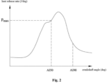
- the cylinder pressure can be ensured to be not less than the cylinder pressure upper threshold P max when the crankshaft angle has not reached the first angle after a limited number of movement cycles of the piston, thus the combustion speed and the air utilization rate in the cylinder in the middle and late combustion stages are improved.
- the first angle is AI50, so the method for controlling a combustion system can effectively shorten the time from AI50 to AI90, and control the combustion rate to be at P max stably during the period between AI50 and AI90.
- the specific value of P max may be set according to actual needs.
- the method for increasing the first injection pressure P 1 and/or wholly reducing the difference between the second time t 2 and the first time t 1 is as follows:
- the maximum value of the cylinder pressure P x during the first main fuel injection may be acquired from all values of the cylinder pressure collected during the movement cycle of the piston, and P max >P x .
- the increasing the first injection pressure P 1 by the first set value is taken as an example, and means that the first set value is added to the first injection pressure P 1 in the current movement cycle of reciprocating up and down of the piston, and the calculated value is used as a new first injection pressure P 1 , which is applied to the next movement cycle of the piston.
- the first injection pressure P 1 is increased by the first set value, and simultaneously the first time t 1 and/or the second time t 2 is adjusted to wholly reduce the difference between the second time t 2 and the first time t 1 by the second set value.
- the difference between P max and the maximum value P x of the cylinder pressure during the first main fuel injection is small when n ⁇ 5%.
- the injection rate of the oil beam may be directly improved by adjusting the first injection pressure P 1 , thereby the degree of oil-gas mixing and the flow field in the cylinder is improved, and the cylinder pressure P in the cylinder and the crankshaft angle when the cylinder pressure P reaches P max is adjusted.
- the difference between P max and the maximum value P x of the cylinder pressure during the first main fuel injection is relatively large when n>5%.
- the first set value and the second set value may be set as required, and only the second time t 2 or the first time t 1 may be adjusted separately as required when adjusting the difference between the second time t 2 and the first time t 1.
- a solution of adjusting the duration of the first main fuel injection and the first injection pressure based on experience is exemplarily provided.
- the duration of the first main fuel injection and the first injection pressure may also be adjusted by a model.
- step S20 if the cylinder pressure P is greater than or equal to the cylinder pressure upper threshold and the crankshaft angle is before the first angle, the method for controlling a combustion system further includes the following steps S40 to S80 after step S20.
- step S40 a real-time cylinder volume V in the cylinder is acquired when the cylinder pressure P is equal to the cylinder pressure upper threshold P max .
- acquiring the real-time cylinder volume in the cylinder is the conventional technology, for example, a cylinder pressure curve of each cycle of the diesel engine may be collected through a combustion analyzer, and thus the real-time cylinder volume in the cylinder is acquired.
- the real-time cylinder volume V is the cylinder volume V when the cylinder pressure reaches P max for the first time during the first main fuel injection.
- step S50 a crankshaft angle ⁇ a when the cylinder goes up and a crankshaft angle ⁇ b when the cylinder goes down when the cylinder volume is equal to the real-time cylinder volume V are acquired according to a relationship map between the cylinder volume and the crankshaft angle.
- the volume in the cylinder first decreases and then increases. Therefore, corresponding to a same real-time volume, there are a position of the crankshaft angle when the piston goes up and a position of the crankshaft angle when the piston goes down.
- the first cylinder pressure P corresponding to the crankshaft angle ⁇ a when the cylinder goes up is P 0
- the cylinder pressure P is equal to the cylinder pressure upper threshold P max when the crankshaft angle is ⁇ b when the cylinder goes down.
- the relationship map between the cylinder volume and the crankshaft angle may be acquired through a large number of previous experiments and is pre-stored in the controller.
- step S70 ⁇ 1 and the second preset rotation angle ⁇ n are compared.
- step S80 is executed.
- step S80 the first injection pressure P 1 is increased by a third set value, and/or the first time t 1 and/or the second time t 2 is adjusted to wholly reduce the difference between the second time t 2 and the first time t 1 by a fourth set value, and step S10 is repeated.
- a closed-loop adjustment of the angle that the crankshaft has rotated during the period when the cylinder pressure rises from the first cylinder pressure to the cylinder pressure upper threshold can be realized through steps S40 to S80, ensuring that ⁇ 1 is not less than ⁇ n after a limited number of movement cycles of the piston, and further ensuring the optimal economic efficiency of the entrainment superposition effects of the double main injections.
- ⁇ n , the third set value and the fourth set value may be set as required.
- the second injection pressure is P 2 .
- the step "iteratively adjusting at least one of the duration of the second main fuel injection and the second injection pressure, to allow the change rate of the curve slopes of the cylinder pressure change curve to be within the set range of slope change rates at each time point during the period when the cylinder pressure drops from the cylinder pressure upper threshold to the set cylinder pressure in the second main fuel injection, and to allow the angle that the crankshaft has rotated during the period when the cylinder pressure drops from the cylinder pressure upper threshold to the set cylinder pressure to be not less than the first preset rotation angle" in step S200 includes the following steps S90 to S140 after step S80.
- step S90 a crankshaft angle ⁇ c when the cylinder pressure P is equal to P n is acquired according to the map, ⁇ c > ⁇ b , P n is the set cylinder pressure and P max >P n .
- the cylinder pressure P corresponding to the crankshaft angle between ⁇ b and ⁇ c is at least not less than P n , the cylinder pressure can be considered to be within the peak fluctuation.
- P n may be set as required.
- step S100 a relationship curve y between the cylinder pressure and the crankshaft angle in a range from the crankshaft angle ⁇ b to the crankshaft angle ⁇ c is acquired.
- an independent variable is the crankshaft angle
- a dependent variable is the cylinder pressure.
- k 1 is a slope of the curve y
- k 2 is a change rate of the slope of the curve.
- step S120 a maximum value k max of an absolute value of k 2 is acquired.
- the maximum value of the absolute value of k 2 refers to a value of a largest absolute value of a smallest negative value of k 2 and a largest positive value of k 2 in the range of ⁇ from ⁇ b to ⁇ c .
- step S130 k max is compared with and a preset parameter k a .
- step S140 is executed.
- step S140 the second injection pressure P 2 is increased by a fifth set value, and step S10 is repeated.
- the specific value of k a and the fifth set value may be set as required.
- the value of k a is 0.05, and the corresponding set range of slope change rates is -0.05 to 0.05.
- the minimum value of k 2 is not less than k a , the value of k a is greater than or equal to 0.05. It can be understood that the injection rail pressure can be increased to maintain the cylinder pressure around a constant value by increasing the second injection pressure P 2 .
- a closed-loop adjustment of the change rate of curve slopes of the cylinder pressure change curve at any time point during the period when the cylinder pressure drops from the cylinder pressure upper threshold to the set cylinder pressure is realized through steps S90 to S140, which can ensure that the minimum value of k 2 is not less than k a after a limited number of movement cycles of the piston, and thus can ensure the optimal economic efficiency of the entrainment superposition effects of the double main injections.
- the timing when the injector ends the second main fuel injection is a third time t 3 . If k max ⁇ k a , the method for controlling a combustion system further includes the following steps S150 to S180 after step S130.
- step S160 ⁇ 2 and the first preset rotation angle ⁇ m are compared.
- Step S170 is executed in a case that ⁇ 2 ⁇ m
- step S180 is executed in a case that ⁇ 2 ⁇ m
- step S170 the third time t 3 is increased by a sixth set value.
- step S180 the third time t 3 is maintained constant.
- the sixth set value and the second preset rotation angle ⁇ m may be set as required.
- a closed-loop adjustment of the corresponding angle that the crankshaft has rotated during the period when the cylinder pressure drops from the cylinder pressure upper threshold to the set cylinder pressure is realized through steps S150 to S180, which can ensure that ⁇ 2 is not less than ⁇ m after a limited number of reciprocating movements of the piston, and further can ensure that the sum of ⁇ 1 and ⁇ 2 is large enough to optimize the economic efficiency of the entrainment superposition effects of the double main injections.
Landscapes
- Engineering & Computer Science (AREA)
- Chemical & Material Sciences (AREA)
- Combustion & Propulsion (AREA)
- Mechanical Engineering (AREA)
- General Engineering & Computer Science (AREA)
- Oil, Petroleum & Natural Gas (AREA)
- Electrical Control Of Air Or Fuel Supplied To Internal-Combustion Engine (AREA)
- Output Control And Ontrol Of Special Type Engine (AREA)
- Combined Controls Of Internal Combustion Engines (AREA)
Applications Claiming Priority (2)
| Application Number | Priority Date | Filing Date | Title |
|---|---|---|---|
| CN202110669915.1A CN113250843B (zh) | 2021-06-17 | 2021-06-17 | 一种燃烧系统的控制方法、燃烧系统及柴油机 |
| PCT/CN2022/073116 WO2022262276A1 (zh) | 2021-06-17 | 2022-01-21 | 一种燃烧系统的控制方法、燃烧系统及柴油机 |
Publications (2)
| Publication Number | Publication Date |
|---|---|
| EP4357603A1 true EP4357603A1 (de) | 2024-04-24 |
| EP4357603A4 EP4357603A4 (de) | 2025-06-25 |
Family
ID=77188303
Family Applications (1)
| Application Number | Title | Priority Date | Filing Date |
|---|---|---|---|
| EP22823771.5A Pending EP4357603A4 (de) | 2021-06-17 | 2022-01-21 | Steuerungsverfahren für verbrennungssystem, verbrennungssystem und dieselmotor |
Country Status (6)
| Country | Link |
|---|---|
| US (1) | US12180904B2 (de) |
| EP (1) | EP4357603A4 (de) |
| JP (1) | JP7684430B2 (de) |
| KR (1) | KR102821923B1 (de) |
| CN (1) | CN113250843B (de) |
| WO (1) | WO2022262276A1 (de) |
Families Citing this family (9)
| Publication number | Priority date | Publication date | Assignee | Title |
|---|---|---|---|---|
| CN113250843B (zh) | 2021-06-17 | 2021-09-17 | 潍柴动力股份有限公司 | 一种燃烧系统的控制方法、燃烧系统及柴油机 |
| CN114109637B (zh) * | 2022-01-28 | 2022-04-22 | 潍柴动力股份有限公司 | 一种柴油机的燃烧控制方法、装置和柴油机 |
| CN114251182B (zh) * | 2022-03-01 | 2022-06-21 | 潍柴动力股份有限公司 | 一种喷油器的控制方法、装置、柴油机及介质 |
| CN114320641B (zh) * | 2022-03-11 | 2022-06-21 | 潍柴动力股份有限公司 | 一种发动机燃烧系统、控制方法及发动机 |
| CN114720138A (zh) * | 2022-04-07 | 2022-07-08 | 潍柴动力股份有限公司 | 一种预喷开启角度的标定方法、装置、设备及存储介质 |
| CN115234391A (zh) * | 2022-06-22 | 2022-10-25 | 哈尔滨工程大学 | 氨内燃机定压燃烧控制方法及装置和内燃机 |
| CN118428185B (zh) * | 2024-04-28 | 2025-02-11 | 哈尔滨工程大学 | 一种高压直喷双燃料船用内燃机喷雾燃烧过程计算方法 |
| CN118148788B (zh) * | 2024-05-11 | 2024-08-16 | 潍柴动力股份有限公司 | 一种降低缸套温度的方法、装置、电子设备及存储介质 |
| CN118886076B (zh) * | 2024-09-27 | 2024-12-17 | 潍柴动力股份有限公司 | 燃烧系统的结构参数的确定方法、装置和系统 |
Family Cites Families (33)
| Publication number | Priority date | Publication date | Assignee | Title |
|---|---|---|---|---|
| FI864598A7 (fi) * | 1986-01-09 | 1987-07-10 | Sulzer Ag | Sprutsystem foer insprutning av braensle i en cylinder i en kolvfoerbraenningsmaskin. |
| IT1308412B1 (it) * | 1999-03-05 | 2001-12-17 | Fiat Ricerche | Metodo di controllo della combustione di un motore diesel ad iniezionediretta tramite l'attuazione di iniezioni multiple mediante un sistema |
| US6467452B1 (en) * | 2000-07-13 | 2002-10-22 | Caterpillar Inc | Method and apparatus for delivering multiple fuel injections to the cylinder of an internal combustion engine |
| US6378487B1 (en) * | 2000-09-01 | 2002-04-30 | International Truck And Engine Corporation | Method and apparatus for pre-pilot fuel injection in diesel internal combustion engines |
| US6935304B1 (en) * | 2004-03-17 | 2005-08-30 | International Engine Intellectual Property Company, Llc | Increasing the duration of peak combustion pressure in cylinders of a diesel engine using fuel injection control strategies |
| JP2006183466A (ja) | 2004-12-24 | 2006-07-13 | Nissan Motor Co Ltd | 内燃機関の燃焼制御装置 |
| JP2006274981A (ja) * | 2005-03-30 | 2006-10-12 | Mitsubishi Fuso Truck & Bus Corp | ディーゼル機関の制御装置 |
| JP2007247476A (ja) * | 2006-03-14 | 2007-09-27 | Honda Motor Co Ltd | 内燃機関の制御装置 |
| GB0621742D0 (en) * | 2006-10-31 | 2006-12-13 | Delphi Tech Inc | Fuel injection apparatus |
| DE102007024823B4 (de) * | 2007-05-29 | 2014-10-23 | Continental Automotive Gmbh | Verfahren und Vorrichtung zur Bestimmung eines Ansteuerparameters für einen Kraftstoffinjektor einer Brennkraftmaschine |
| JP4924751B1 (ja) * | 2010-11-09 | 2012-04-25 | マツダ株式会社 | 火花点火式直噴エンジンの制御方法及びその制御装置 |
| CN102135044B (zh) * | 2011-01-04 | 2013-08-14 | 潍柴动力股份有限公司 | 用于控制共轨系统喷油压力的方法、设备和系统 |
| JP5596730B2 (ja) * | 2011-07-01 | 2014-09-24 | 株式会社デンソー | 内燃機関の燃料噴射制御装置 |
| DE112012003727B4 (de) | 2011-09-07 | 2019-08-08 | Mazda Motor Corporation | Benzineinspritzmotor und Verfahren zur Kontrolle des Benzineinspritzmotors |
| JP5146581B1 (ja) | 2011-09-14 | 2013-02-20 | 株式会社豊田自動織機 | 燃焼制御装置 |
| JP5766654B2 (ja) | 2012-06-14 | 2015-08-19 | 株式会社デンソー | 燃料噴射制御装置および燃料噴射制御方法 |
| JP5873059B2 (ja) * | 2013-09-30 | 2016-03-01 | 株式会社豊田中央研究所 | 圧縮着火式内燃機関 |
| DE102015207252A1 (de) * | 2015-04-21 | 2016-10-27 | Avl List Gmbh | Verfahren und Vorrichtung zur modellbasierten Optimierung einer technischen Einrichtung |
| JP6477457B2 (ja) | 2015-11-13 | 2019-03-06 | 株式会社デンソー | 燃料噴射制御装置 |
| DE102016110112B9 (de) * | 2015-06-11 | 2021-04-01 | Denso Corporation | Kraftstoffeinspritzvorrichtung |
| JP6447434B2 (ja) * | 2015-09-15 | 2019-01-09 | 株式会社デンソー | 燃料噴射制御装置 |
| CN106812621B (zh) * | 2015-11-30 | 2019-11-22 | 长城汽车股份有限公司 | 一种发动机的喷油控制方法及系统 |
| DE102015121790A1 (de) * | 2015-12-15 | 2017-06-22 | Denso Corporation | Technologie zur Ausführung von hydraulisch gekoppelten Kraftstoff-Injektionen |
| US9903307B2 (en) * | 2016-01-04 | 2018-02-27 | Ford Global Technologies, Llc | Method of fuel injection control |
| DE102017217113A1 (de) * | 2017-09-26 | 2019-03-28 | Robert Bosch Gmbh | Verfahren zum Betreiben eines Verbrennungsmotors und elektronisches Steuergerät für einen Verbrennungsmotor |
| CN111712622B (zh) * | 2018-02-23 | 2022-09-13 | 瓦锡兰芬兰有限公司 | 操作活塞发动机的方法和活塞发动机 |
| CN108561233A (zh) * | 2018-03-14 | 2018-09-21 | 江苏科技大学 | 一种柴油/天然气双燃料发动机排放控制策略 |
| CN108533410A (zh) * | 2018-03-14 | 2018-09-14 | 天津大学 | 一种可燃用不同燃料的压燃式发动机及其控制方法 |
| JP7143757B2 (ja) | 2018-12-25 | 2022-09-29 | マツダ株式会社 | 圧縮着火式エンジンの制御装置 |
| JP7124732B2 (ja) * | 2019-01-29 | 2022-08-24 | マツダ株式会社 | 圧縮着火エンジンの制御装置 |
| JP7408962B2 (ja) * | 2019-09-10 | 2024-01-09 | マツダ株式会社 | ディーゼルエンジンの制御装置 |
| CN111188690B (zh) * | 2020-01-14 | 2022-08-05 | 潍柴动力股份有限公司 | 一种天然气发动机的燃烧控制方法及控制系统 |
| CN113250843B (zh) | 2021-06-17 | 2021-09-17 | 潍柴动力股份有限公司 | 一种燃烧系统的控制方法、燃烧系统及柴油机 |
-
2021
- 2021-06-17 CN CN202110669915.1A patent/CN113250843B/zh active Active
-
2022
- 2022-01-21 JP JP2023566498A patent/JP7684430B2/ja active Active
- 2022-01-21 US US18/290,406 patent/US12180904B2/en active Active
- 2022-01-21 EP EP22823771.5A patent/EP4357603A4/de active Pending
- 2022-01-21 KR KR1020237041890A patent/KR102821923B1/ko active Active
- 2022-01-21 WO PCT/CN2022/073116 patent/WO2022262276A1/zh not_active Ceased
Also Published As
| Publication number | Publication date |
|---|---|
| WO2022262276A1 (zh) | 2022-12-22 |
| JP2024515824A (ja) | 2024-04-10 |
| KR20240004974A (ko) | 2024-01-11 |
| US20240360798A1 (en) | 2024-10-31 |
| EP4357603A4 (de) | 2025-06-25 |
| KR102821923B1 (ko) | 2025-06-17 |
| CN113250843B (zh) | 2021-09-17 |
| CN113250843A (zh) | 2021-08-13 |
| JP7684430B2 (ja) | 2025-05-27 |
| US12180904B2 (en) | 2024-12-31 |
Similar Documents
| Publication | Publication Date | Title |
|---|---|---|
| EP4357603A1 (de) | Steuerungsverfahren für verbrennungssystem, verbrennungssystem und dieselmotor | |
| US9506439B2 (en) | Ducted combustion systems utilizing adjustable length ducts | |
| KR100780122B1 (ko) | 디젤 엔진 및 예비 혼합 압축착화 연소의 제어 방법 | |
| US12134995B2 (en) | Method for controlling combustion system, combustion system, and internal combustion engine | |
| EP4357594A1 (de) | Steuerungsverfahren für verbrennungssystem, verbrennungssystem und motor | |
| US20160053667A1 (en) | Prechamber assembly for an engine | |
| WO2009067495A2 (en) | Premix combustion methods, devices and engines using the same | |
| GB2385377A (en) | Low pressure direct injection engine system | |
| US5911207A (en) | Fuel injection pump | |
| EP3460223A1 (de) | Verbrennungsmotorsteuerungsvorrichtung | |
| RU2824657C2 (ru) | Способ управления для системы сгорания, система сгорания и дизельный двигатель | |
| US11959435B1 (en) | Turbulent jet controlled compression ignition (TJCCI) engine | |
| CN100363606C (zh) | 一种在直喷汽油机上实现燃烧模式切换的燃烧控制方法 | |
| WO2011008706A2 (en) | Adaptive mixed-mode combustion methods and engines using the same | |
| KR20210033793A (ko) | 실린더 물 분사 다중화 방법 및 물 분사 시스템 | |
| WO2023165273A1 (zh) | 喷油装置及喷油装置的参数标定方法 | |
| RU2833451C2 (ru) | Способ управления для системы сгорания, система сгорания и двигатель | |
| CN115234360B (zh) | 用于斜轴涡流增强的燃烧室、发动机及点火控制方法 | |
| CN121322211A (zh) | 一种中大缸径甲醇发动机的燃烧系统、工作方法和发动机 | |
| CN117469024A (zh) | 一种适用于对置活塞发动机的强制破碎燃烧系统 | |
| CN113374608A (zh) | 一种燃料空气集成喷射器及包含其的点火室系统 | |
| CN119021802A (zh) | 一种适用于对置二冲程小缸径活塞的内冷油腔异型结构 | |
| CN120291963A (zh) | 一种氢内燃机射流引燃系统及氢内燃机控制方法 | |
| JPH05288097A (ja) | 筒内噴射式内燃機関 | |
| CN108167101A (zh) | 一种柴油内燃机的油气混合质量优化方法 |
Legal Events
| Date | Code | Title | Description |
|---|---|---|---|
| STAA | Information on the status of an ep patent application or granted ep patent |
Free format text: STATUS: THE INTERNATIONAL PUBLICATION HAS BEEN MADE |
|
| PUAI | Public reference made under article 153(3) epc to a published international application that has entered the european phase |
Free format text: ORIGINAL CODE: 0009012 |
|
| STAA | Information on the status of an ep patent application or granted ep patent |
Free format text: STATUS: REQUEST FOR EXAMINATION WAS MADE |
|
| 17P | Request for examination filed |
Effective date: 20231024 |
|
| AK | Designated contracting states |
Kind code of ref document: A1 Designated state(s): AL AT BE BG CH CY CZ DE DK EE ES FI FR GB GR HR HU IE IS IT LI LT LU LV MC MK MT NL NO PL PT RO RS SE SI SK SM TR |
|
| DAV | Request for validation of the european patent (deleted) | ||
| DAX | Request for extension of the european patent (deleted) | ||
| A4 | Supplementary search report drawn up and despatched |
Effective date: 20250528 |
|
| RIC1 | Information provided on ipc code assigned before grant |
Ipc: F02D 35/02 20060101ALI20250522BHEP Ipc: F02M 45/12 20060101ALI20250522BHEP Ipc: F02D 41/14 20060101ALI20250522BHEP Ipc: F02D 41/38 20060101ALI20250522BHEP Ipc: F02D 41/40 20060101AFI20250522BHEP |