EP4357632A1 - Unité de palier - Google Patents
Unité de palier Download PDFInfo
- Publication number
- EP4357632A1 EP4357632A1 EP23202616.1A EP23202616A EP4357632A1 EP 4357632 A1 EP4357632 A1 EP 4357632A1 EP 23202616 A EP23202616 A EP 23202616A EP 4357632 A1 EP4357632 A1 EP 4357632A1
- Authority
- EP
- European Patent Office
- Prior art keywords
- component
- ring
- adapter ring
- bearing
- outer ring
- Prior art date
- Legal status (The legal status is an assumption and is not a legal conclusion. Google has not performed a legal analysis and makes no representation as to the accuracy of the status listed.)
- Granted
Links
Images



Classifications
-
- H—ELECTRICITY
- H02—GENERATION; CONVERSION OR DISTRIBUTION OF ELECTRIC POWER
- H02K—DYNAMO-ELECTRIC MACHINES
- H02K5/00—Casings; Enclosures; Supports
- H02K5/04—Casings or enclosures characterised by the shape, form or construction thereof
- H02K5/16—Means for supporting bearings, e.g. insulating supports or means for fitting bearings in the bearing-shields
- H02K5/173—Means for supporting bearings, e.g. insulating supports or means for fitting bearings in the bearing-shields using bearings with rolling contact, e.g. ball bearings
- H02K5/1732—Means for supporting bearings, e.g. insulating supports or means for fitting bearings in the bearing-shields using bearings with rolling contact, e.g. ball bearings radially supporting the rotary shaft at both ends of the rotor
-
- F—MECHANICAL ENGINEERING; LIGHTING; HEATING; WEAPONS; BLASTING
- F16—ENGINEERING ELEMENTS AND UNITS; GENERAL MEASURES FOR PRODUCING AND MAINTAINING EFFECTIVE FUNCTIONING OF MACHINES OR INSTALLATIONS; THERMAL INSULATION IN GENERAL
- F16C—SHAFTS; FLEXIBLE SHAFTS; ELEMENTS OR CRANKSHAFT MECHANISMS; ROTARY BODIES OTHER THAN GEARING ELEMENTS; BEARINGS
- F16C35/00—Rigid support of bearing units; Housings, e.g. caps, covers
- F16C35/04—Rigid support of bearing units; Housings, e.g. caps, covers in the case of ball or roller bearings
- F16C35/06—Mounting or dismounting of ball or roller bearings; Fixing them onto shaft or in housing
- F16C35/067—Fixing them in a housing
-
- F—MECHANICAL ENGINEERING; LIGHTING; HEATING; WEAPONS; BLASTING
- F16—ENGINEERING ELEMENTS AND UNITS; GENERAL MEASURES FOR PRODUCING AND MAINTAINING EFFECTIVE FUNCTIONING OF MACHINES OR INSTALLATIONS; THERMAL INSULATION IN GENERAL
- F16C—SHAFTS; FLEXIBLE SHAFTS; ELEMENTS OR CRANKSHAFT MECHANISMS; ROTARY BODIES OTHER THAN GEARING ELEMENTS; BEARINGS
- F16C35/00—Rigid support of bearing units; Housings, e.g. caps, covers
- F16C35/04—Rigid support of bearing units; Housings, e.g. caps, covers in the case of ball or roller bearings
- F16C35/06—Mounting or dismounting of ball or roller bearings; Fixing them onto shaft or in housing
- F16C35/07—Fixing them on the shaft or housing with interposition of an element
- F16C35/077—Fixing them on the shaft or housing with interposition of an element between housing and outer race ring
-
- H—ELECTRICITY
- H02—GENERATION; CONVERSION OR DISTRIBUTION OF ELECTRIC POWER
- H02K—DYNAMO-ELECTRIC MACHINES
- H02K5/00—Casings; Enclosures; Supports
- H02K5/04—Casings or enclosures characterised by the shape, form or construction thereof
- H02K5/10—Casings or enclosures characterised by the shape, form or construction thereof with arrangements for protection from ingress, e.g. water or fingers
-
- F—MECHANICAL ENGINEERING; LIGHTING; HEATING; WEAPONS; BLASTING
- F16—ENGINEERING ELEMENTS AND UNITS; GENERAL MEASURES FOR PRODUCING AND MAINTAINING EFFECTIVE FUNCTIONING OF MACHINES OR INSTALLATIONS; THERMAL INSULATION IN GENERAL
- F16C—SHAFTS; FLEXIBLE SHAFTS; ELEMENTS OR CRANKSHAFT MECHANISMS; ROTARY BODIES OTHER THAN GEARING ELEMENTS; BEARINGS
- F16C19/00—Bearings with rolling contact, for exclusively rotary movement
- F16C19/02—Bearings with rolling contact, for exclusively rotary movement with bearing balls essentially of the same size in one or more circular rows
- F16C19/04—Bearings with rolling contact, for exclusively rotary movement with bearing balls essentially of the same size in one or more circular rows for radial load mainly
- F16C19/06—Bearings with rolling contact, for exclusively rotary movement with bearing balls essentially of the same size in one or more circular rows for radial load mainly with a single row or balls
-
- F—MECHANICAL ENGINEERING; LIGHTING; HEATING; WEAPONS; BLASTING
- F16—ENGINEERING ELEMENTS AND UNITS; GENERAL MEASURES FOR PRODUCING AND MAINTAINING EFFECTIVE FUNCTIONING OF MACHINES OR INSTALLATIONS; THERMAL INSULATION IN GENERAL
- F16C—SHAFTS; FLEXIBLE SHAFTS; ELEMENTS OR CRANKSHAFT MECHANISMS; ROTARY BODIES OTHER THAN GEARING ELEMENTS; BEARINGS
- F16C2226/00—Joining parts; Fastening; Assembling or mounting parts
- F16C2226/50—Positive connections
- F16C2226/62—Positive connections with pins, bolts or dowels
-
- F—MECHANICAL ENGINEERING; LIGHTING; HEATING; WEAPONS; BLASTING
- F16—ENGINEERING ELEMENTS AND UNITS; GENERAL MEASURES FOR PRODUCING AND MAINTAINING EFFECTIVE FUNCTIONING OF MACHINES OR INSTALLATIONS; THERMAL INSULATION IN GENERAL
- F16C—SHAFTS; FLEXIBLE SHAFTS; ELEMENTS OR CRANKSHAFT MECHANISMS; ROTARY BODIES OTHER THAN GEARING ELEMENTS; BEARINGS
- F16C2226/00—Joining parts; Fastening; Assembling or mounting parts
- F16C2226/50—Positive connections
- F16C2226/70—Positive connections with complementary interlocking parts
- F16C2226/76—Positive connections with complementary interlocking parts with tongue and groove or key and slot
-
- F—MECHANICAL ENGINEERING; LIGHTING; HEATING; WEAPONS; BLASTING
- F16—ENGINEERING ELEMENTS AND UNITS; GENERAL MEASURES FOR PRODUCING AND MAINTAINING EFFECTIVE FUNCTIONING OF MACHINES OR INSTALLATIONS; THERMAL INSULATION IN GENERAL
- F16C—SHAFTS; FLEXIBLE SHAFTS; ELEMENTS OR CRANKSHAFT MECHANISMS; ROTARY BODIES OTHER THAN GEARING ELEMENTS; BEARINGS
- F16C23/00—Bearings for exclusively rotary movement adjustable for aligning or positioning
- F16C23/06—Ball or roller bearings
- F16C23/08—Ball or roller bearings self-adjusting
-
- F—MECHANICAL ENGINEERING; LIGHTING; HEATING; WEAPONS; BLASTING
- F16—ENGINEERING ELEMENTS AND UNITS; GENERAL MEASURES FOR PRODUCING AND MAINTAINING EFFECTIVE FUNCTIONING OF MACHINES OR INSTALLATIONS; THERMAL INSULATION IN GENERAL
- F16C—SHAFTS; FLEXIBLE SHAFTS; ELEMENTS OR CRANKSHAFT MECHANISMS; ROTARY BODIES OTHER THAN GEARING ELEMENTS; BEARINGS
- F16C2380/00—Electrical apparatus
- F16C2380/26—Dynamo-electric machines or combinations therewith, e.g. electro-motors and generators
-
- F—MECHANICAL ENGINEERING; LIGHTING; HEATING; WEAPONS; BLASTING
- F16—ENGINEERING ELEMENTS AND UNITS; GENERAL MEASURES FOR PRODUCING AND MAINTAINING EFFECTIVE FUNCTIONING OF MACHINES OR INSTALLATIONS; THERMAL INSULATION IN GENERAL
- F16C—SHAFTS; FLEXIBLE SHAFTS; ELEMENTS OR CRANKSHAFT MECHANISMS; ROTARY BODIES OTHER THAN GEARING ELEMENTS; BEARINGS
- F16C35/00—Rigid support of bearing units; Housings, e.g. caps, covers
- F16C35/04—Rigid support of bearing units; Housings, e.g. caps, covers in the case of ball or roller bearings
- F16C35/06—Mounting or dismounting of ball or roller bearings; Fixing them onto shaft or in housing
- F16C35/063—Fixing them on the shaft
Definitions
- the invention relates to a bearing unit with a rolling bearing.
- the invention also relates to a method for producing a structural unit with a bearing unit and an electric motor.
- Electric motors usually have a substantially hollow cylindrical housing, which is closed at its end faces by means of a bearing plate, one of which is the so-called A-side bearing plate, which is located on the side of the electric motor on which a component connected to it is driven.
- the opposite bearing plate is called the B-side bearing plate.
- the bearing plates themselves are attached to the housing.
- a rolling bearing is usually arranged on each bearing plate, by means of which a shaft of the electric motor guided through the housing is rotatably mounted.
- the rolling bearing On the B-side bearing shield, the rolling bearing is rigidly attached to the bearing shield. In other words, this rolling bearing is a fixed bearing. Since the thermal properties of the individual components of the electric motor are different, it is possible that the shaft expands to a different extent as the temperature increases than the housing, which determines the distance between the bearing shields. To prevent mechanical stresses from developing in the shaft between the two bearing shields, the bearing assigned to the other bearing shield, namely the A-side bearing shield, is mounted on it so that it can move axially, i.e. along the direction of expansion of the shaft. In other words, this is a floating bearing.
- the rolling bearing is usually attached to the bearing plate not by means of a positive connection, but by means of a frictional connection.
- the frictional connection is such that when forces occur in the axial direction, which would otherwise lead to the formation of mechanical stresses, the rolling bearing is displaced on the bearing plate.
- the rolling bearing is surrounded on the outside by an O-ring made of an elastic material such as plastic or rubber.
- the rolling bearing is inserted into a pot-shaped or hollow-cylindrical holder in the bearing plate, with the mechanical contact between the bearing plate and the rolling bearing being made solely or at least partly via the O-ring.
- the invention is based on the object of specifying a particularly suitable bearing unit and a particularly suitable method for producing a structural unit as well as a particularly suitable electric motor, wherein in particular durability is increased and wherein manufacturing costs are expediently reduced.
- the bearing unit has a rolling bearing and a first and a second component.
- One of the components or both components are, for example, composed of several individual components or, expediently, are in one piece.
- at least one of the two components is made of a metal, such as aluminum, i.e. pure aluminum or an aluminum alloy, or steel.
- the first component is mounted so as to be rotatable about an axis with respect to the second component.
- the first component is a hub and the second component is a fixed axis.
- the first component is particularly preferably a shaft, which is made, for example, of steel, such as hardened steel.
- the second component is, for example, a component of a housing or preferably a bearing plate or a component of the bearing plate.
- the bearing unit is a component of an electric motor or a gear.
- the bearing unit is expediently a component of an industrial plant or at least of a tool.
- the bearing unit is a component of an injection molding machine, such as an electric motor of the injection molding machine.
- a power of between 18 kW and 150 kW is transmitted by means of the bearing unit during operation.
- the rolling bearing has an outer ring and an inner ring that can rotate about the axis.
- the inner ring is expediently surrounded on the outside by the outer ring, and the outer ring and the inner ring are preferably arranged concentrically to the axis.
- the inner ring and the outer ring are preferably designed to be rotationally symmetrical with respect to the axis, so that imbalance is avoided.
- several rolling elements such as cylinders or balls, are arranged between the inner ring and the outer ring, via which the inner ring and the outer ring rest against one another.
- the inner ring and the outer ring are made of the same material, for example steel.
- the rolling elements are preferably made of a relatively robust material, such as steel.
- the inner ring is attached to the first component.
- the first component is immobile with respect to the inner ring, and the inner ring is connected to the first component in a rotationally fixed manner, so that rotation of the two relative to one another is prevented. Axial movement of the inner ring with respect to the first component is also prevented.
- the first component at least in the region of the inner ring, is radially surrounded by the inner ring, in particular with respect to the axis.
- the inner ring and the first component lie directly against one another mechanically.
- the inner ring is attached to the first component by means of an adhesive or by means of fastening means, such as screws.
- the inner ring is shrunk onto the first component.
- the first component is rotationally symmetrical with respect to the axis, so that imbalance is avoided.
- the adapter ring is attached to the outer ring.
- the adapter ring is therefore also neither rotatable with respect to the outer ring, nor is it possible to move the outer ring with respect to the adapter ring in a longitudinal direction, such as axially, so that they form a structural unit. In other words, a relative movement of the adapter ring with respect to the outer ring is not possible or at least not desired.
- the adapter ring is arranged concentrically to the axis.
- the outer ring itself is mounted on the second component in a rotationally secure and axially movable manner.
- the adapter ring is mounted on the second component in a rotationally secure manner. mounted so that, due to the anti-twisting device, a rotational movement of the adapter ring and thus also of the outer ring with respect to the second component around the axis is prevented.
- the adapter ring Due to the use of the adapter ring, it is possible to use a standard component for the rolling bearing. In other words, there are no special specifications for the rolling bearing. This reduces the manufacturing costs of the rolling bearing on the one hand. On the other hand, availability is increased due to the possibility of using standard components. In other words, the delivery time for the rolling bearing is reduced, so that the bearing unit can be manufactured essentially without further restrictions. Only the adapter ring has to be manufactured accordingly, although there are comparatively few requirements for this compared to the rolling bearing.
- the second component has in particular a recess within which the rolling bearing is at least partially arranged, in particular the inner ring.
- the first component protrudes through the recess, and the first component is at least partially surrounded circumferentially by means of the second component.
- the adapter ring surrounds the outer ring circumferentially.
- the adapter ring is offset outwardly from the outer ring with respect to the axis.
- the adapter ring is made, for example, from several different components that are put together, for example by means of gluing or one or more fastening elements, such as screws.
- the components are joined together.
- the outer ring is particularly preferably made in one piece, which increases robustness.
- one or more fastening means, such as screws are used to fasten the adapter ring to the outer ring.
- the adapter ring is designed in the manner of a clamp that is tightened around the outer ring, with a corresponding fastening means being expediently used.
- the adapter ring is fastened to the outer ring using an adhesive.
- the adapter ring is particularly preferably shrunk onto the outer ring.
- the adapter ring is heated to a comparatively high temperature, for example, so that it expands.
- the adapter ring is then suitably positioned in relation to the outer ring and cooled so that its expansion is reduced and a force-fit connection is created between them.
- the inner diameter of the adapter ring is slightly smaller than the outer diameter of the outer ring before assembly.
- the adapter ring surrounds the outer ring only on the circumference.
- the outer ring is gripped by the adapter ring.
- the adapter ring is thus axially aligned with the outer ring, i.e. in a direction parallel to the axis, at least partially over, preferably only on one side.
- the overhang is also designed such that it rests on the front side of the outer ring.
- the cross-section of the adapter ring along the axis is at least partially L-shaped. As a result, a stop is formed here, by means of which the position of the adapter ring with respect to the outer ring is predetermined. This simplifies assembly.
- the adapter ring is stabilized by means of the radially inwardly offset part of the adapter ring, so that robustness is increased.
- the overhang, and thus the wraparound, is only on one side, so that the outer ring can be inserted into the adapter ring from the end opposite the stop.
- the second component has several projections or the like that engage in corresponding recesses of the adapter ring, each of which is arranged parallel to the axis.
- the anti-twisting device and/or the axial bearing are at least partially implemented by means of this.
- the adapter ring particularly preferably has several extensions that run parallel to the axis. The extensions are spaced from the axis and in particular are offset radially outwards from the outer ring with respect to the axes. Each of the extensions is guided in a corresponding receptacle of the second component. In particular, a clearance fit is formed between each extension and the respective receptacle, so that the extensions can be moved in the receptacles.
- each extension in the respectively assigned receptacle it is possible to move each extension in the respectively assigned receptacle between 0.5 mm and 5 mm.
- the mobility of the extensions in the respective receptacle is preferably limited to less than 2 mm or, for example, to 1 mm.
- each of the receptacles has a depth that is in particular 1 mm deeper than the length of the respective extension.
- the extensions and the receptacles are used to axially move the adapter ring on the second component, whereby the anti-twisting protection is achieved due to the clearance between the receptacles and the extensions.
- This enables a comparatively cost-effective connection of the adapter ring to the second component. It is possible to use an existing second component into which corresponding receptacles are made. This means that an existing construction can be used for the second component and it is not necessary to produce corresponding molds or tools for the second component. This reduces manufacturing costs for the second component.
- the second component is upgraded to ensure that the adapter ring can be mounted on it in a rotationally secure and axially movable manner by removing material.
- the receptacles are designed to be closed on the circumference or preferably slotted parallel to the axis on at least one side. This allows air to escape from the receptacles and prevents the formation of an air cushion in the receptacles, which could otherwise lead to a restriction of axial mobility.
- the extension and receptacles are arranged rotationally symmetrically with respect to the axis, so that an angle of 120° with respect to the axis is formed between them. This increases stability.
- the adapter ring suitably has a circumferential bead pointing radially away from the outer ring.
- the bead does not extend along the full extent of the adapter ring in the axial direction, but is shortened in comparison.
- the bead is assigned to one of the ends of the adapter ring in the axial direction (axial direction) and in particular forms this.
- the extensions are attached to the bead. If by means of the Since the outer ring is encompassed by the adapter ring, the bead is preferably arranged opposite the radially inward projection, so that the cross section of the adapter ring in the axial direction is at least partially essentially T-shaped. Due to the bead, the attachment of the adapter ring to the outer ring is not impaired by means of the extensions, so that stability is increased.
- the extensions are initially separate components that are attached to the bead.
- the bead has corresponding holes or bores into which the extensions are inserted, which are designed like pins, for example.
- the extensions are screwed or pressed into the holes.
- the extensions are glued to the bead.
- the extensions are designed in the manner of a nose and are molded onto the bead and other components of the adapter ring.
- the extensions are molded onto the other components of the adapter ring or at least the bead. Due to the one-piece design, robustness is increased and, in particular, production time is shortened.
- the bead is used to stabilize the extensions, which are also conveniently attached to other components of the outer ring, so that robustness is increased.
- the adapter ring particularly preferably has a threaded hole which expediently runs parallel to the axis of rotation.
- the threaded hole has an internal thread.
- the threaded hole is made in the possibly existing bead so that it is offset from the axis with respect to the outer ring.
- the threaded hole is arranged in particular congruent with a hole in the second component which also runs parallel to the axis.
- the diameter of the hole corresponds at least to the diameter of the threaded hole or is larger. It is thus possible to insert a threaded rod into the threaded hole of the adapter ring through the second component.
- the hole is designed to be smooth on the inside so that the hole does not hinder the movement of the threaded rod.
- the threaded rod is used to specify the position of the adapter ring in relation to the hole and thus in relation to the second component, and the adapter ring can therefore only be mounted on the second component in a predetermined position.
- the adapter ring in particular engages in corresponding contours of the second component, in particular the extensions engage in the corresponding receptacles, so that the adapter ring is mounted axially movably on the second component.
- the threaded rod is used to partially mount the adapter ring in an axially displaceable and twist-proof manner with respect to the second component.
- the method is used to produce a structural unit that has a bearing unit.
- the bearing unit comprises a rolling bearing that has an outer ring and an inner ring that can rotate about an axis.
- the inner ring is attached to a first component and the outer ring is attached to an adapter ring.
- the adapter ring is mounted on a second component in a rotationally secure and axially movable manner.
- the adapter ring has a threaded hole that, in the assembled state, is arranged congruently with a hole in the second component.
- the structural unit is, for example, an electric motor, a part of an electric motor or, for example, a gearbox or a part of a gearbox.
- the method provides that the first component is provided to which the rolling bearing is attached.
- the first component is a shaft, which is made of steel, for example.
- the inner ring of the rolling bearing is shrunk onto the first component, for example the shaft.
- the adapter ring is already attached to the outer ring.
- the adapter ring is not yet mounted on the second component, and this is in particular separate from the adapter ring.
- a threaded rod is screwed into the threaded hole.
- this step takes place before the adapter ring is attached to the outer ring and/or before the rolling bearing is attached to the first component.
- the threaded rod is only screwed into the threaded hole after the rolling bearing has been attached to the first component and the adapter ring has been attached to the outer ring, so that the attachment of the individual components to one another is not hindered by the presence of the threaded rod.
- the threaded rod is screwed completely into the threaded hole or, expediently, only to the extent that the threaded rod no longer detaches itself from the threaded hole. This reduces the amount of work involved.
- the threaded rod is then guided through the hole in the second component.
- the first component is also moved through a recess in the second component, within which the inner ring is expediently also arranged at least partially in the assembled state.
- the adapter ring is aligned with respect to the second component and arranged in such a way that it is mounted on the second component in a rotationally secure and axially movable manner. Because the outer ring can be rotated with respect to the inner ring, essentially no effort is required for alignment.
- the adapter ring is aligned using the threaded rod in such a way that, for example, any extensions engage in the corresponding receptacles or at least the adapter ring is mounted accordingly on the second component.
- the adapter ring is locked to the second component for this purpose.
- the second component is attached to another component, such as a housing or a part of a housing.
- the second component is screwed or welded to the other component.
- an axial Movability of the adapter ring with respect to the second component is attached to the second component.
- the threaded rod is removed from the threaded bore and the hole.
- the hole is expediently closed after the threaded rod has been removed.
- the invention also relates to such a structural unit, which is, for example, a gear, a component of a gear, an electric motor or a component of an electric motor.
- the electric motor is, for example, a component of an industrial plant, preferably an actuator, which is suitable for producing and/or processing a workpiece, in particular intended and set up.
- the electric motor is a component of an injection molding machine and in particular has an output greater than 10 kW or 20 kW.
- the output of the electric motor is less than 200 kW.
- the electric motor has a bearing unit with a rolling bearing, which comprises an outer ring and an inner ring that can rotate about an axis.
- the inner ring is attached to a first component and the outer ring to an adapter ring.
- the adapter ring is mounted on a second component in a rotationally secure and axially movable manner.
- the first component is formed by a shaft and the second component by a bearing plate of the electric motor.
- the bearing plate is an A-side bearing plate, and a floating bearing is formed in particular by means of the bearing unit.
- the shaft is supported by means of a further bearing, wherein this bearing is expediently designed as a fixed bearing that is fastened to the B-side bearing plate.
- the electric motor comprises a housing that is in particular designed as a hollow cylinder and that extends between the two bearing plates.
- the housing forms a further component to which the B-side bearing plate, preferably also the A-side bearing plate, is fastened.
- the electric motor thus forms a structural unit, wherein expediently the A-side bearing plate has a hole that is arranged congruently with a threaded hole in the adapter ring.
- the electric motor can be manufactured according to the method.
- the housing with the B-side bearing shield already attached to it, with the shaft with any rotor already inserted into the housing.
- the A-side bearing shield is used to close the housing, with assembly taking place using the threaded rod. This enables the bearing unit to be aligned accordingly from outside the housing, and the housing can thus be designed to be comparatively stable.
- the hole is closed, for example using a plug. This prevents foreign particles from entering the housing of the electric motor.
- an electric motor 4 is shown in perspective.
- the electric motor 4 has an output of 100 kW and, when assembled, is a component of an injection molding machine.
- the electric motor 4 comprises a structural unit 6 with a further component 8, namely a hollow-cylindrical housing that is arranged along the axis 2, with the axis 2 extending essentially centrally through the housing.
- a stator 10 is arranged within the housing, i.e. the further component 8, and is protected by the further component 8.
- a second component 12 of the assembly 6 is attached to the further component 8, namely an A-side bearing plate.
- the second component 12 is made of aluminum, just like the further component 8.
- the second component 12 is part of a bearing unit 14, which also has a first component 16, namely a shaft, which is arranged concentrically to the axis 2 and extends along it.
- the first component 16 is made of unhardened steel and is guided through a recess 18 in the second component 12.
- a rolling bearing 20 is also partially arranged within the recess 18, which has an inner ring 22 that is rotatable with respect to an outer ring 24 of the rolling bearing 20.
- the inner ring 22 and the outer ring 24 are arranged concentrically to the axis 2, and the outer ring 24 surrounds the inner ring 22 on the circumference.
- Rolling elements (not shown in detail) are arranged between these, namely in this example several balls (not shown) by means of which the mechanical contact between the inner ring 22 and the outer ring 24 takes place.
- the rolling elements are held due to a partial positive connection between the inner ring 22 and the outer ring 24, so that an axial movement of these to each other, i.e. parallel to axis 2, is not possible. It is possible to use a standard component for the rolling bearing 20.
- the inner ring 22 is attached to the first component 16, namely the shaft, for example by means of shrinking. This prevents movement of the inner ring 22 with respect to the first component 16, in particular along the axis, and also rotation of the inner ring 22 about the axis 2.
- the outer ring 24 is surrounded on the circumference by an adapter ring 26, which is shown in perspective in Figure 2 from the side of the rolling bearing 20.
- the adapter ring 26 is made of steel or aluminum and has a hollow cylindrical body 28 which, in the assembled state, surrounds the outer ring 24 on the circumference and rests against it.
- the extension of the adapter ring 26 in the axial direction, i.e. parallel to the axis 2, is less than the extension of the outer ring 24.
- An overhang 30 is formed on the body 28, i.e. a projection which is bent or offset towards the axis 2.
- the overhang 30 is disk-like and arranged concentrically to the axis 2, so that the overhang 30 forms a stop for the outer ring 24, against which it rests on the front side.
- the outer ring 24 is consequently gripped by means of the adapter ring 26.
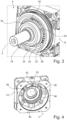
- the adapter ring 26 is attached to the outer ring 24 so that a relative movement of these to each other is not possible, as in Figure 3 shown in perspective, with the second component 12, namely the bearing plate of the electric motor 4, not shown.
- the adapter ring 26 is shrunk onto the outer ring 24.
- the outer ring 26 is first heated so that its diameter expands, namely in particular the diameter of the body 28.
- the rolling bearing 20 and thus the outer ring 24 are inserted into the body 28 from the side facing away from the overlap 30 in the axial direction until the outer ring 24 rests against the overlap 30.
- the adapter ring 26 is then cooled again so that it contracts again and rests against the outer ring 24 in a force-fitting manner.
- no structural weakening of the rolling bearing 20 occurs during fastening.
- the adapter ring 26 Opposite the overlap 30, namely offset radially outwards, there is a bead 32 of the adapter ring 26, which is also designed in the shape of a disk.
- the bead 32 points radially away from the axis 2 and thus also away from the outer ring 24, and the bead 32 is designed to run all the way around.
- the cross section of the adapter ring 26 along the axis 2 is thus partially T-shaped.
- the adapter ring 26 has a total of three extensions 34 which are designed like noses and which extend parallel to the axis 2.
- Each of the essentially cuboid-shaped extensions 34 is flush with the end of the bead 32 in the radial direction with respect to the axis 2 and flush with one of the ends of the body 28 in the axial direction.
- the extensions 34 are molded onto the body 28 and the bead 32, and the complete outer ring 26 is in one piece.
- the second component 12 namely the bearing plate, has three receptacles 36 running parallel to the axis 2, as shown in Figure 4 shown in perspective from the side of the further component 8.
- the receptacles 39 are in a hollow cylindrical collar 38 of the second component 12, which surrounds the recess 18.
- the receptacles 36 are essentially formed by means of slots in the collar 38 that run parallel to the axis 2. In the assembled state, one of the extensions 34 lies in one of the collars 36, with a clearance fit being formed between them.
- each receptacle 36 in the axial direction is 1 mm greater than the extent of the respectively assigned extension 34, so that a movement of the adapter ring 26 with respect to the collar 38 and thus also with respect to the second component 12 is possible to a small extent.
- each extension 34 is assigned to one of the receptacles 36 and is guided by means of this.
- the adapter ring 26 is mounted on the second component 12 in an axially movable manner, whereby the extent of the mobility is limited to 1 mm due to the design of the receptacles 36 and the extensions 34 and the bead 32 and the collar 38. Due to the clearance between the extensions 34 and the receptacles 36, a rotational movement of the adapter ring 26 with respect to the second component 12 is not possible.
- the adapter ring 26 is mounted on the second component 12 in a rotationally secure and axially movable manner. Therefore, the outer ring 24 of the rolling bearing 20 is also mounted accordingly on the second component 12. In other words, the rolling bearing 20 forms a floating bearing of the electric motor 4.
- the first component 16 is rotatably mounted on the second component 12 by means of the rolling bearing 20.
- the bearing plate, i.e. the second component 12 is an A-side bearing plate, which is why a component to be driven is arranged on this side of the electric motor 4 in the assembled state.
- the extensions 34 and consequently also the receptacles 36 are offset from one another by 120° with respect to the axis 2.
- a threaded hole 40 with an internal thread is made in the bead 32 centrally between two of the extensions 34. In the assembled state, this is arranged so that it is congruent with a hole 42 of the second component 12 that runs parallel to the axis 2.
- the diameter of the hole 42 is larger than the diameter of the threaded hole 40, so that the projection of the hole 42 onto the bead 32 completely covers the threaded hole 40. Consequently, the hole 42 is located between two of the receptacles 36 and forms an angle of 60° with them with respect to the axis 2.
- a plug 44 made of rubber is made in the hole 42 from the outside, i.e. from the end opposite the adapter ring 26. This prevents foreign particles from entering the interior of the electric motor 4 via the hole 42.
- a method 46 for producing the assembly 6 is shown.
- the first component 16 is provided, as in Figure 3 shown.
- the rolling bearing 20 is already attached to the first component 16, for example by means of shrinking, and the adapter ring 26 is already attached to the outer ring 24, i.e. to the rolling bearing 20, for example also by means of shrinking.
- the first component 16 and a rotor attached thereto are arranged within the further component 8 and the stator 10 attached thereto, and the opposite end of the housing formed by the further component 8 is closed by means of an A-side bearing shield.
- the first component 16, i.e. the shaft is attached to the A-side by means of a
- the bearing is mounted on a bearing shield and can rotate about axis 2, whereby this bearing is a fixed bearing.
- a threaded rod is screwed into the threaded bore 40 from the side facing away from the further component 8, which is arranged parallel to the axis 2.
- the threaded rod extends, for example, to the end of the shaft, i.e. the first component 16, in the axial direction.
- the second component 12 is placed on the first component 16 and the threaded rod.
- the first component 16 as the shaft, is guided through the recess 18, and the threaded rod, which is detachably attached to the adapter ring 26, is guided through the hole 42 of the second component 12, i.e. the bearing plate.
- the adapter ring 26 is consequently aligned in a specific position with respect to the second component 12. In other words, the threaded rod ensures that the threaded bore 40 is congruent with the hole 42.
- the extensions 34 slide into the receptacles 36, so that when the second component 12 is placed on the further component 8, the adapter ring 26 is mounted on the second component 12 in a rotationally secure and axially movable manner.
- the second component 12 is attached to the other component 8 so that the second component 12 cannot be detached from the other component 8.
- the bearing plate is screwed or welded to the housing.
- the threaded rod is then unscrewed from the threaded bore 40 and removed from the hole 42, whereby the threaded rod is detached from the electric motor 4, and therefore also from the assembly 6.
- the plug 44 is then inserted into the hole 42 so that the electric motor 4 is closed.
- the bearing unit 14 supports the first component 16, namely the shaft, on the second component 12, i.e. the bearing plate, with the rolling bearing 20 being able to move axially, so that a floating bearing is formed. It is possible to use a standard component for the rolling bearing 20. If the second component 12 is already present, only minor adjustments are required, whereas the remaining components of the assembly 6 and the electric motor 4 do not need to be changed.
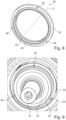
- FIG 6 an alternative embodiment of the adapter ring 26 is shown in perspective, which has the unchanged body 28 and the unchanged overlap 30.
- the circumferential bead 32 has three interruptions, which are delimited on both sides by edges 56 running in the axial direction, which protrude outwards from the body 28 in the radial direction.
- One of the receptacles 36 is formed by means of each interruption and the associated edges 56.
- the receptacles 36 and the extensions 34 are offset from each other by 120° with respect to the axis 2.
- FIG 8 another embodiment of the adapter ring 26 is shown in perspective, whereby the body 28 and the overlap 30 are not changed here either.
- the circumferential bead 32 is again present, in which three holes 58 running parallel to the axis 2 are made.
- the holes 58 are offset from one another by 120° with respect to the axis 2.
- each of the holes 58 a pin made of steel is pressed, forming the respective extension 34, as in Figure 9
- the projections 34 run parallel to the axis 2 and are located, as shown in Figure 10 shown in a sectional view along the axis 2, in each case in one of the corresponding receptacles 36, forming a clearance fit.
- the receptacles 36 are holes running parallel to the axis 2, which extend through the entire second component 12 in the axial direction.
Landscapes
- Engineering & Computer Science (AREA)
- General Engineering & Computer Science (AREA)
- Mechanical Engineering (AREA)
- Power Engineering (AREA)
- Rolling Contact Bearings (AREA)
Applications Claiming Priority (1)
| Application Number | Priority Date | Filing Date | Title |
|---|---|---|---|
| DE102022211158.3A DE102022211158B4 (de) | 2022-10-20 | 2022-10-20 | Lagereinheit |
Publications (2)
| Publication Number | Publication Date |
|---|---|
| EP4357632A1 true EP4357632A1 (fr) | 2024-04-24 |
| EP4357632B1 EP4357632B1 (fr) | 2026-04-22 |
Family
ID=88315968
Family Applications (1)
| Application Number | Title | Priority Date | Filing Date |
|---|---|---|---|
| EP23202616.1A Active EP4357632B1 (fr) | 2022-10-20 | 2023-10-10 | Unité de palier |
Country Status (4)
| Country | Link |
|---|---|
| US (1) | US20240229865A9 (fr) |
| EP (1) | EP4357632B1 (fr) |
| CN (1) | CN117917845A (fr) |
| DE (1) | DE102022211158B4 (fr) |
Families Citing this family (1)
| Publication number | Priority date | Publication date | Assignee | Title |
|---|---|---|---|---|
| EP4717938A1 (fr) * | 2024-09-25 | 2026-04-01 | KB Intellectual Property GmbH & Co. KG | Bride de palier avec un mécanisme d'évitement de rotation |
Citations (4)
| Publication number | Priority date | Publication date | Assignee | Title |
|---|---|---|---|---|
| US8303188B2 (en) * | 2007-12-05 | 2012-11-06 | Jtekt Corporation | Bearing apparatus |
| JP2013070510A (ja) * | 2011-09-22 | 2013-04-18 | Yaskawa Electric Corp | 回転電機 |
| EP3018800A1 (fr) * | 2013-07-05 | 2016-05-11 | Mitsubishi Electric Corporation | Machine électrique tournante |
| WO2021136834A1 (fr) * | 2019-12-31 | 2021-07-08 | Bombardier Transportation Gmbh | Machine électrique pourvue d'un ensemble de palier amovible |
Family Cites Families (9)
| Publication number | Priority date | Publication date | Assignee | Title |
|---|---|---|---|---|
| US2735734A (en) * | 1956-02-21 | Kalikow | ||
| US2926051A (en) * | 1957-10-01 | 1960-02-23 | Garrett Corp | Resilient bearing mount |
| US3881841A (en) * | 1973-11-29 | 1975-05-06 | Avco Corp | Damped compressor bearing mounting assembly |
| DE3044050C2 (de) * | 1980-11-22 | 1982-10-07 | Zahnradfabrik Friedrichshafen Ag, 7990 Friedrichshafen | Haltevorrichtung für ein Lager |
| FR3013760B1 (fr) * | 2013-11-26 | 2015-12-25 | Snecma | Dispositif pour le centrage et le guidage en rotation d'un arbre de turbomachine comprenant des moyens ameliores de retention de bague exterieure de palier |
| DE102015210058A1 (de) | 2015-06-01 | 2016-12-01 | Robert Bosch Gmbh | Handwerkzeugmaschine |
| DE102020106339A1 (de) | 2020-03-09 | 2021-09-09 | Schaeffler Technologies AG & Co. KG | Wälzlager, mit einem Innenring, einem Außenring und dazwischen aufgenommenen Wälzkörpern |
| DE102021205791A1 (de) * | 2021-06-08 | 2022-12-08 | Aktiebolaget Skf | Loslageranordnung |
| DE102021205788A1 (de) * | 2021-06-08 | 2022-12-08 | Aktiebolaget Skf | Loslageranordnung |
-
2022
- 2022-10-20 DE DE102022211158.3A patent/DE102022211158B4/de active Active
-
2023
- 2023-10-10 EP EP23202616.1A patent/EP4357632B1/fr active Active
- 2023-10-13 CN CN202311325359.1A patent/CN117917845A/zh active Pending
- 2023-10-19 US US18/381,819 patent/US20240229865A9/en active Pending
Patent Citations (4)
| Publication number | Priority date | Publication date | Assignee | Title |
|---|---|---|---|---|
| US8303188B2 (en) * | 2007-12-05 | 2012-11-06 | Jtekt Corporation | Bearing apparatus |
| JP2013070510A (ja) * | 2011-09-22 | 2013-04-18 | Yaskawa Electric Corp | 回転電機 |
| EP3018800A1 (fr) * | 2013-07-05 | 2016-05-11 | Mitsubishi Electric Corporation | Machine électrique tournante |
| WO2021136834A1 (fr) * | 2019-12-31 | 2021-07-08 | Bombardier Transportation Gmbh | Machine électrique pourvue d'un ensemble de palier amovible |
Also Published As
| Publication number | Publication date |
|---|---|
| DE102022211158B4 (de) | 2025-02-13 |
| US20240229865A9 (en) | 2024-07-11 |
| US20240133428A1 (en) | 2024-04-25 |
| EP4357632B1 (fr) | 2026-04-22 |
| DE102022211158A1 (de) | 2024-04-25 |
| CN117917845A (zh) | 2024-04-23 |
Similar Documents
| Publication | Publication Date | Title |
|---|---|---|
| DE68926698T2 (de) | Lageranordnung für eine Drehanoden-Röntgenröhre | |
| EP2999565B1 (fr) | Attachement d'outil | |
| DE102012023437B4 (de) | Rundlaufoptimiertes Werkzeugspannsystem für Dentalwinkelhandstücke und Dentalturbinen | |
| DE102021116607B3 (de) | Hydraulische Dehnspanneinrichtung | |
| EP1728306A2 (fr) | Ensemble stator de machine electrique | |
| EP4357632A1 (fr) | Unité de palier | |
| EP2463538A1 (fr) | Disque de serrage pour la liaison par friction d'éléments mécaniques rotatifs | |
| DE102013100129A1 (de) | Vorrichtung zur Klemmung einer Nabe auf einer Welle | |
| DE10311572B4 (de) | Anordnung zur Verbindung eines rohrförmigen Elementes mit einem darin erstreckten Körper | |
| WO2016037781A1 (fr) | Système de palier pour machines électriques | |
| EP0412954B1 (fr) | Flasque-palier pour un moteur électrique | |
| DE10008606B4 (de) | Kraftübertragungsmechanismus mit einem Sprengring zu dessen Montage | |
| WO2022057976A1 (fr) | Machine électrique et procédé de fabrication et de montage d'une machine électrique | |
| WO2020259868A1 (fr) | Motoréducteur, en particulier série de motoréducteurs, avec partie d'adaptation | |
| DE102020103231A1 (de) | Einstelleinrichtung und Verfahren zum Einstellen eines radialen Luftspalt-Abstandes bei einer elektrischen Maschine | |
| EP3623668A1 (fr) | Dispositif d'étanchéité de piston de pipetage à force de pression réglable d'une section de surface d'étanchéité | |
| DE112023005143T5 (de) | Läuferhülse, läufer und motor | |
| DE19926992B4 (de) | Buchse für einen Dämpfermechanismus | |
| DE102011079746A1 (de) | Axiallager, insbesondere für eine Schnellentspannvorrichtung zum Lösen eines scheibenförmigen Werkzeuges von der Arbeitsspindel einer elektrischen Handwerkzeugmaschine | |
| DE102022200757A1 (de) | Lageranordnung und Verfahren zur Herstellung einer Lageranordnung | |
| DE102015215492A1 (de) | Verfahren zum Herstellen einer variablen Turbinengeometrie eines Abgasturboladers | |
| DE102021123310A1 (de) | Rotor für eine elektrische Maschine | |
| DE102016014671A1 (de) | Triebkopf und Antriebstrangvorrichtung für ein Kraftfahrzeug | |
| EP3664260A1 (fr) | Moteur électrique à bride de montage | |
| DE102019110714B3 (de) | Läufer einer elektrischen Maschine und Verfahren zum Herstellen desselben |
Legal Events
| Date | Code | Title | Description |
|---|---|---|---|
| PUAI | Public reference made under article 153(3) epc to a published international application that has entered the european phase |
Free format text: ORIGINAL CODE: 0009012 |
|
| STAA | Information on the status of an ep patent application or granted ep patent |
Free format text: STATUS: THE APPLICATION HAS BEEN PUBLISHED |
|
| AK | Designated contracting states |
Kind code of ref document: A1 Designated state(s): AL AT BE BG CH CY CZ DE DK EE ES FI FR GB GR HR HU IE IS IT LI LT LU LV MC ME MK MT NL NO PL PT RO RS SE SI SK SM TR |
|
| STAA | Information on the status of an ep patent application or granted ep patent |
Free format text: STATUS: REQUEST FOR EXAMINATION WAS MADE |
|
| 17P | Request for examination filed |
Effective date: 20241017 |
|
| RBV | Designated contracting states (corrected) |
Designated state(s): AL AT BE BG CH CY CZ DE DK EE ES FI FR GB GR HR HU IE IS IT LI LT LU LV MC ME MK MT NL NO PL PT RO RS SE SI SK SM TR |
|
| GRAP | Despatch of communication of intention to grant a patent |
Free format text: ORIGINAL CODE: EPIDOSNIGR1 |
|
| STAA | Information on the status of an ep patent application or granted ep patent |
Free format text: STATUS: GRANT OF PATENT IS INTENDED |
|
| INTG | Intention to grant announced |
Effective date: 20260205 |
|
| GRAS | Grant fee paid |
Free format text: ORIGINAL CODE: EPIDOSNIGR3 |
|
| GRAA | (expected) grant |
Free format text: ORIGINAL CODE: 0009210 |
|
| STAA | Information on the status of an ep patent application or granted ep patent |
Free format text: STATUS: THE PATENT HAS BEEN GRANTED |
|
| AK | Designated contracting states |
Kind code of ref document: B1 Designated state(s): AL AT BE BG CH CY CZ DE DK EE ES FI FR GB GR HR HU IE IS IT LI LT LU LV MC ME MK MT NL NO PL PT RO RS SE SI SK SM TR |
|
| REG | Reference to a national code |
Ref country code: CH Ref legal event code: F10 Free format text: ST27 STATUS EVENT CODE: U-0-0-F10-F00 (AS PROVIDED BY THE NATIONAL OFFICE) Effective date: 20260422 Ref country code: GB Ref legal event code: FG4D Free format text: NOT ENGLISH |