EP4357651A1 - Soupape de surpression pour un entraînement de porte - Google Patents
Soupape de surpression pour un entraînement de porte Download PDFInfo
- Publication number
- EP4357651A1 EP4357651A1 EP23197636.6A EP23197636A EP4357651A1 EP 4357651 A1 EP4357651 A1 EP 4357651A1 EP 23197636 A EP23197636 A EP 23197636A EP 4357651 A1 EP4357651 A1 EP 4357651A1
- Authority
- EP
- European Patent Office
- Prior art keywords
- housing
- bearing element
- pressure relief
- relief valve
- plastic deformation
- Prior art date
- Legal status (The legal status is an assumption and is not a legal conclusion. Google has not performed a legal analysis and makes no representation as to the accuracy of the status listed.)
- Pending
Links
Images


Classifications
-
- F—MECHANICAL ENGINEERING; LIGHTING; HEATING; WEAPONS; BLASTING
- F16—ENGINEERING ELEMENTS AND UNITS; GENERAL MEASURES FOR PRODUCING AND MAINTAINING EFFECTIVE FUNCTIONING OF MACHINES OR INSTALLATIONS; THERMAL INSULATION IN GENERAL
- F16K—VALVES; TAPS; COCKS; ACTUATING-FLOATS; DEVICES FOR VENTING OR AERATING
- F16K15/00—Check valves
- F16K15/02—Check valves with guided rigid valve members
- F16K15/025—Check valves with guided rigid valve members the valve being loaded by a spring
-
- E—FIXED CONSTRUCTIONS
- E05—LOCKS; KEYS; WINDOW OR DOOR FITTINGS; SAFES
- E05F—DEVICES FOR MOVING WINGS INTO OPEN OR CLOSED POSITION; CHECKS FOR WINGS; WING FITTINGS NOT OTHERWISE PROVIDED FOR, CONCERNED WITH THE FUNCTIONING OF THE WING
- E05F3/00—Closers or openers with braking devices, e.g. checks; Construction of pneumatic or liquid braking devices
- E05F3/04—Closers or openers with braking devices, e.g. checks; Construction of pneumatic or liquid braking devices with liquid piston brakes
- E05F3/12—Special devices controlling the circulation of the liquid, e.g. valve arrangement
-
- F—MECHANICAL ENGINEERING; LIGHTING; HEATING; WEAPONS; BLASTING
- F16—ENGINEERING ELEMENTS AND UNITS; GENERAL MEASURES FOR PRODUCING AND MAINTAINING EFFECTIVE FUNCTIONING OF MACHINES OR INSTALLATIONS; THERMAL INSULATION IN GENERAL
- F16K—VALVES; TAPS; COCKS; ACTUATING-FLOATS; DEVICES FOR VENTING OR AERATING
- F16K27/00—Construction of housing; Use of materials therefor
- F16K27/02—Construction of housing; Use of materials therefor of lift valves
- F16K27/0209—Check valves or pivoted valves
-
- E—FIXED CONSTRUCTIONS
- E05—LOCKS; KEYS; WINDOW OR DOOR FITTINGS; SAFES
- E05Y—INDEXING SCHEME ASSOCIATED WITH SUBCLASSES E05D AND E05F, RELATING TO CONSTRUCTION ELEMENTS, ELECTRIC CONTROL, POWER SUPPLY, POWER SIGNAL OR TRANSMISSION, USER INTERFACES, MOUNTING OR COUPLING, DETAILS, ACCESSORIES, AUXILIARY OPERATIONS NOT OTHERWISE PROVIDED FOR, APPLICATION THEREOF
- E05Y2201/00—Constructional elements; Accessories therefor
- E05Y2201/20—Brakes; Disengaging means; Holders; Stops; Valves; Accessories therefor
- E05Y2201/23—Actuation thereof
- E05Y2201/232—Actuation thereof by automatically acting means
- E05Y2201/236—Actuation thereof by automatically acting means using force or torque
-
- E—FIXED CONSTRUCTIONS
- E05—LOCKS; KEYS; WINDOW OR DOOR FITTINGS; SAFES
- E05Y—INDEXING SCHEME ASSOCIATED WITH SUBCLASSES E05D AND E05F, RELATING TO CONSTRUCTION ELEMENTS, ELECTRIC CONTROL, POWER SUPPLY, POWER SIGNAL OR TRANSMISSION, USER INTERFACES, MOUNTING OR COUPLING, DETAILS, ACCESSORIES, AUXILIARY OPERATIONS NOT OTHERWISE PROVIDED FOR, APPLICATION THEREOF
- E05Y2800/00—Details, accessories and auxiliary operations not otherwise provided for
- E05Y2800/40—Physical or chemical protection
- E05Y2800/404—Physical or chemical protection against component faults or failure
-
- E—FIXED CONSTRUCTIONS
- E05—LOCKS; KEYS; WINDOW OR DOOR FITTINGS; SAFES
- E05Y—INDEXING SCHEME ASSOCIATED WITH SUBCLASSES E05D AND E05F, RELATING TO CONSTRUCTION ELEMENTS, ELECTRIC CONTROL, POWER SUPPLY, POWER SIGNAL OR TRANSMISSION, USER INTERFACES, MOUNTING OR COUPLING, DETAILS, ACCESSORIES, AUXILIARY OPERATIONS NOT OTHERWISE PROVIDED FOR, APPLICATION THEREOF
- E05Y2900/00—Application of doors, windows, wings or fittings thereof
- E05Y2900/10—Application of doors, windows, wings or fittings thereof for buildings or parts thereof
- E05Y2900/13—Type of wing
- E05Y2900/132—Doors
Definitions
- the invention relates to a pressure relief valve for a door drive, in particular for a door closer, a door drive, in particular a door closer with such a pressure relief valve and a method for producing such a pressure relief valve.
- Conventional pressure relief valves for door drives and in particular for door closers comprise, in particular consist of, four main components: a housing, a sealing element, a spring element and a bearing element.
- the housing contains a flow channel formed therein.
- the sealing element is movable in the housing between a closed position in which it closes the flow channel and an open position in which it releases the flow channel.
- the bearing element in particular just like the sealing element and the spring element, is inserted in an axial direction into a receiving area of the housing and fixed in the housing.
- the spring element is clamped within the housing between the bearing element and the sealing element in such a way that it preloads the sealing element from its open position to its closed position.
- the preload force thus obtained for the sealing element defines the response pressure of the pressure relief valve and depends essentially on the specific position in which the bearing element is fixed within the housing.
- the bearing element is fixed within the housing using a retaining clip.
- a retaining clip An example of such a clip is shown in FIG. 3 shown.
- the pressure relief valve 1 shown according to the prior art is formed from a housing 3, a sealing element 5, a spring element 7 and a bearing element 9.
- the housing 3 here has several recesses 3c.
- the bearing element 9 has clip contours or formations 9c.
- the bearing element 9 is pushed axially into a receiving area 3a of the housing 3 after the sealing element 5 and after the spring element 7 until the clip contours or formations 9c of the bearing element 9 engage in the recesses 3c of the housing 3.
- a relative position between the bearing element 9 and the housing 3 depends on the specific positioning of the recesses 3c in the housing 3 or the clip contours or formations 9c on the bearing element 9.
- a pressure relief valve for a door drive with the features of claim 1.
- Advantageous further developments for such a pressure relief valve can be found in the dependent claims.
- the The present invention also relates to a door drive with such a pressure relief valve and a manufacturing method for obtaining such a pressure relief valve.
- the pressure relief valve according to the invention is characterized in comparison to the conventional pressure relief valves described above in that the bearing element is fixed in the housing via at least one plastic deformation of the housing.
- the plastic deformation positions the bearing element and fixes it in the housing in such a way that the sealing element is prestressed into its closed position by the spring element with a predetermined force.
- the bearing element is not fixed to the housing in a fixed, predetermined relative position. Rather, the bearing element is fixed in exactly the relative position that leads to the preload force of the sealing element being maintained for the desired response pressure.
- This makes it possible to compensate for tolerances that occur during the manufacture of the individual components of the pressure relief valve by adjusting the selection of the specific relative positioning of the bearing element within the housing when assembling the pressure relief valve. This is done in a particularly simple manner, namely by adjusting the position of the respective plastic deformation of the housing along the receiving area of the housing.
- Plastic deformation is understood here to mean an actual deformation or reshaping of the housing.
- a mere recess or a certain predetermined shape of the housing as is the case, for example, with the design according to the prior art described above, does not fall under the term "deformation" as it is understood here.
- the bearing element has at least one recess in a radial outer circumference of the bearing element and the at least one plastic deformation of the housing projects into the at least one recess, in order to determine an axial relative positioning of the bearing element in relation to the housing.
- the respective plastic deformation and the respective recess form a positive connection. This is a particularly simple and reliable way of fixing the bearing element in the housing.
- the bearing element has at least two separate recesses of this type, while the housing has at least two separate corresponding plastic deformations.
- Each of the plastic deformations projects into one of the separate recesses. The formation of several pairs of recesses and corresponding deformations leads to a more reliable and firmer fixation of the bearing element in the housing.
- the separate recesses in the bearing element and the corresponding separate plastic deformations of the housing are evenly distributed around the radial outer circumference of the bearing element. This prevents the bearing element from tilting within the housing, which in turn counteracts fluctuations in the response pressure of the pressure relief valve.
- the separate recesses in the bearing element and the corresponding separate plastic deformations of the housing are each distributed in pairs opposite one another around the radial outer circumference of the bearing element.
- a pair of recesses and respective plastic deformations is opposite a corresponding pair of recesses and respective deformations.
- the bearing element preferably has a sleeve section which at least partially surrounds the spring element transversely to the longitudinal direction of the spring element. This enables a particularly compact and yet stable design of the pressure relief valve.
- the respective recess or recesses are formed by a respective opening in the sleeve section of the bearing element.
- Such openings are easy to form and allow the respective deformations to be formed through the entire wall of the sleeve section. This enables a particularly precise and reliable fixation of the bearing element within the receiving area of the housing.
- the bearing element is designed such that it can be moved continuously in the axial direction of the housing's receiving area before the at least one plastic deformation of the housing is formed.
- the bearing element is designed such that its relative positioning within the housing can be selected continuously, i.e. over a continuous range of relative positions. This enables particularly precise adjustment of the preload force obtained and thus of the response pressure of the pressure relief valve during its formation.
- At least one further fixation between the bearing element and the housing is preferably provided. This means that, in particular after the formation the plastic deformations and thus after a pre-fixing of the bearing element within the housing, at least one further fixation of the bearing element to the housing is formed. This enables a particularly reliable fixation of the bearing element at the respective relative position within the housing.
- At least one further fixation is formed by welding the housing to the bearing element.
- additional fixations are comparatively easy to form and ensure particularly reliable fixation of the bearing element.
- a further aspect of the present invention relates to a door drive, in particular a door closer, with at least one of the pressure relief valves described above.
- a door drive in particular a door closer, with at least one of the pressure relief valves described above.
- Yet another aspect of the present invention relates to a method for producing a pressure relief valve for a door drive, in particular for producing a pressure relief valve for a door closer.
- the present invention relates to a method for producing one of the pressure relief valves described above.
- Conventional manufacturing methods regularly comprise at least the following steps: providing a housing with a flow channel formed therein and a receiving area; introducing a sealing element and a spring element into the receiving area of the housing in such a way that the sealing element is provided in the housing so as to be movable between a closed position in which it closes the flow channel and an open position in which it releases the flow channel; positioning a bearing element in the receiving area of the housing in such a way that the spring element is clamped between the sealing element and the bearing element in such a way that it prestresses the sealing element from its open position into its closed position.
- the manufacturing method according to the invention is characterized in that the fixing of the bearing element within the housing takes place by the formation of at least one plastic deformation of the housing at a position in which the sealing element is prestressed into its closed position by the spring element with a predetermined force.
- the fixing of the bearing element does not take place at a relative position in the housing determined by previously formed recesses in the housing. Rather, according to the invention, the fixing takes place by forming at least one corresponding deformation of the housing, specifically at the relative position in which the predetermined preload force for the sealing element corresponding to the desired response pressure is obtained. This enables the simple and reliable compensation of possible tolerances in the manufacture of the individual components of the pressure relief valve during its assembly.
- the bearing element when assembling the pressure relief valve, the bearing element is pushed into the receiving area against the force of the spring element with a force corresponding to the predetermined preload force and the bearing element is fixed in the relative position thus obtained relative to the housing by forming at least one plastic deformation.
- This method is particularly easy to implement and enables reliable fixing of the bearing element in the corresponding relative position.
- At least one recess is formed in a radial outer circumference of the bearing element.
- the at least one plastic deformation of the housing is then formed in such a way that it projects into the at least one recess in order to establish an axial relative positioning of the bearing element in relation to the housing.
- the plastic deformation and the respective recess form a positive connection.
- At least two separate such recesses are formed in the radial outer circumference of the bearing element and at least two separate plastic deformations are formed in the housing such that each of the plastic deformations extends into one of the separate recesses.
- the separate recesses in the bearing element and the plastic deformations of the housing are formed evenly distributed around the radial outer circumference of the bearing element. This enables a particularly stable and reliable overall design for the pressure relief valve.
- the separate recesses in the bearing element and the deformations of the housing are each formed in pairs opposite one another and distributed around the radial outer circumference of the bearing element.
- the at least one plastic deformation of the housing is formed by means of a conical stamp.
- Such formation of the at least one plastic deformation is particularly simple and enables particularly reliable fixing of the bearing element.
- At least one further fixation is preferably formed between the bearing element and the housing. This results in a particularly reliable and long-lasting fixation of the bearing element.
- At least one further fixation is formed by welding, in particular by laser welding, the housing to the bearing element.
- Such a further fixation is relatively simple to form and yet reliable and durable.
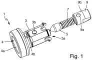
- the pressure relief valve 1 shown essentially consists of a housing 3, a sealing element 5, a spring element 7 and a bearing element 9.
- a flow channel 4 is formed in the housing 3. This runs from an inlet 4a to at least one outlet 4b.
- the sealing element 5 is inserted into a receiving area 3a of the housing 3 in such a way that it closes the flow channel 4 in a closed position (see FIG. 2A and FIG. 2B ).
- two opposite outlets 4b are formed for the flow channel 4.
- the specific design of the flow channel 4 and the sealing element 5 are not limited to this variant.
- only one outlet 4b can be formed, which is then provided in particular at the end of the receiving area, as is the case with the embodiment shown in FIG. 3 shown design is the case.
- the bearing element 9 is inserted axially into the receiving area 3a of the housing 3 and is or will be fixed in the housing 3 and that the spring element 7 is or will be clamped between the bearing element 9 and the sealing element 5 within the housing 3 in such a way that the spring element 7 pre-tensions the sealing element 5 in its closed position.
- the sealing element 5 must be movable against the pre-tensioning force of the spring element 7 from the closed position to an open position in which the sealing element 5 releases the flow channel 4.
- This movement into the open position must be caused by a pressure medium which penetrates through the inlet 4a into the flow channel 4 and, if the pressure of the medium is sufficient, the so-called response pressure, exceeds the preload force of the spring element 7.
- the pressure relief valve 1 thus enables the pressure medium to flow out through at least one outlet 4b as soon as the pressure of the pressure medium at the inlet 4a exceeds the response pressure.
- the level of the response pressure depends essentially on the force with which the spring element 7 preloads the sealing element 5 into its closed position.
- the bearing element 9 is fixed within the housing 3 via at least one plastic deformation 3b of the housing 3. This is only formed during the assembly of the pressure relief valve 1. As is particularly evident in FIG. 2 B As shown, in the present embodiment, two plastic deformations 3b are formed opposite one another, each of which extends into a corresponding recess 9a formed in the bearing element 9. The deformations 3b formed form a positive connection with the corresponding recesses 9a, which blocks any movement of the bearing element 9 relative to the housing 3.
- the bearing element 9 is pushed into the receiving area against the force of the spring element 5 with a force that corresponds to the preload force required for the respective response pressure. This is shown in FIG. 2A As soon as the bearing element 9 has reached its relative position in the housing 3 corresponding to the respective insertion force, the corresponding plastic deformations 3b of the housing 3 are formed.
- the insertion device comprises a number of forming tools corresponding to the number of deformations to be formed, which are positioned at the level of the recesses 9a of the bearing element 9 and, when the bearing element 9 is inserted, move along the outside of the housing 3 together with the respective recesses 9a.
- the forming tools are activated to form the respective plastic deformations 3b of the housing 3.
- the resulting plastic deformations 3b will therefore always protrude into the corresponding recesses 9a.
- the plastic deformations 3b are preferably formed by conical punches.
- the individual recesses 9a in the bearing element 9 and the corresponding deformations 3b of the housing 3 are or will be evenly distributed around the radial outer circumference of the bearing element 9 and in particular arranged in pairs opposite one another.
- the bearing element 9 has a sleeve section 9b which at least partially surrounds the spring element 7 transversely to its longitudinal direction.
- the recesses 9a described are or will be formed in the form of openings in the said sleeve section 9b.
- bearing element 9 is a self-contained piston element and/or to form the recesses 9a merely as depressions on the outer circumference of the bearing element 9.
- the bearing element 9 can be continuously displaced in the axial direction of the receiving area 3a of the housing 3 before the at least one plastic deformation 3b of the housing 3 is formed.
- the relative position of the bearing element 9 in relation to the housing 3 can preferably be freely selected over a continuous range of relative positions.
- At least one further fixation between the bearing element 9 and the housing 3 can be provided in addition to the plastic deformations 3b formed.
- An example of such a further fixation is welding, in particular laser welding, of the housing 3 to the bearing element 9.
- the pressure relief valve 1 shown here is further provided with a sealing ring 11, which, after the pressure relief valve 1 has been inserted into a corresponding door drive, enables a tight seal between the pressure relief valve 1 and the other components of the door drive.
- the present invention relates not only to such a pressure relief valve 1, but also to a corresponding manufacturing method as well as a door drive and in particular to a door closer with such a pressure relief valve 1.
Landscapes
- Engineering & Computer Science (AREA)
- General Engineering & Computer Science (AREA)
- Mechanical Engineering (AREA)
- Safety Valves (AREA)
Applications Claiming Priority (1)
| Application Number | Priority Date | Filing Date | Title |
|---|---|---|---|
| DE102022210953.8A DE102022210953A1 (de) | 2022-10-17 | 2022-10-17 | Überdruckventil für einen Türantrieb |
Publications (1)
| Publication Number | Publication Date |
|---|---|
| EP4357651A1 true EP4357651A1 (fr) | 2024-04-24 |
Family
ID=88092928
Family Applications (1)
| Application Number | Title | Priority Date | Filing Date |
|---|---|---|---|
| EP23197636.6A Pending EP4357651A1 (fr) | 2022-10-17 | 2023-09-15 | Soupape de surpression pour un entraînement de porte |
Country Status (2)
| Country | Link |
|---|---|
| EP (1) | EP4357651A1 (fr) |
| DE (1) | DE102022210953A1 (fr) |
Families Citing this family (2)
| Publication number | Priority date | Publication date | Assignee | Title |
|---|---|---|---|---|
| DE102024127821A1 (de) * | 2024-09-25 | 2026-03-26 | Thyssenkrupp Ag | Überdruckventil, Verdichter mit einem solchen Überdruckventil und Kältemittelkreislauf mit einem solchen Überdruckventil |
| DE102024127819A1 (de) * | 2024-09-25 | 2026-03-26 | Thyssenkrupp Ag | Verfahren zur Einstellung des Öffnungsdrucks eines Überdruckventils während der Montage und nach einem solchen Verfahren hergestelltes Überdruckventil, Verdichter in einem Kältemittelkreislauf mit einem solchen Überdruckventil sowie Kältemittelkreislauf mit einem solchen Überdruckventil |
Citations (7)
| Publication number | Priority date | Publication date | Assignee | Title |
|---|---|---|---|---|
| DE9010459U1 (de) * | 1990-07-11 | 1990-09-13 | Filterwerk Mann & Hummel Gmbh, 7140 Ludwigsburg | Ventil, insbesondere zur Umgehung eines Schmierölfilters einer Brennkraftmaschine |
| DE9007022U1 (de) * | 1990-06-23 | 1990-12-20 | Filterwerk Mann & Hummel Gmbh, 7140 Ludwigsburg | Ventil, insbesondere zur Umgehung eines Schmierölfilters einer Brennkraftmaschine |
| EP0601597A1 (fr) * | 1992-12-10 | 1994-06-15 | Josef Gartner & Co. | Soupape multifontionelle |
| DE4326968A1 (de) * | 1993-03-18 | 1994-09-22 | Stabilus Gmbh | Feststeller zum Feststellen relativ zueinander beweglicher Objekte |
| US6244295B1 (en) * | 1997-09-11 | 2001-06-12 | Robert Bosch Gmbh | Non-return valve, especially for a piston pump |
| EP1293633A2 (fr) * | 2001-09-13 | 2003-03-19 | GEZE GmbH | Ferme-porte |
| DE102009057327A1 (de) * | 2009-12-07 | 2011-06-30 | Schaeffler Technologies GmbH & Co. KG, 91074 | Rückschlagventil mit Rollierung und Beschneidung sowie Verfahren |
Family Cites Families (2)
| Publication number | Priority date | Publication date | Assignee | Title |
|---|---|---|---|---|
| DE102009053388A1 (de) * | 2009-11-14 | 2011-05-19 | Robert Bosch Gmbh | Ventil mit Demotageschutz sowie Montagehilfe |
| DE102013102336A1 (de) * | 2013-03-08 | 2014-09-11 | Dorma Gmbh + Co. Kommanditgesellschaft | Überdruckventil für eine Türschließvorrichtung |
-
2022
- 2022-10-17 DE DE102022210953.8A patent/DE102022210953A1/de active Pending
-
2023
- 2023-09-15 EP EP23197636.6A patent/EP4357651A1/fr active Pending
Patent Citations (7)
| Publication number | Priority date | Publication date | Assignee | Title |
|---|---|---|---|---|
| DE9007022U1 (de) * | 1990-06-23 | 1990-12-20 | Filterwerk Mann & Hummel Gmbh, 7140 Ludwigsburg | Ventil, insbesondere zur Umgehung eines Schmierölfilters einer Brennkraftmaschine |
| DE9010459U1 (de) * | 1990-07-11 | 1990-09-13 | Filterwerk Mann & Hummel Gmbh, 7140 Ludwigsburg | Ventil, insbesondere zur Umgehung eines Schmierölfilters einer Brennkraftmaschine |
| EP0601597A1 (fr) * | 1992-12-10 | 1994-06-15 | Josef Gartner & Co. | Soupape multifontionelle |
| DE4326968A1 (de) * | 1993-03-18 | 1994-09-22 | Stabilus Gmbh | Feststeller zum Feststellen relativ zueinander beweglicher Objekte |
| US6244295B1 (en) * | 1997-09-11 | 2001-06-12 | Robert Bosch Gmbh | Non-return valve, especially for a piston pump |
| EP1293633A2 (fr) * | 2001-09-13 | 2003-03-19 | GEZE GmbH | Ferme-porte |
| DE102009057327A1 (de) * | 2009-12-07 | 2011-06-30 | Schaeffler Technologies GmbH & Co. KG, 91074 | Rückschlagventil mit Rollierung und Beschneidung sowie Verfahren |
Also Published As
| Publication number | Publication date |
|---|---|
| DE102022210953A1 (de) | 2024-04-18 |
Similar Documents
| Publication | Publication Date | Title |
|---|---|---|
| EP4357651A1 (fr) | Soupape de surpression pour un entraînement de porte | |
| EP1490594B1 (fr) | Soupape d'injection de carburant | |
| EP1019628A1 (fr) | Dispositif pour transmettre un deplacement, injecteur comportant un tel dispositif et procede de production d'un tel element de transmission | |
| WO2009076928A2 (fr) | Piston en deux parties pour moteur à combustion interne | |
| DE102017222638A1 (de) | Magnetventil und Verfahren zur Herstellung eines Magnetventils | |
| EP1106817A2 (fr) | Soupape à géométrie de butée améliorée | |
| EP4563860B1 (fr) | Système d'ancrage, système de soupape et électrovanne et procédé de fabrication d'un système de soupape | |
| DE10321163B4 (de) | Verfahren zum Anbringen eines metallischen Dichtelements an einem Grundkörper eines Brennstoffeinspritzventils, sowie Brennstoffeinspritzventil | |
| DE10135556A1 (de) | Verfahren zum Montieren von Lagerringen | |
| DE10132756B4 (de) | Stellglied für Schaltelemente von Kraftstoff-Einspritzvorrichtungen | |
| DE102021100352A1 (de) | Ventil mit einem sich entlang einer Ventilachse erstreckendem Gehäusekörper und einem Stößel | |
| DE10142798C2 (de) | Lagerung für ein Piezoaktormodul in einem Common-Rail-Injektor | |
| DE102008002611A1 (de) | Abstützkörper, Rückschlagventil sowie Kraftstoff-Hochdruckpumpe | |
| EP1900932B1 (fr) | Injecteur destiné à la vaporisation de carburant | |
| WO2001025621A1 (fr) | Soupape d'injection de carburant pour moteurs a combustion interne et procede permettant de la produire | |
| DE102022118308B4 (de) | Druckregelventil | |
| DE102018125093B4 (de) | Verfahren zum Herstellen eines Klappenventils für die Abgasanlage eines Verbrennungsmotors | |
| DE102018131094A1 (de) | Ventil | |
| DE102010062077A1 (de) | Ventileinrichtung mit einem wenigstens abschnittsweise zylindrischen Bewegungselement | |
| DE102005059433A1 (de) | Druckregelventil mit Massivlager | |
| DE102022119474A1 (de) | Elektromagnetisch betätigbares Ventil mit durchströmbarer Ankerstange | |
| EP4215782A1 (fr) | Robinet-vanne et dispositif d'aide au montage | |
| WO2001034995A1 (fr) | Procede de production d'elements elastiques en elastomere | |
| DE102020107058A1 (de) | Verriegelungseinheit | |
| EP1573197A1 (fr) | Unite d'injecteur-pompe et procede pour regler la pression d'ouverture de celle-ci |
Legal Events
| Date | Code | Title | Description |
|---|---|---|---|
| PUAI | Public reference made under article 153(3) epc to a published international application that has entered the european phase |
Free format text: ORIGINAL CODE: 0009012 |
|
| STAA | Information on the status of an ep patent application or granted ep patent |
Free format text: STATUS: THE APPLICATION HAS BEEN PUBLISHED |
|
| AK | Designated contracting states |
Kind code of ref document: A1 Designated state(s): AL AT BE BG CH CY CZ DE DK EE ES FI FR GB GR HR HU IE IS IT LI LT LU LV MC ME MK MT NL NO PL PT RO RS SE SI SK SM TR |
|
| STAA | Information on the status of an ep patent application or granted ep patent |
Free format text: STATUS: REQUEST FOR EXAMINATION WAS MADE |
|
| 17P | Request for examination filed |
Effective date: 20241015 |
|
| RBV | Designated contracting states (corrected) |
Designated state(s): AL AT BE BG CH CY CZ DE DK EE ES FI FR GB GR HR HU IE IS IT LI LT LU LV MC ME MK MT NL NO PL PT RO RS SE SI SK SM TR |
|
| GRAP | Despatch of communication of intention to grant a patent |
Free format text: ORIGINAL CODE: EPIDOSNIGR1 |
|
| STAA | Information on the status of an ep patent application or granted ep patent |
Free format text: STATUS: GRANT OF PATENT IS INTENDED |
|
| INTG | Intention to grant announced |
Effective date: 20251022 |
|
| P01 | Opt-out of the competence of the unified patent court (upc) registered |
Free format text: CASE NUMBER: UPC_APP_0013033_4357651/2025 Effective date: 20251112 |
|
| GRAJ | Information related to disapproval of communication of intention to grant by the applicant or resumption of examination proceedings by the epo deleted |
Free format text: ORIGINAL CODE: EPIDOSDIGR1 |
|
| STAA | Information on the status of an ep patent application or granted ep patent |
Free format text: STATUS: REQUEST FOR EXAMINATION WAS MADE |
|
| GRAP | Despatch of communication of intention to grant a patent |
Free format text: ORIGINAL CODE: EPIDOSNIGR1 |
|
| STAA | Information on the status of an ep patent application or granted ep patent |
Free format text: STATUS: GRANT OF PATENT IS INTENDED |
|
| INTC | Intention to grant announced (deleted) | ||
| INTG | Intention to grant announced |
Effective date: 20260218 |
|
| GRAS | Grant fee paid |
Free format text: ORIGINAL CODE: EPIDOSNIGR3 |
|
| GRAA | (expected) grant |
Free format text: ORIGINAL CODE: 0009210 |
|
| STAA | Information on the status of an ep patent application or granted ep patent |
Free format text: STATUS: THE PATENT HAS BEEN GRANTED |