EP4357657B1 - Dispositif de soupape, machine de construction et procédé - Google Patents
Dispositif de soupape, machine de construction et procédé Download PDFInfo
- Publication number
- EP4357657B1 EP4357657B1 EP23204273.9A EP23204273A EP4357657B1 EP 4357657 B1 EP4357657 B1 EP 4357657B1 EP 23204273 A EP23204273 A EP 23204273A EP 4357657 B1 EP4357657 B1 EP 4357657B1
- Authority
- EP
- European Patent Office
- Prior art keywords
- thick
- connector
- matter
- media separation
- separation device
- Prior art date
- Legal status (The legal status is an assumption and is not a legal conclusion. Google has not performed a legal analysis and makes no representation as to the accuracy of the status listed.)
- Active
Links
Images



Classifications
-
- F—MECHANICAL ENGINEERING; LIGHTING; HEATING; WEAPONS; BLASTING
- F16—ENGINEERING ELEMENTS AND UNITS; GENERAL MEASURES FOR PRODUCING AND MAINTAINING EFFECTIVE FUNCTIONING OF MACHINES OR INSTALLATIONS; THERMAL INSULATION IN GENERAL
- F16L—PIPES; JOINTS OR FITTINGS FOR PIPES; SUPPORTS FOR PIPES, CABLES OR PROTECTIVE TUBING; MEANS FOR THERMAL INSULATION IN GENERAL
- F16L55/00—Devices or appurtenances for use in, or in connection with, pipes or pipe systems
- F16L55/26—Pigs or moles, i.e. devices movable in a pipe or conduit with or without self-contained propulsion means
- F16L55/46—Launching or retrieval of pigs or moles
-
- B—PERFORMING OPERATIONS; TRANSPORTING
- B08—CLEANING
- B08B—CLEANING IN GENERAL; PREVENTION OF FOULING IN GENERAL
- B08B9/00—Cleaning hollow articles by methods or apparatus specially adapted thereto
- B08B9/02—Cleaning pipes or tubes or systems of pipes or tubes
- B08B9/027—Cleaning the internal surfaces; Removal of blockages
- B08B9/04—Cleaning the internal surfaces; Removal of blockages using cleaning devices introduced into and moved along the pipes
- B08B9/053—Cleaning the internal surfaces; Removal of blockages using cleaning devices introduced into and moved along the pipes moved along the pipes by a fluid, e.g. by fluid pressure or by suction
- B08B9/055—Cleaning the internal surfaces; Removal of blockages using cleaning devices introduced into and moved along the pipes moved along the pipes by a fluid, e.g. by fluid pressure or by suction the cleaning devices conforming to, or being conformable to, substantially the same cross-section of the pipes, e.g. pigs or moles
-
- F—MECHANICAL ENGINEERING; LIGHTING; HEATING; WEAPONS; BLASTING
- F16—ENGINEERING ELEMENTS AND UNITS; GENERAL MEASURES FOR PRODUCING AND MAINTAINING EFFECTIVE FUNCTIONING OF MACHINES OR INSTALLATIONS; THERMAL INSULATION IN GENERAL
- F16L—PIPES; JOINTS OR FITTINGS FOR PIPES; SUPPORTS FOR PIPES, CABLES OR PROTECTIVE TUBING; MEANS FOR THERMAL INSULATION IN GENERAL
- F16L55/00—Devices or appurtenances for use in, or in connection with, pipes or pipe systems
- F16L55/26—Pigs or moles, i.e. devices movable in a pipe or conduit with or without self-contained propulsion means
- F16L55/28—Constructional aspects
- F16L55/30—Constructional aspects of the propulsion means, e.g. towed by cables
- F16L55/38—Constructional aspects of the propulsion means, e.g. towed by cables driven by fluid pressure
-
- E—FIXED CONSTRUCTIONS
- E04—BUILDING
- E04G—SCAFFOLDING; FORMS; SHUTTERING; BUILDING IMPLEMENTS OR AIDS, OR THEIR USE; HANDLING BUILDING MATERIALS ON THE SITE; REPAIRING, BREAKING-UP OR OTHER WORK ON EXISTING BUILDINGS
- E04G21/00—Preparing, conveying, or working-up building materials or building elements in situ; Other devices or measures for constructional work
- E04G21/02—Conveying or working-up concrete or similar masses able to be heaped or cast
- E04G21/04—Devices for both conveying and distributing
-
- F—MECHANICAL ENGINEERING; LIGHTING; HEATING; WEAPONS; BLASTING
- F16—ENGINEERING ELEMENTS AND UNITS; GENERAL MEASURES FOR PRODUCING AND MAINTAINING EFFECTIVE FUNCTIONING OF MACHINES OR INSTALLATIONS; THERMAL INSULATION IN GENERAL
- F16L—PIPES; JOINTS OR FITTINGS FOR PIPES; SUPPORTS FOR PIPES, CABLES OR PROTECTIVE TUBING; MEANS FOR THERMAL INSULATION IN GENERAL
- F16L2101/00—Uses or applications of pigs or moles
- F16L2101/10—Treating the inside of pipes
- F16L2101/12—Cleaning
Definitions
- the invention relates to a valve device, in particular a pig loader, for attachment to a high-density material conveying line of a construction machine for conveying high-density material, as well as to such a construction machine with such a valve device. Furthermore, the invention relates to a method for cleaning, in particular automatically, such a construction machine.
- DE 87 08 749 U1 discloses a device for introducing and removing pipe cleaning pigs into conveyor lines.
- a valve device is designed to be attached to a high-density material conveying line of a construction machine for conveying high-density material.
- the valve device can be connected to the high-density material conveying line.
- the valve device can be designed as a pig loader.
- the valve device has a base body and an actuating body that can be adjusted relative to the base body between a first switching position and a second switching position.
- the actuating body can be designed as a slide valve. It is conceivable for the actuating body to be designed as a rotary valve or revolver valve.
- the valve device further has an automatic, in particular active, transmission device with a receiving space for accommodating a media separation device.
- the media separation device can comprise a pig.
- the media separation device can comprise several pigs arranged side by side to form a pig package of the media separation device.
- the base body has a first connection and a second connection.
- the first connection is used to connect to a pump side of the construction machine, in particular to a pump-side thick matter pump line through which thick matter can flow of the construction machine.
- the actuator has a third connection for connecting the thick matter conveying line of the construction machine.
- the second connection and the receiving chamber are connected to each other. In other words, the automatic transmission device is connected to the second connection. In the first switching position, the first connection and the third connection are interconnected for a flow of at least thick matter between the first connection and the third connection.
- At least thick matter can mean that, in addition to the thick matter, other media and/or devices can flow through the first connection and the third connection.
- first switching position thick matter and/or liquid and/or a mixture of liquid and thick matter can flow through the first connection and the third connection one after the other, i.e., in a series connection.
- second connection and the third connection are interconnected for automatic transmission of the media separation device between the third connection and the transmission device, in particular via the second connection.
- the media separation device can therefore be transferred from the receiving chamber through the second connection into the third connection.
- the valve device advantageously enables the high-viscosity conveying line to be connected to the pump side of the construction machine in the first switching position, for example for high-viscosity conveying operation of the construction machine.
- the pump side can be separated from the high-viscosity conveying line in the second switching position in order to transfer the media separation device to the high-viscosity conveying line at a separation point formed by the valve device.
- This can advantageously be done automatically, so that time-consuming, manual cleaning of the high-viscosity conveying line can be dispensed with.
- manual loading of the high-viscosity conveying line with the media separation device can be dispensed with. This results in a reliably executable cleaning process that can be free from operator-related errors.
- Each connection can delimit a fluid channel.
- the thickener can be a building material.
- the thickener can be a paste-like mixture of different materials.
- the thickener can be mortar, cement, screed, or concrete, each in a mixable and/or conveyable state. In the mixable and/or conveyable state, the thickener has not yet hardened or set.
- the valve device expediently has a drive configured to adjust the base body and the actuating body relative to each other between the two switching positions.
- the drive can be automatically controlled. In this way, the adjustment of the base body and the actuating body relative to each other can advantageously be carried out automatically, in particular by means of a control device of the construction machine.
- the base body has a fourth connection.
- the fourth connection of the base body can be unused.
- the actuating body has a fourth connection, wherein the fourth connection of the actuating body is connected to the first connection in the second switching position and to an external environment of the valve device in the first switching position facing the base body.
- the fourth connection can therefore be present either on the actuating body or on the base body.
- a further transmission device can be connected to the fourth connection, by means of which a further media separation device can be introduced into a thick-material-carrying line of the construction machine.
- the actuating body has a fifth connection.
- the fifth connection In the first switching position, the fifth connection is connected to the second connection, whereby an additional thick material conveying line of the construction machine can be connected to the fifth connection or the fifth connection can be unused.
- the fifth connection is connected to a fourth connection of the base body in the first switching position and to the first connection in the second switching position.
- the valve device with a fifth connection can be used particularly flexibly, in particular in a power system of the boom rail with several thick material conveying lines.
- the valve device has a further, particularly passive, transmission device.
- Passive can mean “non-driven” or “non-driven.”
- the further transmission device has a further receiving space for accommodating a further media separation device, in particular a pig.
- the further media separation device can correspond to the media separation device already explained above.
- the fourth connection or the fifth connection is connected to the further receiving space, so that the further media separation device can be transferred between the further receiving space and the fourth connection or the fifth connection to the pump side.
- the further media separation device can advantageously be transferred into a thick matter pump line on the pump side of the construction machine.
- one media separation device can be arranged in each of the thick matter delivery line and the thick matter pump line on the pump side.
- All transmission devices can be of the same type. or be designed differently.
- the transmission device and at least one further transmission device can be designed to be active.
- the transmission device comprises a housing, wherein the housing defines the receiving space of the transmission device, in particular in a manner that is permeable to liquids and/or thick materials.
- the housing can advantageously ensure positioning of the media separation device in the receiving space.
- the housing can also shield the receiving space and/or a media separation device arranged therein from the external environment of the valve device.
- the transmission device comprises a piston.
- the piston is guided in the receiving space relative to the housing of the transmission device in such a way that, particularly in the second switching position, the media separation device can be transferred out of the receiving space by adjusting the piston relative to the housing.
- the piston can thus transmit an adjusting force to the media separation device.
- the transmission device comprises a sensor device for detecting at least one piston position of the piston relative to the housing. By means of the sensor device, a first piston end position and a second piston end position of the piston as well as—alternatively or additionally—an intermediate position of the piston between the piston end positions relative to the housing can preferably be detected.
- the transmission device comprises, in particular, a drive device, wherein the drive device is designed for automatic, in particular linear, adjustment of the piston relative to the housing.
- the drive device can comprise a hydraulic cylinder and—alternatively or additionally—a spindle drive. It is conceivable for the drive device to be electrically driven.
- the media separation device In the intermediate position of the piston, the media separation device can be moved out of the receiving chamber by means of the piston. In the intermediate position, the media separation device can be arranged in the connection to which the transmission device is connected. This connection can thus be sealed fluid-tight from the external environment of the valve device by means of the media separation device. If this connection is now connected to the thick matter conveying line by adjusting the actuating body, it can advantageously be prevented that thick matter from the thick matter conveying line enters the external environment via this connection.
- the piston is adjustable relative to a housing of the transmission device between a first and a second piston position along an adjustment direction.
- the piston In the first piston position, the piston is arranged along the adjustment direction at a distance from the connection connected to the receiving space.
- the piston is the second piston position along the adjustment direction in the respective connection such that this connection is fluid-tightly separated from the receiving space by means of the piston.
- the piston in the second piston position along the adjustment direction, the piston is flush with a separating surface of the valve device, wherein the base body and the actuating body contact one another in a sliding manner in the separating surface.
- a fluid-permeable passage can be formed in the separating surface between the piston and the respective connection in which the piston is received.
- the fluid-tight closure of the respective connection by means of the piston in the second piston position can be formed at a distance from the separating surface.
- an intermediate space can be formed between the media separation device adjusted by means of the piston and the sealing point formed by the piston, which intermediate space can be filled with fluid via a fluid channel. If this fluid is pressurized in the intermediate space, the media separation device can be adjusted away from the piston by the fluid pressure.
- connection on which the transmission device with piston is present expediently has an insertion bevel running around the inside at a connection end facing the transmission device.
- This insertion bevel can serve to center the media separation device.
- a sealing sleeve having a circumferential sealing lip can be arranged on the piston. In the second piston position, the sealing sleeve can be applied to the inside of the respective connection in order to close this connection in a fluid-tight manner.
- the insertion bevel can serve to ensure that the sealing lip can be inserted into the respective connection in a way that is gentle on the material and low in wear, in order to apply itself there on the inside.
- a plunger can also be arranged on the piston, by means of which the media separation device can be adjusted.
- an outer diameter of the plunger is smaller than an inner diameter of the respective connection.
- the plunger can end, along the adjustment direction of the piston, preferably at a distance from the sealing sleeve.
- the sealing sleeve can be made of an elastic material.
- the elastic material can be an elastomer and/or a rubber material.
- the elastic material can have a reinforcement. When subjected to fluid pressure, the sealing lip can be pressed radially against the inside of the respective port. This allows for a particularly pressure-resistant closure of the respective port in the second piston position.
- the base body has a fluid channel that opens into the second connection and through which fluid can flow.
- the fluid channel can be supplied with fluid by means of a pumping device of the construction machine.
- the pumping unit is preferably different from the thick matter pump unit.
- the valve device can additionally have a liquid valve, wherein the fluid channel can be closed in a fluid-tight manner by means of the liquid valve in order to separate the fluid channel from the second connection in a fluid-tight manner.
- the fluid channel opening into the second connection enables the media separation device to be pressurized with liquid in order to adjust the media separation device through the thick matter conveying line.
- the media separation device can be adjusted independently of the thick matter pump unit by means of the liquid guided through the fluid channel, so that the thick matter pump unit is available for adjusting another media separation device.
- the media separation device can be pressurized with liquid via the fluid channel when the piston of the transmission device is in its second piston position.
- the fluid channel can expediently have a liquid collection chamber.
- a venting device can be arranged on the liquid collection chamber, by means of which the fluid channel can be vented.
- a draining device can be connected to the liquid collection chamber, by means of which liquid can be drained from the fluid channel.
- the venting device and/or the draining device can be operated automatically and/or manually. Without venting by means of the venting option, a gas bubble, in particular an air bubble, can become trapped in the thick matter conveying line. When the thick matter conveying line is subjected to pressure, the gas in the gas bubble can be compressed and preloaded like a gas spring.
- the preload of the gas bubble can be suddenly released as soon as the air or gas bubble comes into pressure-equalizing contact with an external environment.
- thick matter can be accelerated explosively out of the thick matter conveying line, which can be dangerous for bystanders.
- the transfer device has a magazine for preloading media separation devices. Multiple elements of a pigging package of the media separation device can be preloaded into the magazine. This eliminates the need to manually insert multiple elements, in particular a pigging package, of the media separation device into the receiving space of the transfer device.
- a construction machine according to the invention is used to convey thick matter.
- the construction machine has a thick matter conveying line through which thick matter can flow.
- the construction machine has a pump side, on which, in particular, a thick matter pump line of the construction machine is arranged.
- the construction machine has a thick matter pumping unit, on which which the pump side is arranged.
- the thick matter pump unit is designed for supplying the thick matter delivery line with thick matter and/or liquid on the pump side.
- the construction machine has a valve device according to the invention as described above.
- the valve device is arranged between the pump side and the thick matter delivery line, in particular between the thick matter pump line and the thick matter delivery line.
- the pump side is connected to the first connection for a flow of thick matter.
- the thick matter delivery line is connected to the third connection for a flow of thick matter.
- the construction machine expediently has several transfer devices, by means of which several conveyor lines of the construction machine can be loaded with media separation devices.
- a conveyor line system of the construction machine with the multiple conveyor lines can be automatically supplied with media separation devices via the transfer devices.
- a method according to the invention serves for cleaning, in particular automatically, a construction machine according to the invention as described above.
- the advantages of the construction machine according to the invention outlined above can be exploited by means of the method.
- the method comprises a step a), according to which the actuating body is adjusted from its first switching position to its second switching position relative to the base body.
- the method further comprises a step b), which is carried out after step a).
- a media separation device is transferred from the transmission device to the third connection, so that the media separation device is arranged on or in the thick matter conveying line.
- the method further comprises a step c), which is carried out after step b).
- a pressure gradient falling across the media separation device is generated in order to adjust the media separation device relative to the valve device through the thick matter conveying line along the pressure gradient, displacing thick matter located in the third connection and/or in the thick matter conveying line.
- the media separation device is moved from the transmission device into the second connection, so that the second connection is sealed fluid-tight by the media separation device. This advantageously prevents the outflow of Thick matter from the thick matter conveying line via the second connection can be avoided if the actuator is moved to its second switching position when carrying out step a).
- step b) additionally comprises transferring a further media separation device from a further transmission device into the first connection, such that the further media separation device is arranged on or in the pump side, in particular on or in a pump-side thick matter pump line.
- step c) additionally comprises generating a pressure gradient falling across the further media separation device in order to adjust the further media separation device along the pressure gradient while displacing thick matter present in the first connection and/or on the pump side relative to the valve device on the pump side. In this way, thick matter present on the pump side can advantageously be removed from the pump side for cleaning the construction machine.
- step c) when step c) is carried out to generate the pressure gradient, thick matter present on the pump side is sucked away, in particular by means of the thick matter pump unit of the construction machine, so that the further media separation device is adjusted away from the valve device by the suction.
- a liquid is applied to the pump side and the further media separation device arranged on the pump side.
- the liquid is preferably applied to the further media separation device by means of the thick matter pump unit.
- the liquid can be fresh or process water.
- the further media separation device is thereby supplied with liquid in such a way that the further media separation device is adjusted back towards the valve device on the pump side and is then conveyed via the valve device into the further transfer device.
- the additional media separation device can first be moved away from the valve device and then, after the pumping direction of the thick matter pump unit has been reversed, moved back away from the thick matter pump unit and towards the valve device. After the additional media separation device has been moved back through the valve device, the additional media separation device can be collected by the additional transfer device.
- the additional media separation device can thus be introduced into a thick matter pump line present on the pump side via one and the same additional transfer device and also removed again after the thick matter pump line has been cleaned.
- a separate removal device on or near the thick matter pump unit is therefore no longer necessary.
- the actuating body when performing step c), is adjusted from its second switching position to its first switching position relative to the base body before the media separation device arranged on the thick matter conveying line is adjusted.
- the thick matter conveying line is pressurized with liquid via the pump side and the valve device.
- the second connection of the valve device when step b) is carried out, is separated in a fluid-tight manner from the receiving space of the transmission device connected to the second connection, in particular by means of a piston of the transmission device connected to the second connection.
- the second connection is also fluidly connected to a fluid line of the construction machine, in particular by means of a fluid valve of the valve device.
- the fluid line can be fed with fluid from a fluid pump unit of the construction machine.
- step c) is carried out, the thick matter conveying line and the media separation device arranged therein are pressurized with fluid via the fluid line in order to generate the pressure gradient falling across the media separation device. Consequently, the media separation device can be adjusted independently of the thick matter pump unit as a result of the pressurization with fluid via the fluid line.
- the thick matter pump unit can be used simultaneously to adjust another media separation device.
- a construction machine 100 according to the invention is intended for conveying thick material D.
- the thick material D can be a building material.
- the thick material D can be a paste-like mixture of different materials.
- the thick material D can be mortar, cement, screed, or concrete, each in a mixable and/or conveyable state. In the mixable and/or conveyable state, the thick material D has not yet hardened or set.
- the construction machine 100 has a high-density material conveying line 103 through which high-density material D can flow.
- the construction machine 100 also has a pump side 101. On the pump side 101, for example, a high-density material pumping line 102 of the construction machine 100 is arranged. Furthermore, the construction machine 100 has a high-density material pumping unit 105. The high-density material pumping unit 105 is arranged on the pump side 101.
- the high-density material pumping unit 101 is designed to supply the high-density material conveying line 101 with high-density material D and/or liquid F on the pump side.
- the construction machine 100 has a valve device 1 according to the invention.
- the valve device 1 is arranged between the pump side 101 and the high-density material conveying line 103.
- the valve device 1 is arranged between the thick matter pump line 102 and the thick matter delivery line 103.
- the pump side 101 is connected to a first port K1 for a flow of thick matter D.
- the thick matter delivery line 103 is connected to a third port K3 of the valve device 1 for a flow of thick matter D.
- the thick matter pumping unit 105 can have delivery cylinders with variable-volume delivery chambers. To change the volumes of the delivery chambers, in particular in opposite directions, the delivery cylinders can each have an adjustable delivery piston.
- the thick matter pumping unit 105 can also comprise an S-shaped bent S-pipe, one end of which is fluidly connected to a pressure port of the thick matter pumping unit 105 that functions as a pump outlet.
- the S-pipe can be arranged in a storage chamber of the thick matter pumping unit 105, which can be filled with thick matter D from above, for storing thick matter D.
- the S-pipe can be rotatably mounted at one end on the pressure port within the storage chamber.
- the variable-volume delivery chambers can open into the storage chamber.
- the S-pipe can be pivotable in the storage chamber relative to the delivery chambers such that it can be fluidly connected alternately to one of the delivery chambers. In this way, due to the counteraction of the pivoting of the S-pipe and a change in the volume of the pumping chambers, thick material D located in the storage chamber can be alternately sucked in by the pumping chambers and pumped out through the pumping chambers, through the S-pipe, and via the discharge nozzle. If a liquid F or a mixture of thick material F and liquid F is present in the storage chamber, the liquid F or the mixture can be pumped out in the same way. outside.
- a pumping direction of the thick matter pumping unit 105 can be reversible, so that thick matter D and/or liquid can be pumped selectively away from the thick matter pumping unit 105 in a conveying mode and toward the thick matter pumping unit 105 in a suction mode.
- An agitator can be arranged in the storage space of the thick matter pumping unit 105.
- the valve device 1 is designed for attachment to the thick material conveying line 103 of the building material machine 100.
- the valve device 1 can therefore be connected to the thick material conveying line 103.
- the valve device 1 can be a pig loader 12.
- the valve device 1 has a base body 2.
- the valve device 1 has an actuating body 3, which is adjustable relative to the base body 2 between a first switching position P1 and a second switching position P2.
- the actuating body 3 is designed, for example, like a slide valve. Either the base body 2 or the actuating body 3 can be attached to a substrate. It is also conceivable that neither the base body 2 nor the actuating body 3 are attached to the substrate.
- the valve device 1 has an automatic, for example active, transmission device 4, 4a.
- the transmission device 4, 4a has a receiving space 5 for receiving a media separation device M, M1.
- the media separation device M, M1 can comprise a pig.
- the media separation device M, M1 can comprise several pigs that are arranged one behind the other as elements of a pig package of the media separation device M, M1.
- Such a pig can function as a free piston that is adjustable, for example, in the thick matter delivery line 103 and/or in the thick matter pump line 102.
- the construction machine 100 can have several transmission devices 4, by means of which media separation devices M can be introduced into several delivery lines 103, although this is not shown in the figures.
- the base body 2 of the valve device 1 has a first connection K1, which is used for connection to the pump side 101 of the construction machine 100.
- the first connection K1 can be connected to the pump-side thick matter pump line 102 through which thick matter D can flow.
- the base body 2 also has a second connection K2.
- the actuating body 3 has a third connection K3 for connecting the thick matter delivery line 103 of the construction machine 100.
- the second connection K2 and the receiving space 5 of the automatic transmission device 4, 4a are connected to one another.
- the first connection K1 and the third connection K3 are connected to one another for a flow of at least thick matter D between the first connection K1 and the third connection K3.
- the second connection K2 and the third connection K3 are connected for an automatic transmission of the Media separation devices M, M1 are connected between the third connection K3 and the transmission device 4, 4a.
- Automatic transmission of the media separation device M, M1 in the second switching position P2 is possible, for example, via the second connection K2, i.e., through the second connection K2.
- the base body 2 has a fourth connection K4, which can be unused.
- the actuating body 3 has a fourth connection K4. If the fourth connection K4 is present on the actuating body 3, the fourth connection K4 is connected to the first connection K1 in the second switching position P2.
- the fourth connection K4 of the actuating body 3 is connected to an external environment of the valve device 1 in the first switching position P1, facing the base body 2.
- the actuating body 3 has, for example, a fifth connection K5.
- the fifth connection K5 is connected to the second connection K2 in the first switching position P1 and is unused in the second switching position P2.
- the fifth connection K5 is connected to the fourth connection K4 of the base body 2 in the first switching position P1 and to the first connection K1 in the second switching position P2.
- the valve device 1 has, for example, a further transmission device 4, 4b, which has a further receiving chamber 5 for receiving a further media separation device M, M2.
- the further transmission device 4, 4b can be passive.
- the further media separation device M, M2 can be designed in the manner of the media separation device M, M1. "Further” does not refer to an extension or expansion, but is to be understood as synonymous with "additional.”
- the fourth connection K4 or the fifth connection K5 can be connected to the further receiving chamber 5, so that the further media separation device M, M2 can be transferred between the further receiving chamber 5 and the fourth connection K4 or the fifth connection K5 to the pump side 101.
- the piston 7 is adjustable in the housing 6 in such a way that in the second switching position P2 the media separating device M, M1 can be moved out of the receiving space 5 by adjusting the piston 7 relative to the housing 6. is transferable.
- the transmission device 4, 4a can have a sensor device 8 for detecting at least one piston position of the piston 7 relative to the housing 6.
- the transmission device 4, 4a can have a drive device 9.
- the drive device 9 can be designed for automatically adjusting the piston 7 relative to the housing 6.
- the drive device 9 can have a hydraulic cylinder 10 and - alternatively or additionally - a spindle drive.
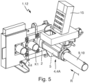
- the transmission device 4, 4a can have a magazine 15 for preloading media separation devices M, M1.
- the piston 7 is adjustable relative to the housing 6 of the transmission device 4, 4a between a first and a second piston position S1, S2 along an adjustment direction R.
- the piston 7 In the first piston position S1, the piston 7 is arranged along the adjustment direction R at a distance from the connection K2 connected to the receiving chamber 5.
- the piston 7 In the second piston position S2 along the adjustment direction R, the piston 7 is received in the connection K2 such that the connection K2 is separated from the receiving chamber 5 in a fluid-tight manner by means of the piston 7.
- the piston 7 is flush with a separating surface T of the valve device 1.
- a flush end of the piston 7 with the separating surface T can be fluid-permeable.
- the base body 2 and the actuating body 3 can touch one another in a sliding manner.
- the separating surface T can be designed as a separating plane.
- connection K2 to which the transmission device 4, 4a is connected in this case can have an internal insertion bevel.
- This insertion bevel can serve to center the piston 7 for its adjustment into the second piston position S2.
- the insertion bevel can also serve to center the media separation device M, M1 to be transmitted in the connection K2.
- an excess of the media separation device M1, M1 relative to the second connection K2 can be compensated.
- the piston 7 can have a sealing sleeve at one end facing away from the separation surface T, which can be applied internally to the connection K2.
- the piston 7 can have a plunger protruding in the adjustment direction R, which ends at a distance from the sealing sleeve in the adjustment direction R.
- a radial fluid-permeable space can be formed between the plunger and the connection K2.
- the media separation device M, M1 can be adjusted by means of the plunger.
- force transmission between piston 7 and media separation device M, M1 in the actuating direction R can take place at a distance from the sealing of the connection K2 by means of the sealing sleeve.
- a sealing plane defined by the sealing sleeve can thus be spatially separated from a tappet plane for force transmission, in particular along the actuating direction R. In the second piston position S2, the tappet plane can coincide with the separating surface T.
- a circumferential sealing lip of the sealing sleeve can, when the media separation device M, M1 is pressurized with liquid F be pushed radially outward due to the fluid pressure in order to reinforce a sealing effect.
- the piston 7 can be positioned in an intermediate position between the first and the second piston position S1, S2.
- the intermediate position can be detected by means of the sensor device 8.
- the intermediate position can be arranged such that the media separation device M, M1 is arranged in the second port K2 and touches the separating surface T when the piston 7 is in the intermediate position.
- the valve device 1 has, for example, a liquid valve.
- the fluid channel KF can be closed in a fluid-tight manner by means of the liquid valve in order to separate the fluid channel KF from the second connection K2 in a fluid-tight manner.
- the liquid valve can be arranged on the pump unit 104.
- the valve device 1 has, for example, a liquid collector chamber 11.
- the liquid collector chamber 11 can communicate fluidically with a venting device 13.
- the fluid channel KF can be vented by means of the venting device 13.
- the venting device 13 can be arranged at a highest location of the fluid channel KF along the direction of gravity.
- the liquid collector chamber 11 can also communicate fluidically with a drain device 14.
- the fluid channel KF can be emptied via the drain device 14.
- the venting device 13 can be manually actuated.
- the venting device 13 can be automatically actuated.
- the venting device 13 can be designed to be controllable, i.e., controllable and/or adjustable.
- the venting device 13 can have a float, by means of which the venting device 13 can be automatically actuated depending on the fill level of liquid F in the liquid collection chamber 11.
- the venting device 13 can have a ball valve and/or an electrically controllable valve. The same can apply to the drain device 14.
- a method according to the invention is used for cleaning the construction machine 100.
- the construction machine 100 can be cleaned automatically by means of the method.
- the method comprises a step a).
- the actuating body 3 is adjusted from its first switching position P1 to its second switching position P2 relative to the base body 2.
- the method also comprises a step b), which is carried out after step a).
- a media separation device M, M1 is transferred from the Transmission device 4, 4a into the third connection K3, so that the media separation device M, M1 is arranged on or in the thick matter conveying line 103.
- the method also comprises a step c), which is carried out after step b).
- a pressure gradient is generated across the media separation device M, M1.
- the pressure gradient is generated in order to adjust the media separation device M, M1 relative to the valve device 1 through the thick matter conveying line 103 along the pressure gradient, displacing thick matter D located in the third connection K3 and/or in the thick matter conveying line 103.
- the thick matter D located in the third connection K3 and - alternatively or additionally - in the thick matter conveying line 3 can be pushed outwards in order to remove the thick matter D from the third connection K3 or the thick matter conveying line 103.
- the media separation device M, M1 Prior to performing step a), the media separation device M, M1 can be moved from the transmission device 4, 4a into the second port K2 in order to seal the second port K2 in a fluid-tight manner by means of the media separation device M, M1.
- the media separation device M, M1 is moved up to the separation surface T.
- the second port K2 opposite the separation surface T can be sealed in a fluid-tight manner.
- step b) additionally comprises transferring a further media separation device M, M2 from a further transmission device 4, 4b into the first connection K1.
- the further media separation device M, M2 is transferred in such a way that the further media separation device M, M2 is arranged on or in the pump side 101, for example on or in the pump-side thick matter pump line 102.
- Step c) additionally comprises, for example, generating a pressure gradient falling across the further media separation device M, M2.
- the pressure gradient falling across the further media separation device M, M2 is generated in order to adjust the further media separation device M, M2 relative to the valve device 1 on the pump side along the pressure gradient, displacing thick matter D present in the first connection K1 and - alternatively or additionally - on the pump side.
- thick matter D present on the pump side is sucked off to generate the pressure drop.
- the suction of the thick matter D present on the pump side can be carried out, for example, by means of the thick matter pump unit 105 of the construction machine 100.
- the thick matter D present on the pump side is sucked off in such a way that the further media separation device M, M2 on the pump side is moved away from the valve device 1 by the suction. If the thick matter D, in particular substantially completely, on the pump side has been sucked off, when step c) is carried out, the pump side 101 and the further media separation device M, M2 arranged on the pump side are pressurized with a liquid F.
- the pressurization of the further media separation device M, M2 can be carried out by means of the thick matter pump unit 105.
- the liquid F can be in the form of fresh or process water.
- the pressurization of the second media separation device M, M2 takes place in such a way that the further media separation device M, M2 is adjusted back towards the valve device 1 on the pump side and is then conveyed via the valve device 1 into the further transmission device 4, 4b.
- the further transmission device 4, 4b can function as a collecting basket in which the further media separation device M, M2 is collected.
- the adjusting body 3 is adjusted from its second switching position P2 to its first switching position P1 relative to the base body 2 before the media separation device M, M1 arranged on the thick matter conveying line 103 is adjusted.
- the thick matter conveying line 103 is pressurized with liquid F via the pump side 102 and the valve device 1 in order to adjust the media separation device M, M1 arranged on the thick matter conveying line 103 through the thick matter conveying line 103.
- the second port K2 of the valve device 1 is fluid-tightly separated from the receiving space 5 of the transmission device 4, 4a connected to the second port K2. This fluid-tight separation can be achieved by means of the piston 7 of the transmission device 4, 4a.
- the second port K2 is also fluidly connected to the fluid line 106 of the construction machine 100 by means of the fluid valve of the valve device 1.
- the fluid line 106 is connected to the second port K2 via the fluid channel KF.
- the fluid channel KF can open into the second connection K2 between the transmission device 4, 4a and the separation surface T, in particular at an acute angle.
- the fluid line 106 can be supplied with fluid F from the fluid pump unit 104 of the construction machine 100.
- the thick matter conveying line 103 and the media separation device M, M1 arranged therein are supplied with fluid F, for example via the fluid line 106, in order to generate the pressure drop across the media separation device M, M1.
- the base body 2 has the first connection K1, the second connection K2 and the fourth connection K4.
- the actuating body 3 has the third connection K3 and the fifth connection K5.
- the media separation device 4, 4a is connected to the second connection K2.
- the pump side 101 is connected to the first connection K1.
- the fourth connection K4 is unused.
- the further transmission device 4, 4b can be connected to the fifth connection K5.
- the thick matter conveying line 103 is connected to the third connection K3.
- the liquid line 106 can, for example, open laterally via the fluid channel KF, in particular at an acute angle, into the second connection K2.
- the construction machine 100 is in a conveying operation in which thick matter D can be conveyed by means of the construction machine 100 from the thick matter pump unit 105 in the direction of the thick matter conveying line 103.
- the actuating body 3 is in its first switching position P1.
- the pump side 101 is connected to the thick matter conveying line 3 by means of the first connection K1 and the third connection K3.
- the connection K4, which is not used here, can be connected to the fifth connection K5 in the first switching position P1.
- the second connection K2 can be exposed opposite the transmission device 4, 4a.
- connection K1, K3, which are connected to one another in the first switching position P1 are fluid-tightly separated from the other connections K2, K4, K5.
- Ports K4 and K5, which are connected to each other in the first switching position P1 are fluid-tightly separated from the other ports K1, K2, and K3 in the first switching position P1.
- Port K2 is fluid-tightly separated from the other ports K1, K3, K4, and K5 in the first switching position P1.
- Fluid-tightly separated means that there is no direct fluid connection between the separated ports. Fluid-tightly separated ports can communicate with each other via an external environment, but not directly.
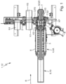
- Fig. 7 shows enlarged the same condition of the construction machine 100 as in Fig. 6 shown. According to Fig. 7 The further transmission device 4, 4b is connected to the fifth connection K5.
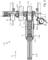
- step a) of the method is carried out, the adjusting body 3 is moved from its first switching position P1 to its second switching position P2 relative to the base body 2 in order to Fig. 8 This is followed by the execution of step b).
- the actuator 3 is in its second position P2
- the further media separation device M, M2 is adjusted by the further transmission device 4, 4b via the fifth connection K5 and the first connection K1 into the pump-side thick matter pump line 102.
- This adjustment in the direction of the thick matter pump unit 105 can be effected by suction by means of the thick matter pump unit 105.
- the further media separation device M, M2 is adjusted by means of liquid F conveyed by the thick matter pump unit 105 through the first connection K1 and the fifth connection K5 to the further transmission device 4, 4b.
- the further media separation device M, M2 can then be collected in the receiving space 5 of the further transmission device 4, 4b.
- the media separation device M, M1 is introduced into the thick matter conveying line 103 by means of the transmission device 4, 4a via the second connection K2 and the third connection K3.
- the actuating body 3 is now adjusted relative to the base body 2 into its first switching position P1 in order to Fig. 10 to achieve the state shown.
- a liquid column of liquid F already present in the thick matter pump line 102 as a result of the adjustment of the further media separation device M, M2 can thus be brought into contact with the media separation device M, M1.
- the media separation device M, M1 is pressurized with the liquid F.
- the media separation device M, M1 can be in contact with thick matter D present in the thick matter delivery line 103.
- an overpressure is now generated in the liquid column of liquid F in order to provide the pressure gradient for adjusting the media separation device M, M2.
- the media separation device M, M1 is adjusted along the thick matter delivery line 103 in order to displace the thick matter D from the delivery line 103.
- the second port K2 is connected to the third port K3.
- the first port is connected to the fifth port K5 in the second switching position P2.
- the unused fourth port K4 is free in the second switching position P2.
- the interconnected ports K2, K3 are fluid-tightly separated from the other ports K1, K4, K5 in the second switching position P2.
- the interconnected ports K1, K5 are fluid-tightly separated from the other ports K2, K3, K4 in the second switching position P2.
- the unused port K4 is not connected to any of the ports K1, K2, K3, K5 in the second switching position P2.
- the media separation device M, M1 can be sucked back to the valve device 101 by means of the thick matter pump unit 105 by reversing the pumping direction.
- the base body 2 has the first connection K1 and the second connection K2.
- the actuating body 3 has the third connection K3, the fourth connection K4, and the fifth connection K5.
- the transmission device 4, 4a is connected to the second connection K2.
- the further transmission device 4, 4b is connected to the fourth connection K4.
- the fluid channel KF, through which liquid F can flow, opens into the second connection K2 at an acute angle.
- the liquid F can be pumped into the fluid channel KF by means of the pump unit 104 through the liquid line 106.
- the actuator 3 is in its first switching position P1.
- the construction machine 100 can be in a conveying mode in which thick matter can be conveyed by means of the thick matter pump unit 105 through the pump-side conveying line 102, the first connection K1, the third connection K3 and the thick matter conveying line 103.
- a distribution system of the construction machine 100 can be arranged on a thick matter conveying line 103 opposite the thick matter pumping unit 105.
- the conveyed thick matter D can be conveyed into a molded casting mold by means of the distribution system.
- the second port K2 is connected to the fifth port K5.
- the first port K1 is connected to the third port K3.
- the fourth port K4 is exposed in the first switching position P1.
- the ports K2 and K5, which are connected to one another in the first switching position P1, are fluid-tightly separated from the other ports K1, K3 and K4.
- the ports K1 and K3, which are connected to one another in the first switching position P1, are fluid-tightly separated from the other ports K2, K5 and K4.
- the exposed port K4 is separated from the other ports K1, K2, K3 and K5 in the first switching position P1.
- step a) of the method is carried out, the adjusting body 3 is moved to its second switching position P2 in order to Fig. 12 shown state. Subsequently, step b) is carried out. Accordingly, the media separation device M, M1 is introduced from the transmission device 4, 4a via the second connection K2 and via the third connection K3 into the thick matter conveying line 103. At the same time, the further media separation device M, M2 can be introduced from the further transmission device 4, 4b via the fourth connection K4 and the first connection K1 into the pump-side thick matter pumping line 102. In the second switching position P2, the second connection K2 and the third connection K3 are connected to one another.
- the first connection K1 and the fourth connection K4 are also connected to one another.
- the fifth connection K5 is unused in the second switching position P2.
- the ports K1, K4 connected to one another in the second switching position P2 are separated from the other ports K2, K3, K5.
- the ports K2, K3 connected to one another in the second switching position P2 are separated from the other ports K1, K4, K5.
- the port K5 unused in the second switching position is separated from the other ports K1, K2, K3, K4.
- the thick matter D displaced by means of the further media separation device M, M2 can be drained, in particular by means of a drain device of the thick matter pumping unit 105.
- the drain device can automatically release or close the storage space of the thick matter pumping unit 105 downwards.
- the further media separation device M, M2 can be pressurized with liquid F by means of the thick matter pump unit 105.
- the further media separation device M, M2 is moved back from the thick matter pump unit 105 towards the valve device through the pump-side thick matter pump line 102.
- the further media separation device M, M2 can be collected in the further transmission device 4, 4b, as shown in Fig. 13 is shown.
- the pump-side thick matter pump line 102 can be flushed with liquid F, which is pumped through the thick matter pump line 102 by means of the thick matter pump unit 105.
- the media separation device M, M1 arranged on the thick matter conveying line 103 can be supplied with liquid F via the fluid channel 102, as shown in Fig. 13 also recognizable.
- the media separation device M, M1 can be supplied with liquid via the fluid channel 106 during the adjustment of the further media separation device 4, 4b in the direction of the thick matter pump unit 105 and/or simultaneously with the adjustment of the further media separation device M, M2 back from the thick matter pump unit 105 in the direction of the valve device 1.
- the Media separation device M, M1 is displaced away from the valve device 1 by displacing thick matter D present in the thick matter conveying line 103.
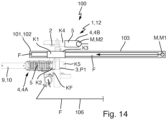
- the actuating body 3 can be moved back to its first switching position P1 in order to Fig. 14 to achieve the state shown.
- a liquid column present in the thick matter conveying line 103 can be connected to a liquid column present in the pump-side thick matter pumping line 102 as a result of the adjustment of the adjusting body 3 to its first position P1.
- the liquid column resulting from the connection can then be sucked away by means of the thick matter pumping unit 105 in order to adjust the further media separation device M, M1 in the direction of the thick matter pumping unit 105. In this way, it is possible to prevent the further media separation device M, M1 from entering the formed casting mold, which can be filled with thick matter D during conveying operation of the construction machine 100.
Landscapes
- Engineering & Computer Science (AREA)
- General Engineering & Computer Science (AREA)
- Mechanical Engineering (AREA)
- Chemical & Material Sciences (AREA)
- Combustion & Propulsion (AREA)
- Physics & Mathematics (AREA)
- Fluid Mechanics (AREA)
- Fluid-Pressure Circuits (AREA)
Claims (15)
- Dispositif de vanne (1), notamment chargeur de racleur (12), destiné à être rattaché à une conduite de transport de matière épaisse (103) d'une machine de construction (100) pour transporter de la matière épaisse (D), le dispositif de vanne (1) présentant :- un corps de base (2) et un corps de réglage (3), notamment de type coulisse, pouvant être déplacé par rapport au corps de base (2) entre une première position de commutation (P1) et une deuxième position de commutation (P2), et- un dispositif de transfert automatique (4, 4A), notamment actif, avec un espace de réception (5) pour recevoir un dispositif de séparation de milieux (M, M1), notamment un racleur,- le corps de base (2) présentant un premier raccord (K1) pour le raccordement à un côté de pompage (101) de la machine de construction (100), notamment à une conduite de pompage de matière épaisse (102) côté pompage de la machine de construction (100) pouvant être traversée par de la matière épaisse (D), et un deuxième raccord (K2),- le corps de réglage (3) présentant un troisième raccord (K3) pour raccorder la conduite de transport de matière épaisse (103) de la machine de construction (100),- le deuxième raccord (K2) et l'espace de réception (5) étant raccordés l'un à l'autre,- dans la première position de commutation (P1), le premier raccord (K1) et le troisième raccord (K3) étant reliés l'un à l'autre pour un écoulement au moins de matière épaisse (D) entre le premier raccord (K1) et le troisième raccord (K3),- dans la deuxième position de commutation (P2), le deuxième raccord (K2) et le troisième raccord (K3) étant reliés l'un à l'autre pour un transfert automatique du dispositif de séparation de milieux (M, M1) entre le troisième raccord (K3) et le dispositif de transfert (4, 4A), notamment par l'intermédiaire du deuxième raccord (K2),caractérisé en ce que- le dispositif de transfert (4, 4A, 4B) présente un piston (7) qui est guidé de manière réglable dans l'espace de réception (5) par rapport à un boîtier (6) du dispositif de transfert (4, 4A, 4B) de telle sorte que, notamment dans la deuxième position de commutation (P2), le dispositif de séparation de milieux (M, M1, M2) peut être transféré hors de l'espace de réception (5) par déplacement du piston (7) par rapport au boîtier (6), en ce que- le piston (7) peut être déplacé par rapport à un boîtier (6) du dispositif de transfert (4, 4A, 4B) entre une première et une deuxième position de piston (S1, S2) le long d'une direction de réglage (R), en ce que- le piston (7) est agencé dans la première position de piston (S1) le long de la direction de réglage (R) à distance du raccord (K2, K4, K5) raccordé à l'espace de réception (5), et en ce que- le piston (7) est reçu dans la deuxième position de piston (S2) le long de la direction de réglage (R) dans le raccord respectif (K2, K4, K5) de telle sorte que ce raccord (K2, K4, K5) est séparé de manière étanche aux fluides de l'espace de réception (5) au moyen du piston (7).
- Dispositif de vanne (1) selon la revendication précédente,- le corps de base (2) présentant un quatrième raccord (K4), notamment inutilisé, ou- le corps de réglage (3) présentant un quatrième raccord (K4), le quatrième raccord (K4) étant relié au premier raccord (K1) dans la deuxième position de commutation (P2) et à un environnement extérieur du dispositif de vanne (1) en face du corps de base (2) dans la première position de commutation (P1).
- Dispositif de vanne (1) selon l'une quelconque des revendications précédentes,- le corps de réglage (3) présentant un cinquième raccord (K5),- le cinquième raccord (K5) étant relié au deuxième raccord (K2) dans la première position de commutation (P1), ou le cinquième raccord (K5) étant relié à un quatrième raccord (K4) du corps de base (2) dans la première position de commutation (P1) et au premier raccord (K1) dans la deuxième position de commutation (P2).
- Dispositif de vanne (1) selon l'une quelconque des deux revendications précédentes,- le dispositif de vanne (1) présentant un autre dispositif de transfert (4, 4B), notamment passif, avec un autre espace de réception (5) pour recevoir un autre dispositif de séparation de milieux (M, M2), notamment un racleur,- le quatrième raccord (K4) ou le cinquième raccord (K5) étant raccordé à l'autre espace de réception (5), de telle sorte que l'autre dispositif de séparation de milieux (M, M2) peut être transféré entre l'autre espace de réception (5) et le quatrième raccord (K4) ou le cinquième raccord (K5) vers le côté pompage (101).
- Dispositif de vanne (1) selon l'une quelconque des revendications précédentes,
le dispositif de transfert (4, 4A, 4B) présentant un boîtier (6), le boîtier (6) délimitant l'espace de réception (5) du dispositif de transfert (4, 4A, 4B), notamment de manière perméable aux liquides et/ou aux matières épaisses. - Dispositif de vanne (1) selon l'une quelconque des revendications précédentes,- le dispositif de transfert (4, 4A, 4B) présentant un dispositif de détection (8) pour détecter au moins une position de piston du piston (7) par rapport au boîtier (6), et/ou- le dispositif de transfert (4, 4A, 4B) présentant un dispositif d'entraînement (9), le dispositif d'entraînement (9) étant réalisé pour déplacer automatiquement le piston (7) par rapport au boîtier (6), notamment le dispositif d'entraînement (9) présentant un vérin hydraulique (10) et/ou un entraînement à broche.
- Dispositif de vanne (1) selon la revendication précédente,- le piston (7) se terminant dans la deuxième position de piston (S2) le long de la direction de réglage (R) à fleur d'une surface de séparation (T) du dispositif de vanne (1), le corps de base (2) et le corps de réglage (3) étant en contact l'un avec l'autre de manière coulissante dans la surface de séparation (T).
- Dispositif de vanne (1) selon l'une quelconque des revendications précédentes,- le corps de base (2) présentant un canal de fluide (KF) débouchant dans le deuxième raccord (K2) et pouvant être traversé par un liquide (F), notamment le canal de fluide (KF) pouvant être alimenté en liquide (F) au moyen d'une unité de pompage (104) de la machine de construction (100),- notamment le dispositif de vanne (1) présentant une vanne de liquide, le canal de fluide (KF) pouvant être fermé de manière étanche aux fluides au moyen de la vanne de liquide afin de séparer de manière étanche aux fluides le canal de fluide (KF) du deuxième raccord (K2).
- Dispositif de vanne (1) selon l'une quelconque des revendications précédentes,
le dispositif de transfert (4, 4A, 4B) présentant un magasin (15) pour précharger des dispositifs de séparation de milieux (M, M1, M2). - Machine de construction (100) pour transporter de la matière épaisse (D), la machine de construction (100) présentant,- une conduite de transport de matière épaisse (103) pouvant être traversée par de la matière épaisse (D),- un côté de pompage (101), sur lequel est notamment agencée une conduite de pompage de matière épaisse (102) de la machine de construction (100), et- une unité de pompage de matière épaisse (105), sur laquelle est agencée le côté de pompage (101), l'unité de pompage de matière épaisse (105) étant réalisée pour alimenter, côté pompage, la conduite de transport de matière épaisse (101) en matière épaisse (D) et/ou en liquide (F),- un dispositif de vanne (1) selon l'une quelconque des revendications précédentes, le dispositif de vanne (1) étant agencé entre le côté de pompage (101) et la conduite de transport de matière épaisse (103), notamment entre la conduite de pompage de matière épaisse (102) et la conduite de transport de matière épaisse (103),- le côté de pompage (101) étant raccordé au premier raccord (K1) pour un écoulement de matière épaisse (D) et la conduite de transport de matière épaisse (103) étant raccordée au troisième raccord (K3) pour un écoulement de matière épaisse (D).
- Procédé de nettoyage, notamment automatique, d'une machine de construction (100) selon la revendication précédente, le procédé présentant les étapes suivantes :a) le déplacement du corps de réglage (3) de sa première position de commutation (P1) à sa deuxième position de commutation (P2) par rapport au corps de base (2),b) temporellement après l'exécution de l'étape a) : le transfert d'un dispositif de séparation de milieux (M, M1) depuis le dispositif de transfert (4, 4A) dans le troisième raccord (K3) de telle sorte que le dispositif de séparation de milieux (M, M1) soit agencé sur/dans la conduite de transport de matière épaisse (103),c) temporellement après l'exécution de l'étape b) : la génération d'un gradient de pression descendant à travers le dispositif de séparation de milieux (M, M1) pour déplacer le dispositif de séparation de milieux (M, M1) par rapport au dispositif de vanne (1) à travers la conduite de transport de matière épaisse (103) le long du gradient de pression en refoulant de la matière épaisse (D) se trouvant dans le troisième raccord (K3) et/ou dans la conduite de transport de matière épaisse (103).
- Procédé selon la revendication précédente,- l'étape b) présentant en outre :
le transfert d'un autre dispositif de séparation de milieux (M, M2) depuis un autre dispositif de transfert (4, 4B) dans le premier raccord (K1) de telle sorte que l'autre dispositif de séparation de milieux (M, M2) soit agencé sur/dans le côté pompage (101), notamment sur une conduite de pompage de matière épaisse (102) côté pompage ;- l'étape c) comprenant en outre :
la génération d'un gradient de pression descendant à travers l'autre dispositif de séparation de milieux (M, M2), afin de déplacer l'autre dispositif de séparation de milieux (M, M2) par rapport au dispositif de vanne (1), côté pompage, le long du gradient de pression, en refoulant la matière épaisse (D) présente dans le premier raccord (K1) et/ou côté pompage. - Procédé selon la revendication précédente,
lors de l'exécution de l'étape c)- pour générer le gradient de pression, de la matière épaisse (D) présente côté pompage étant aspirée, notamment au moyen de l'unité de pompage de matière épaisse (105) de la machine de construction (100), de telle sorte que l'autre dispositif de séparation de milieux (M, M2) est déplacé côté pompage par l'aspiration en s'éloignant du dispositif de vanne (1), et- lorsque la matière épaisse (D) a été aspirée, notamment essentiellement en totalité, côté pompage, le côté pompage (101) et l'autre dispositif de séparation de milieux (M, M2) agencé côté pompage sont sollicités, notamment au moyen de l'unité de pompage de matière épaisse (105), avec un liquide (F), notamment avec de l'eau fraîche ou de l'eau industrielle, de telle sorte que l'autre dispositif de séparation de milieux (M, M2) est ramené côté pompage vers le dispositif de vanne (1) et est ensuite transporté dans l'autre dispositif de transfert (4, 4B) par l'intermédiaire du dispositif de vanne (1). - Procédé selon l'une quelconque des deux revendications précédentes,- lors de l'exécution de l'étape c), un déplacement du corps de réglage (3) de sa deuxième position de commutation (P2) dans sa première position de commutation (P1) par rapport au corps de base (2) étant effectué temporellement avant le déplacement du dispositif de séparation de milieux (M, M1) agencé sur la conduite de transport de matière épaisse (103),- pour déplacer le dispositif de séparation de milieux (M, M1) agencé sur la conduite de transport de matière épaisse (103), la conduite de transport de matière épaisse (103) étant sollicitée avec du liquide (F) à travers la conduite de transport de matière épaisse (103) par l'intermédiaire du côté pompage (102) et du dispositif de vanne (1).
- Procédé selon l'une quelconque des trois revendications précédentes,- lors de la réalisation de l'étape b)- le deuxième raccord (K2) du dispositif de vanne (1) étant séparé de manière étanche aux fluides, notamment au moyen d'un piston (7) du dispositif de transfert (4, 4A) raccordé au deuxième raccord (K2), de l'espace de réception (5) du dispositif de transfert (4, 4A) raccordé au deuxième raccord (K2),- le deuxième raccord (K2) étant relié, notamment au moyen d'une vanne de liquide du dispositif de vanne (1), de manière à conduire le fluide, à une conduite de liquide (106) de la machine de construction (100), notamment la conduite de liquide (106) étant approvisionnée en liquide (F) par une unité de pompage de liquide (104) de la machine de construction (100), et- lors de l'exécution de l'étape c), la conduite de transport de matière épaisse (103) et le dispositif de séparation de milieux (M, M1) agencé dans celle-ci étant sollicités avec du liquide (F) par l'intermédiaire de la conduite de liquide (106) afin de générer le gradient de pression descendant à travers le dispositif de séparation de milieux (M, M1).
Applications Claiming Priority (1)
| Application Number | Priority Date | Filing Date | Title |
|---|---|---|---|
| DE102022211187.7A DE102022211187B4 (de) | 2022-10-21 | 2022-10-21 | Ventileinrichtung, Baumaschine und Verfahren |
Publications (2)
| Publication Number | Publication Date |
|---|---|
| EP4357657A1 EP4357657A1 (fr) | 2024-04-24 |
| EP4357657B1 true EP4357657B1 (fr) | 2025-05-21 |
Family
ID=88417309
Family Applications (1)
| Application Number | Title | Priority Date | Filing Date |
|---|---|---|---|
| EP23204273.9A Active EP4357657B1 (fr) | 2022-10-21 | 2023-10-18 | Dispositif de soupape, machine de construction et procédé |
Country Status (2)
| Country | Link |
|---|---|
| EP (1) | EP4357657B1 (fr) |
| DE (1) | DE102022211187B4 (fr) |
Families Citing this family (1)
| Publication number | Priority date | Publication date | Assignee | Title |
|---|---|---|---|---|
| DE102023133970A1 (de) * | 2023-12-05 | 2025-06-05 | Putzmeister Engineering Gmbh | Einbringungseinrichtung, System und Verfahren |
Family Cites Families (4)
| Publication number | Priority date | Publication date | Assignee | Title |
|---|---|---|---|---|
| DE8708749U1 (de) * | 1987-06-24 | 1987-08-20 | Bergwerksverband Gmbh, 4300 Essen | Einrichtung zum Ein- und Ausschleusen von Rohrreinigungsmolchen |
| EP0409955A4 (en) * | 1989-02-08 | 1992-03-11 | Barry Bros. Specialised Services Pty Ltd | Apparatus for cleaning the inner surfaces of tubes in operating multi-tube heat transfer devices |
| DE4436247A1 (de) * | 1994-10-11 | 1996-04-18 | Putzmeister Maschf | Anordnung zum Reinigen von Dickstoff-Förderrohren |
| DE102006020776A1 (de) * | 2006-05-03 | 2007-11-08 | Putzmeister Ag | Vorrichtung zur Einführung von Reinigungskörpern in eine Förderleitung |
-
2022
- 2022-10-21 DE DE102022211187.7A patent/DE102022211187B4/de active Active
-
2023
- 2023-10-18 EP EP23204273.9A patent/EP4357657B1/fr active Active
Also Published As
| Publication number | Publication date |
|---|---|
| DE102022211187A1 (de) | 2024-05-02 |
| DE102022211187B4 (de) | 2024-08-08 |
| EP4357657A1 (fr) | 2024-04-24 |
Similar Documents
| Publication | Publication Date | Title |
|---|---|---|
| DE69828452T2 (de) | Innenhochdruckumformungspresse | |
| EP0022251B1 (fr) | Vanne pour conduite avec un corps incorporable pour l'échange du passe-diable nettoyeur, pouvant être raccordé à des tuyaux dans lesquels circulent des liquides épais sous pression, en particulier du béton | |
| DE102007007588A1 (de) | Pulverfördervorrichtung für Sprühbeschichtungspulver | |
| DE10353968A1 (de) | Beschichtungspulver-Fördervorrichtung und -Förderverfahren | |
| EP3126094B1 (fr) | Installation de coupe à suspension aqueuse abrasive | |
| DE2726165A1 (de) | Vorrichtung zur erhoehung der ausfahrgeschwindigkeit der kolbenstange eines druckmitteldruck verwendenden hubzylinders | |
| EP0805273A2 (fr) | Pompe à matières épaisses | |
| WO2015172981A1 (fr) | Système hydraulique | |
| DE102022211187B4 (de) | Ventileinrichtung, Baumaschine und Verfahren | |
| EP3242017B2 (fr) | Multiplicateur de pression en tant que visseuse | |
| DE19906409B4 (de) | Dosiervorrichtung sowie Verfahren zum Betreiben einer Dosiervorrichtung | |
| EP4643017B1 (fr) | Pompe pour matières épaisses et procédé de fonctionnement d'une pompe pour matières épaisses | |
| DE102014101933A1 (de) | Flüssigkeits-Fördersystem | |
| DE60308034T2 (de) | Bremssteuervorrichtung für Winde mit Hydraulikmotor | |
| CH597513A5 (en) | Reciprocating pump for conveying viscous material | |
| DE3448016C2 (fr) | ||
| DE102008057582A1 (de) | Hydraulische Kraftfahrzeugbremsanlage | |
| DE2943967C2 (fr) | ||
| DE3026994C2 (de) | Vorrichtung zum Flüssigkeitswechsel, insbesondere bei Kraftfahrzeugen | |
| DE202008002686U1 (de) | Druckausgleichsvorrichtung für geschlossene Hydraulikkreise | |
| DE2700800A1 (de) | Steuerschieber fuer einzylinder- und zweizylinder-kolbenpumpen zum foerdern von beton | |
| DE19962807C2 (de) | Hydraulisches Antriebssystem für ein Fahrzeug | |
| DE102021103035B3 (de) | Doppelzylinder mit einem in dem doppelzylinder beweglichen kolben, dessen kolben und kolbenstangen als hohlraum zur aufnahme von druckmedium ausgebildet sind | |
| DE102010046649A1 (de) | Dickstoffpumpe und Verfahren zur kontinuierlichen Förderung von Dickstoff | |
| DE102019132659A1 (de) | Landwirtschaftliches Spritzgerät |
Legal Events
| Date | Code | Title | Description |
|---|---|---|---|
| PUAI | Public reference made under article 153(3) epc to a published international application that has entered the european phase |
Free format text: ORIGINAL CODE: 0009012 |
|
| STAA | Information on the status of an ep patent application or granted ep patent |
Free format text: STATUS: THE APPLICATION HAS BEEN PUBLISHED |
|
| AK | Designated contracting states |
Kind code of ref document: A1 Designated state(s): AL AT BE BG CH CY CZ DE DK EE ES FI FR GB GR HR HU IE IS IT LI LT LU LV MC ME MK MT NL NO PL PT RO RS SE SI SK SM TR |
|
| STAA | Information on the status of an ep patent application or granted ep patent |
Free format text: STATUS: REQUEST FOR EXAMINATION WAS MADE |
|
| 17P | Request for examination filed |
Effective date: 20240923 |
|
| RBV | Designated contracting states (corrected) |
Designated state(s): AL AT BE BG CH CY CZ DE DK EE ES FI FR GB GR HR HU IE IS IT LI LT LU LV MC ME MK MT NL NO PL PT RO RS SE SI SK SM TR |
|
| GRAP | Despatch of communication of intention to grant a patent |
Free format text: ORIGINAL CODE: EPIDOSNIGR1 |
|
| STAA | Information on the status of an ep patent application or granted ep patent |
Free format text: STATUS: GRANT OF PATENT IS INTENDED |
|
| RIC1 | Information provided on ipc code assigned before grant |
Ipc: F16L 101/12 20060101ALN20250213BHEP Ipc: B08B 9/055 20060101ALI20250213BHEP Ipc: E04G 21/04 20060101ALI20250213BHEP Ipc: F16L 55/46 20060101ALI20250213BHEP Ipc: F16L 55/38 20060101AFI20250213BHEP |
|
| INTG | Intention to grant announced |
Effective date: 20250221 |
|
| GRAS | Grant fee paid |
Free format text: ORIGINAL CODE: EPIDOSNIGR3 |
|
| GRAA | (expected) grant |
Free format text: ORIGINAL CODE: 0009210 |
|
| STAA | Information on the status of an ep patent application or granted ep patent |
Free format text: STATUS: THE PATENT HAS BEEN GRANTED |
|
| AK | Designated contracting states |
Kind code of ref document: B1 Designated state(s): AL AT BE BG CH CY CZ DE DK EE ES FI FR GB GR HR HU IE IS IT LI LT LU LV MC ME MK MT NL NO PL PT RO RS SE SI SK SM TR |
|
| REG | Reference to a national code |
Ref country code: GB Ref legal event code: FG4D Free format text: NOT ENGLISH |
|
| REG | Reference to a national code |
Ref country code: CH Ref legal event code: EP |
|
| REG | Reference to a national code |
Ref country code: DE Ref legal event code: R096 Ref document number: 502023001033 Country of ref document: DE |
|
| REG | Reference to a national code |
Ref country code: IE Ref legal event code: FG4D Free format text: LANGUAGE OF EP DOCUMENT: GERMAN |
|
| REG | Reference to a national code |
Ref country code: NL Ref legal event code: MP Effective date: 20250521 |
|
| PG25 | Lapsed in a contracting state [announced via postgrant information from national office to epo] |
Ref country code: FI Free format text: LAPSE BECAUSE OF FAILURE TO SUBMIT A TRANSLATION OF THE DESCRIPTION OR TO PAY THE FEE WITHIN THE PRESCRIBED TIME-LIMIT Effective date: 20250521 Ref country code: PT Free format text: LAPSE BECAUSE OF FAILURE TO SUBMIT A TRANSLATION OF THE DESCRIPTION OR TO PAY THE FEE WITHIN THE PRESCRIBED TIME-LIMIT Effective date: 20250922 Ref country code: ES Free format text: LAPSE BECAUSE OF FAILURE TO SUBMIT A TRANSLATION OF THE DESCRIPTION OR TO PAY THE FEE WITHIN THE PRESCRIBED TIME-LIMIT Effective date: 20250521 |
|
| REG | Reference to a national code |
Ref country code: LT Ref legal event code: MG9D |
|
| PG25 | Lapsed in a contracting state [announced via postgrant information from national office to epo] |
Ref country code: NO Free format text: LAPSE BECAUSE OF FAILURE TO SUBMIT A TRANSLATION OF THE DESCRIPTION OR TO PAY THE FEE WITHIN THE PRESCRIBED TIME-LIMIT Effective date: 20250821 Ref country code: GR Free format text: LAPSE BECAUSE OF FAILURE TO SUBMIT A TRANSLATION OF THE DESCRIPTION OR TO PAY THE FEE WITHIN THE PRESCRIBED TIME-LIMIT Effective date: 20250822 |
|
| PG25 | Lapsed in a contracting state [announced via postgrant information from national office to epo] |
Ref country code: NL Free format text: LAPSE BECAUSE OF FAILURE TO SUBMIT A TRANSLATION OF THE DESCRIPTION OR TO PAY THE FEE WITHIN THE PRESCRIBED TIME-LIMIT Effective date: 20250521 Ref country code: PL Free format text: LAPSE BECAUSE OF FAILURE TO SUBMIT A TRANSLATION OF THE DESCRIPTION OR TO PAY THE FEE WITHIN THE PRESCRIBED TIME-LIMIT Effective date: 20250521 |
|
| PG25 | Lapsed in a contracting state [announced via postgrant information from national office to epo] |
Ref country code: BG Free format text: LAPSE BECAUSE OF FAILURE TO SUBMIT A TRANSLATION OF THE DESCRIPTION OR TO PAY THE FEE WITHIN THE PRESCRIBED TIME-LIMIT Effective date: 20250521 |
|
| PG25 | Lapsed in a contracting state [announced via postgrant information from national office to epo] |
Ref country code: HR Free format text: LAPSE BECAUSE OF FAILURE TO SUBMIT A TRANSLATION OF THE DESCRIPTION OR TO PAY THE FEE WITHIN THE PRESCRIBED TIME-LIMIT Effective date: 20250521 |
|
| PG25 | Lapsed in a contracting state [announced via postgrant information from national office to epo] |
Ref country code: RS Free format text: LAPSE BECAUSE OF FAILURE TO SUBMIT A TRANSLATION OF THE DESCRIPTION OR TO PAY THE FEE WITHIN THE PRESCRIBED TIME-LIMIT Effective date: 20250821 |
|
| PG25 | Lapsed in a contracting state [announced via postgrant information from national office to epo] |
Ref country code: IS Free format text: LAPSE BECAUSE OF FAILURE TO SUBMIT A TRANSLATION OF THE DESCRIPTION OR TO PAY THE FEE WITHIN THE PRESCRIBED TIME-LIMIT Effective date: 20250921 |
|
| PG25 | Lapsed in a contracting state [announced via postgrant information from national office to epo] |
Ref country code: LV Free format text: LAPSE BECAUSE OF FAILURE TO SUBMIT A TRANSLATION OF THE DESCRIPTION OR TO PAY THE FEE WITHIN THE PRESCRIBED TIME-LIMIT Effective date: 20250521 |
|
| PGFP | Annual fee paid to national office [announced via postgrant information from national office to epo] |
Ref country code: DE Payment date: 20251021 Year of fee payment: 3 |
|
| PG25 | Lapsed in a contracting state [announced via postgrant information from national office to epo] |
Ref country code: DK Free format text: LAPSE BECAUSE OF FAILURE TO SUBMIT A TRANSLATION OF THE DESCRIPTION OR TO PAY THE FEE WITHIN THE PRESCRIBED TIME-LIMIT Effective date: 20250521 Ref country code: SM Free format text: LAPSE BECAUSE OF FAILURE TO SUBMIT A TRANSLATION OF THE DESCRIPTION OR TO PAY THE FEE WITHIN THE PRESCRIBED TIME-LIMIT Effective date: 20250521 |
|
| PGFP | Annual fee paid to national office [announced via postgrant information from national office to epo] |
Ref country code: AT Payment date: 20260113 Year of fee payment: 3 |
|
| PGFP | Annual fee paid to national office [announced via postgrant information from national office to epo] |
Ref country code: IT Payment date: 20251031 Year of fee payment: 3 |
|
| PGFP | Annual fee paid to national office [announced via postgrant information from national office to epo] |
Ref country code: TR Payment date: 20251113 Year of fee payment: 3 |
|
| PG25 | Lapsed in a contracting state [announced via postgrant information from national office to epo] |
Ref country code: CZ Free format text: LAPSE BECAUSE OF FAILURE TO SUBMIT A TRANSLATION OF THE DESCRIPTION OR TO PAY THE FEE WITHIN THE PRESCRIBED TIME-LIMIT Effective date: 20250521 |
|
| PG25 | Lapsed in a contracting state [announced via postgrant information from national office to epo] |
Ref country code: EE Free format text: LAPSE BECAUSE OF FAILURE TO SUBMIT A TRANSLATION OF THE DESCRIPTION OR TO PAY THE FEE WITHIN THE PRESCRIBED TIME-LIMIT Effective date: 20250521 |
|
| PG25 | Lapsed in a contracting state [announced via postgrant information from national office to epo] |
Ref country code: SK Free format text: LAPSE BECAUSE OF FAILURE TO SUBMIT A TRANSLATION OF THE DESCRIPTION OR TO PAY THE FEE WITHIN THE PRESCRIBED TIME-LIMIT Effective date: 20250521 |
|
| REG | Reference to a national code |
Ref country code: DE Ref legal event code: R097 Ref document number: 502023001033 Country of ref document: DE |
|
| PG25 | Lapsed in a contracting state [announced via postgrant information from national office to epo] |
Ref country code: RO Free format text: LAPSE BECAUSE OF FAILURE TO SUBMIT A TRANSLATION OF THE DESCRIPTION OR TO PAY THE FEE WITHIN THE PRESCRIBED TIME-LIMIT Effective date: 20250521 |
|
| PLBE | No opposition filed within time limit |
Free format text: ORIGINAL CODE: 0009261 |
|
| STAA | Information on the status of an ep patent application or granted ep patent |
Free format text: STATUS: NO OPPOSITION FILED WITHIN TIME LIMIT |
|
| REG | Reference to a national code |
Ref country code: CH Ref legal event code: L10 Free format text: ST27 STATUS EVENT CODE: U-0-0-L10-L00 (AS PROVIDED BY THE NATIONAL OFFICE) Effective date: 20260402 |
|
| 26N | No opposition filed |
Effective date: 20260224 |
|
| PG25 | Lapsed in a contracting state [announced via postgrant information from national office to epo] |
Ref country code: LU Free format text: LAPSE BECAUSE OF NON-PAYMENT OF DUE FEES Effective date: 20251018 |
|
| REG | Reference to a national code |
Ref country code: BE Ref legal event code: MM Effective date: 20251031 |
|
| PG25 | Lapsed in a contracting state [announced via postgrant information from national office to epo] |
Ref country code: LT Free format text: LAPSE BECAUSE OF FAILURE TO SUBMIT A TRANSLATION OF THE DESCRIPTION OR TO PAY THE FEE WITHIN THE PRESCRIBED TIME-LIMIT Effective date: 20250521 |
|
| PG25 | Lapsed in a contracting state [announced via postgrant information from national office to epo] |
Ref country code: MC Free format text: LAPSE BECAUSE OF FAILURE TO SUBMIT A TRANSLATION OF THE DESCRIPTION OR TO PAY THE FEE WITHIN THE PRESCRIBED TIME-LIMIT Effective date: 20250521 |
|
| PG25 | Lapsed in a contracting state [announced via postgrant information from national office to epo] |
Ref country code: BE Free format text: LAPSE BECAUSE OF NON-PAYMENT OF DUE FEES Effective date: 20251031 |
|
| PG25 | Lapsed in a contracting state [announced via postgrant information from national office to epo] |
Ref country code: FR Free format text: LAPSE BECAUSE OF NON-PAYMENT OF DUE FEES Effective date: 20251031 |
|
| PG25 | Lapsed in a contracting state [announced via postgrant information from national office to epo] |
Ref country code: SE Free format text: LAPSE BECAUSE OF FAILURE TO SUBMIT A TRANSLATION OF THE DESCRIPTION OR TO PAY THE FEE WITHIN THE PRESCRIBED TIME-LIMIT Effective date: 20250521 |