EP4357689B1 - Système et procédé de libération de fumée d'une liaison d'accès verticale d'un bâtiment à plusieurs étages - Google Patents
Système et procédé de libération de fumée d'une liaison d'accès verticale d'un bâtiment à plusieurs étages Download PDFInfo
- Publication number
- EP4357689B1 EP4357689B1 EP23203908.1A EP23203908A EP4357689B1 EP 4357689 B1 EP4357689 B1 EP 4357689B1 EP 23203908 A EP23203908 A EP 23203908A EP 4357689 B1 EP4357689 B1 EP 4357689B1
- Authority
- EP
- European Patent Office
- Prior art keywords
- shaft
- vertical access
- fan unit
- air
- passage
- Prior art date
- Legal status (The legal status is an assumption and is not a legal conclusion. Google has not performed a legal analysis and makes no representation as to the accuracy of the status listed.)
- Active
Links
Images



Classifications
-
- E—FIXED CONSTRUCTIONS
- E04—BUILDING
- E04F—FINISHING WORK ON BUILDINGS, e.g. STAIRS, FLOORS
- E04F17/00—Vertical ducts; Channels, e.g. for drainage
- E04F17/04—Air-ducts or air channels
-
- F—MECHANICAL ENGINEERING; LIGHTING; HEATING; WEAPONS; BLASTING
- F24—HEATING; RANGES; VENTILATING
- F24F—AIR-CONDITIONING; AIR-HUMIDIFICATION; VENTILATION; USE OF AIR CURRENTS FOR SCREENING
- F24F11/00—Control or safety arrangements
- F24F11/0001—Control or safety arrangements for ventilation
-
- F—MECHANICAL ENGINEERING; LIGHTING; HEATING; WEAPONS; BLASTING
- F24—HEATING; RANGES; VENTILATING
- F24F—AIR-CONDITIONING; AIR-HUMIDIFICATION; VENTILATION; USE OF AIR CURRENTS FOR SCREENING
- F24F11/00—Control or safety arrangements
- F24F11/30—Control or safety arrangements for purposes related to the operation of the system, e.g. for safety or monitoring
- F24F11/32—Responding to malfunctions or emergencies
- F24F11/33—Responding to malfunctions or emergencies to fire, excessive heat or smoke
-
- F—MECHANICAL ENGINEERING; LIGHTING; HEATING; WEAPONS; BLASTING
- F24—HEATING; RANGES; VENTILATING
- F24F—AIR-CONDITIONING; AIR-HUMIDIFICATION; VENTILATION; USE OF AIR CURRENTS FOR SCREENING
- F24F11/00—Control or safety arrangements
- F24F11/30—Control or safety arrangements for purposes related to the operation of the system, e.g. for safety or monitoring
- F24F11/32—Responding to malfunctions or emergencies
- F24F11/33—Responding to malfunctions or emergencies to fire, excessive heat or smoke
- F24F11/34—Responding to malfunctions or emergencies to fire, excessive heat or smoke by opening air passages
-
- F—MECHANICAL ENGINEERING; LIGHTING; HEATING; WEAPONS; BLASTING
- F24—HEATING; RANGES; VENTILATING
- F24F—AIR-CONDITIONING; AIR-HUMIDIFICATION; VENTILATION; USE OF AIR CURRENTS FOR SCREENING
- F24F11/00—Control or safety arrangements
- F24F11/0001—Control or safety arrangements for ventilation
- F24F2011/0002—Control or safety arrangements for ventilation for admittance of outside air
- F24F2011/0004—Control or safety arrangements for ventilation for admittance of outside air to create overpressure in a room
-
- F—MECHANICAL ENGINEERING; LIGHTING; HEATING; WEAPONS; BLASTING
- F24—HEATING; RANGES; VENTILATING
- F24F—AIR-CONDITIONING; AIR-HUMIDIFICATION; VENTILATION; USE OF AIR CURRENTS FOR SCREENING
- F24F2221/00—Details or features not otherwise provided for
- F24F2221/50—HVAC for high buildings, e.g. thermal or pressure differences
Definitions
- the present invention relates to a multi-story building with a system for keeping a vertical access connection of the multi-story building free from smoke by means of positive pressure ventilation according to claim 1 and a corresponding method for keeping a vertical access connection of a multi-story building free from smoke according to claim 8.
- Buildings with more than one floor are provided with at least one staircase, which provides access to the various floors.
- this staircase becomes an escape and rescue route and is therefore designed as a staircase with an airlock (safety staircase), which must be kept smoke-free.
- smoke protection pressurisation systems positive pressure ventilation systems
- This positive pressure prevents smoke from entering the staircase, for example when the doors are closed, via leaks (pressure criterion), or when the door between the staircase and the fire floor is additionally opened by means of airflow through this door (flow criterion).
- a building is provided with a central smoke protection pressurisation system, which is typically located on the ground or Basement of the building, near the respective outside air intake.
- the air flow generated by the smoke protection pressure system is then guided into the stairwell via horizontal supply air ducts and vertical shafts.
- a high-rise building with such a system is, for example, in the DE202015009604U1 and in the DE20113242U1 described.
- a disadvantage of the known systems is that high-rise buildings require powerful central smoke protection pressure systems, which often have to be housed in separate rooms because they require a lot of space. In addition to the loss of space, another disadvantage is that if the only central smoke protection pressure system fails, the smoke-free escape and rescue routes can no longer be guaranteed.
- a further disadvantage is that such central smoke protection pressure systems are very slow to respond, as large changes in volume flow are required, which is also very demanding in terms of control technology. They are therefore not ideally suited for dynamic, real-time adaptation to the conditions in the escape and rescue route.
- the KR20180109269A reveals a multi-story building with a Elevator shaft, which has an opening to the premises on each floor. Each opening is equipped with a fan, which can transport air from the elevator shaft to the premises.
- the KR 2018 0109269 A a multi-storey building according to the preamble of claim 1.
- the present invention now has the object of providing a reliable, space-saving, flexible and high-performance system for keeping a vertical access connection of a multi-story building smoke-free.
- the multi-story building according to the invention comprises a vertical access connection (1) which represents a connecting route between at least two floors.
- the vertical access connection 1 allows users to access the various floors of a building and is, for example, a stairwell or an elevator shaft.
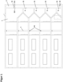
- the building according to the invention comprises at least one vertical shaft 2 with at least two passages 21 and a pressurization system ( Figure 1 ).
- Each passage 21 is suitable for connecting the shaft 2 with the vertical access connection 1 and has, on the one hand, a shaft opening 211 which opens into the shaft 2 and, on the other hand, a connecting opening 212 which is suitable for connection with the vertical access connection 1.
- the shaft openings 211 of the passages 21 are arranged at different heights of the shaft 2 and the connecting openings 212 are suitable for arrangement at different heights of the vertical access connection 1.
- the pressurization system comprises at least one fan unit 3 for each passage 21, with which air can be selectively conveyed from the shaft 2 into the vertical Access connection 1 or from the vertical access connection 1 into the shaft 2.
- Each fan unit 3 can be controlled individually and independently of the other fan units 3 and can convey air in both directions (not simultaneously, but selectively in one direction or the other).
- the shaft 2 is also connected in its lower area via an air inlet 22 to an outside area of the building directly or via a duct, so that outside air can enter the shaft 2 through the air inlet.
- This air inlet 22 can, if necessary, be provided with flaps or fans to close, control, or promote the passage of air.
- the shaft 2 has a low aerodynamic impedance between the shaft openings 211 in order to ensure unhindered air movement in both directions within the shaft 2. This can be achieved by a uniform, for example, round or square diameter of the shaft 2 and by the absence of obstacles in the shaft 2.
- the shaft 2 is not an elevator shaft in which an elevator car is located and in which, depending on the position and/or movement of the elevator car in the elevator shaft, the vertical movement of the air is severely impaired.
- the shaft is an additional shaft for the purpose of air conveyance and distribution in the vertical Access connection 1.
- the building is provided with a vertical ventilation duct 4 with air outlets 41 through which air can escape from the building.
- the air outlets 41 are preferably located on each floor and in the room immediately adjacent to the vertical access connection 1. Additionally or alternatively, air can also flow out of the building via other routes, for example, via an open facade.
- the fire floor is identified and a first fan unit 3, which is located near the fire floor, is put into operation in such a way that air is conveyed through a first passage 21 from the shaft 2 into the vertical access connection 1 ( Figure 2a ).
- the invention provides for several smaller, independent fan units 3 that are specifically activated to generate an overpressure in the desired area of the vertical access connection 1 under the simultaneous influence of disruptive factors such as thermals, open doors, etc.
- the advantage of this is that the fan units 3 can generate the same overpressure in the stairwell and on the fire floor with a lower output as a central smoke protection pressure system, and that no space is required for a bulky central smoke protection pressure system.
- the fire floor can be identified using any conventional method from the prior art using fire sensors, etc.
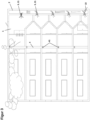
- At least one first fan unit 3, which is located near the fire floor, is put into operation in such a way that air is conveyed through a first passage 21 from the shaft 2 into the vertical access connection 1 and at least one supporting fan unit 3, which is remote from the fire floor, is operated in such a way that air is conveyed through a second passage 21 in reverse from the vertical access connection 1 into the shaft 2 ( Figure 3 ).
- This overpressure supports the first fan unit 3 and increases the air flow through the first opening 21 and the overpressure generated in the vertical access connection 1 in the area of the fire floor. This also equalizes the pressure conditions in the access connection 1 compared to shaft 2.
- the first and the supporting fan unit 3 therefore work together, and their outputs are added together.
- the overall output of the pressurization system can be continually and flexibly increased. This results in a swarm effect, according to which individual small units work together to achieve a powerful overall effect.
- the invention has the advantage over the prior art that a large number of small fan units 3 can be used, which are inexpensive, more compact and easier to install than a large, central Smoke protection pressurization system.
- the vertical access connection 1 is connected to the shaft 2 via a passage 21 on several floors, preferably on each floor, and each passage 21 is provided with its own fan unit 3.
- each passage 21 is provided with its own fan unit 3.
- the fan units 3 of the vents on the two floors below can also transport air through the respective vent 21 from the shaft 2 into the vertical access connection 1.
- the fan units 3 of the vents on the two floors above can also transport air through the respective vent 21 from the shaft 2 into the vertical access connection 1.
- one or more further fan units 3, for example all other fan units 3 of the building can convey air through the respective passages 21 from the vertical access connection 1 into the shaft 2, as already described above.
- the fan units 3 of two or more directly adjacent floors do not act against each other, ie that no fan unit 3 draws air from the shaft 2 into the vertical access connection 1 and the other, conversely, transports air from the vertical access connection 1 into the shaft 2.
- the fan units 3 of two or more immediately adjacent floors would be so close to one another that their effects would virtually cancel each other out. To avoid this, it is advantageous if there is one or more neutral, non-acting fan units 3 between two opposing fan units 3.
- each fan unit 3 is provided with a controllable flap with which the corresponding passage 21 can be closed in such a way that no passage of air can take place between the shaft 2 and the vertical access connection 1. It is therefore advantageous if the flap of a neutral fan unit is closed.
- the damper or the fan speed control can also be used to regulate the performance of the fan unit, e.g., to create a slightly lower overpressure in the floor above and below the fire floor, or in a very tall building, only a defined number of fan units are activated, depending on the fire floor or other criteria.
- the damper can be designed in a variety of ways and has, for example, a series of slats 32 arranged next to one another like a blind, which can be pivoted between an open and a closed position ( Figure 5 ).
- a flap can further increase the reaction speed of the fan unit, since opening and closing the flap is much easier and faster than increasing and reducing the speed of the fan.
- a fan unit 3 may comprise one or more fans 31.
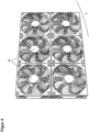
- a fan unit 3 comprises a plurality of fans 31 arranged side by side (see Figure 4 ).
- the provision of a fan unit 3 with several small fans 31 is preferred because it would still be partially operational even if individual fans 31 fail and is therefore very reliable.
- a fan unit 3 with a single fan 31, on the other hand, would no longer be operational if this single fan 31 fails.
- the fans 31 can all be connected in parallel or can be controlled individually. In the embodiments of the invention with a flap, it can be advantageous to provide each fan 31 with its own flap.
- the pressurization system comprises at least one pressure sensor for controlling/regulating the pressurization system. It is particularly advantageous if each fan unit is provided with a sensor for determining the pressure difference between the vertical access connection in the area of the corresponding connection opening 212 and/or the outside area of the building and/or the stairwell or the airlock or the usable areas.
- the performance of the fan unit, the flap and the individual fans can be controlled according to a predefined setpoint and based on the determined pressure difference or based on another controlled variable, for example depending on a door position (for example by controlling the speed of the fans, by adjusting the air flow direction and/or by operating dampers).
- the predefined setpoint can be selected, for example, from a predefined list of setpoints suitable for different situations, e.g., outside temperature, time of year.
- a predefined list of setpoints suitable for different situations e.g., outside temperature, time of year.
- One of these situations is, for example, when the fan unit is located on the fire floor.
- the setpoint corresponds to the overpressure to be achieved on the fire floor.
- Another situation is, for example, when the fan unit is located on a floor adjacent to the fire floor. In this case, the setpoint can be lower than the overpressure to be achieved on the fire floor.
- all fans 31 of a fan unit 3 can be activated, for example.
- the desired overpressure is reached, only a portion of the power of the fans 31 of the fan unit 3 is required to maintain the overpressure, so that some of the fans 1 can be switched off, or the speed of certain fans 31 can be reduced, or the associated damper can be completely or partially closed.
- the pressure in the vertical access connection 1 may then also vary, especially if a door of the vertical access connection 1 is opened and air escapes quickly from the vertical access connection 1.
- additional fans 31 can be dynamically switched on or off depending on the desired flow direction and/or individual flaps can be opened and closed more or less.
- a central controller can be provided to control the pressurization system, or the fan units 3 can communicate with each other and operate in a coordinated manner. This is particularly advantageous because the fan units 3 are then not dependent on a controller and can operate autonomously.
- Each fan unit 3 could be able to communicate with all other fan units 3 or only with the neighboring fan units 3. In the latter case, communications could propagate from fan unit 3 to fan unit 3.
- each fan unit functions autonomously according to predetermined setpoints, so that they only receive an instruction when a fire signal is triggered, for example, which triggers the start-up of the fans and specifies the selection of the appropriate setpoint depending on the operating mode and the control system.
- an advantageous embodiment of the invention provides for one or more fan units 3 to be provided with soundproofing, which serves to dampen the noise generated by the fans. This is achieved, for example, by optimizing the speeds and/or louvers 32 in front of the fan unit 3.
- the passages 21 can be designed differently depending on the embodiment of the invention. In particular, they do not need to have a minimum length and can also be simple openings if the shaft 2 and the vertical access connection 1 are located directly adjacent to each other.
Landscapes
- Engineering & Computer Science (AREA)
- Chemical & Material Sciences (AREA)
- Combustion & Propulsion (AREA)
- Mechanical Engineering (AREA)
- General Engineering & Computer Science (AREA)
- Architecture (AREA)
- Civil Engineering (AREA)
- Structural Engineering (AREA)
- Respiratory Apparatuses And Protective Means (AREA)
- Ventilation (AREA)
Claims (11)
- Bâtiment à plusieurs étages avec un système pour maintenir hors de fumée un accès vertical (1) du bâtiment, comprenant au moins un conduit vertical (2) avec au moins deux passages (21) et un système de pressurisation,dans lequel chaque passage (21) relie le conduit (2) à l'accès vertical (1) et présente d'une part une ouverture de conduit (211) qui débouche dans le conduit (2) et d'autre part une ouverture d'accès (212) qui est reliée à l'accès vertical (1),dans lequel les ouvertures de conduit (211) des passages (21) sont disposées à différentes hauteurs du conduit (2) et les ouvertures d'accès (212) sont disposées à différentes hauteurs de l'accès vertical (1),dans lequel l'accès vertical (1) est relié au conduit par un passage (21) dans plusieurs étages,dans lequel le système de pressurisation comprend au moins une unité de ventilation (3) pour chaque passage (21), avec laquelle de l'air peut être soufflé depuis le puits (2) dans l'accès vertical (1),caractérisé en ce queau moins une unité de ventilation (3) est également conçue pour acheminer l'air de l'accès (1) dans le puits (2) et peut être commandée pour acheminer l'air sélectivement dans l'une ou l'autre direction.
- Bâtiment selon la revendication 1,
caractérisé en ce que
chaque unité de ventilation (3) peut être commandée individuellement et indépendamment des autres unités de ventilateur (3) et peut acheminer de l'air dans les deux directions. - Bâtiment selon la revendication 1,
caractérisé en ce que
le conduit (2) comporte un passage qui le raccorde à l'accès vertical (1) pour chaque étage du bâtiment. - Bâtiment selon la revendication 1,
caractérisé en ce que
une unité de ventilation (3) comporte une pluralité de ventilateurs (31) disposés côte à côte dans le même plan. - Bâtiment selon la revendication 1,
caractérisé en ce que
une unité de ventilation (3) est pourvue d'un volet commandable avec lequel le passage (21) peut être fermé de telle manière qu'aucun passage d'air ne puisse avoir lieu entre le conduit (2) et la cage d'escalier (1). - Bâtiment selon la revendication 5,
caractérisé en ce que
le volet comporte une série de lamelles (32) disposées les unes à côté des autres qui peuvent pivoter entre une position ouverte et une position fermée. - Bâtiment selon la revendication 1,
caractérisé en ce que
une unité de ventilation (3) est pourvue d'une isolation phonique qui sert à amortir le bruit généré par les ventilateurs (31). - Procédé pour maintenir hors de fumée un accès vertical (1) d'un bâtiment à plusieurs étages selon la revendication 1 en cas d'incendie,
caractérisé par les étapes suivantes :• l'étage en feu est identifié ;• une première unité de ventilation (3) située à proximité de l'étage en feu est mise en service de telle manière que l'air est transporté à travers un premier passage (21) depuis le puits (2) dans l'accès vertical (1) ; et• en plus de la première unité de ventilation (3), au moins une unité de ventilation d'assistance (3) éloignée de l'étage en feu est mise en service de telle manière que l'air est acheminé à travers un deuxième passage (21) depuis l'accès vertical (1) dans le conduit (2). - Procédé selon la revendication 8,
caractérisé en ce queil y a au moins une unité de ventilation neutre et non active (3) entre deux unités de ventilation fonctionnant dans des directions opposées (3),cette unité de ventilation neutre (3) est munie d'un volet commandable avec lequel le passage correspondant (21) est fermé de telle manière qu'aucun passage d'air ne puisse avoir lieu entre le conduit (2) et l'accès vertical (1). - Procédé selon la revendication 8 ou la revendication 9,
caractérisé en ce que
des changements de pression dans l'accès vertical sont détectés et la puissance du système de pressurisation est ajustée en réponse en activant ou désactivant dynamiquement des unités de ventilation (3) et en modifiant les débits volumiques. - Procédé selon la revendication 8,
caractérisé en ce que
en hiver comme en été, le système de pressurisation contrecarre le flux d'air spontané, induit thermiquement, qui règne dans l'accès vertical (1).
Applications Claiming Priority (1)
| Application Number | Priority Date | Filing Date | Title |
|---|---|---|---|
| CH001226/2022A CH720129A2 (de) | 2022-10-17 | 2022-10-17 | System und Verfahren zur Rauchfreihaltung einer vertikalen Zugangsverbindung eines mehrgeschossigen Gebäudes |
Publications (3)
| Publication Number | Publication Date |
|---|---|
| EP4357689A1 EP4357689A1 (fr) | 2024-04-24 |
| EP4357689C0 EP4357689C0 (fr) | 2025-04-02 |
| EP4357689B1 true EP4357689B1 (fr) | 2025-04-02 |
Family
ID=88417377
Family Applications (1)
| Application Number | Title | Priority Date | Filing Date |
|---|---|---|---|
| EP23203908.1A Active EP4357689B1 (fr) | 2022-10-17 | 2023-10-16 | Système et procédé de libération de fumée d'une liaison d'accès verticale d'un bâtiment à plusieurs étages |
Country Status (2)
| Country | Link |
|---|---|
| EP (1) | EP4357689B1 (fr) |
| CH (1) | CH720129A2 (fr) |
Family Cites Families (3)
| Publication number | Priority date | Publication date | Assignee | Title |
|---|---|---|---|---|
| DE20113242U1 (de) * | 2001-08-09 | 2001-10-31 | Ostertag, Dieter, Dr.-Ing., 82396 Pähl | Sicherheitstreppenraum für ein Hochhaus |
| WO2016034415A1 (fr) | 2014-09-05 | 2016-03-10 | Swiss Raltec Gmbh | Immeuble de grande taille comprenant n étages et un puits d'évacuation |
| KR20180109269A (ko) * | 2017-03-27 | 2018-10-08 | 한국토지주택공사 | 건축구조물의 제연장치 |
-
2022
- 2022-10-17 CH CH001226/2022A patent/CH720129A2/de unknown
-
2023
- 2023-10-16 EP EP23203908.1A patent/EP4357689B1/fr active Active
Also Published As
| Publication number | Publication date |
|---|---|
| EP4357689C0 (fr) | 2025-04-02 |
| EP4357689A1 (fr) | 2024-04-24 |
| CH720129A2 (de) | 2024-04-30 |
Similar Documents
| Publication | Publication Date | Title |
|---|---|---|
| DE69824602T2 (de) | Integrale luftauslassmodule und dazugehörige heiz- und kühlsysteme | |
| EP2664865B1 (fr) | Appareil d'aération pour l'aération et la purge d'air et procédé d'aération et de purge d'air | |
| EP3222575A1 (fr) | Systeme et procédé pour pour l'aération et l'évacuation des fumées dans une cage d'ascenseur | |
| EP2194329B1 (fr) | Appareil de ventilation ainsi que procédé de fonctionnement de l'appareil de ventilation | |
| EP1571402B1 (fr) | Appareil de traitement de l'air d'une pièce pour chauffer, refroidir et/ou ventiler une pièce et méthode correspondante | |
| EP3370491B1 (fr) | Système de refroidissement destiné au refroidissement d'une armoire de serveur disposée dans un espace | |
| EP4357689A1 (fr) | Système et procédé de libération de fumée d'une liaison d'accès verticale d'un bâtiment à plusieurs étages | |
| EP3078918B1 (fr) | Installation de pression différentielle hybride de protection contre la fumée et procédé pour maintenir une pression différentielle | |
| DE2049760B2 (de) | Luftklimatisierungssystem | |
| DE3728698A1 (de) | Klimaanlage | |
| EP0756138B1 (fr) | Elément plat de chauffage ou de refroidissement | |
| EP0657702B1 (fr) | Dispositif pour la génération de deux rideaux d'air à sens de circulation opposée | |
| DE202016101525U1 (de) | Aufzugsschachtbelüftung und -entrauchung | |
| EP2505735B1 (fr) | Installation pressurisée de protection contre la fumée et procédé de maintien sans fumée d'une sortie de secours | |
| AT500559B1 (de) | Raumlufttechnische einrichtung | |
| EP0877209B1 (fr) | Dispositif de ventilation pour un bâtiment | |
| EP0607116B1 (fr) | Pièce de bout pour climatiseurs pour locaux | |
| EP1440242B1 (fr) | Protection de locaux contre la fumee | |
| DE202008016732U1 (de) | Raumlufttechnisches Gerät | |
| DE19719367A1 (de) | Gebäude | |
| EP0358121A2 (fr) | Fenêtre aérée | |
| DE29708247U1 (de) | Gebäude | |
| EP1619449A1 (fr) | Appareil et méthode de ventilation pour chauffer, refroidir et/ou ventiler une pièce | |
| DE2630504A1 (de) | Anordnung zur klimatisierung und belueftung von raeumen | |
| DD296151A5 (de) | Entlueftungsanlage |
Legal Events
| Date | Code | Title | Description |
|---|---|---|---|
| PUAI | Public reference made under article 153(3) epc to a published international application that has entered the european phase |
Free format text: ORIGINAL CODE: 0009012 |
|
| STAA | Information on the status of an ep patent application or granted ep patent |
Free format text: STATUS: THE APPLICATION HAS BEEN PUBLISHED |
|
| STAA | Information on the status of an ep patent application or granted ep patent |
Free format text: STATUS: REQUEST FOR EXAMINATION WAS MADE |
|
| AK | Designated contracting states |
Kind code of ref document: A1 Designated state(s): AL AT BE BG CH CY CZ DE DK EE ES FI FR GB GR HR HU IE IS IT LI LT LU LV MC ME MK MT NL NO PL PT RO RS SE SI SK SM TR |
|
| 17P | Request for examination filed |
Effective date: 20240327 |
|
| RBV | Designated contracting states (corrected) |
Designated state(s): AL AT BE BG CH CY CZ DE DK EE ES FI FR GB GR HR HU IE IS IT LI LT LU LV MC ME MK MT NL NO PL PT RO RS SE SI SK SM TR |
|
| GRAP | Despatch of communication of intention to grant a patent |
Free format text: ORIGINAL CODE: EPIDOSNIGR1 |
|
| STAA | Information on the status of an ep patent application or granted ep patent |
Free format text: STATUS: GRANT OF PATENT IS INTENDED |
|
| INTG | Intention to grant announced |
Effective date: 20241031 |
|
| GRAS | Grant fee paid |
Free format text: ORIGINAL CODE: EPIDOSNIGR3 |
|
| GRAA | (expected) grant |
Free format text: ORIGINAL CODE: 0009210 |
|
| STAA | Information on the status of an ep patent application or granted ep patent |
Free format text: STATUS: THE PATENT HAS BEEN GRANTED |
|
| AK | Designated contracting states |
Kind code of ref document: B1 Designated state(s): AL AT BE BG CH CY CZ DE DK EE ES FI FR GB GR HR HU IE IS IT LI LT LU LV MC ME MK MT NL NO PL PT RO RS SE SI SK SM TR |
|
| REG | Reference to a national code |
Ref country code: GB Ref legal event code: FG4D Free format text: NOT ENGLISH |
|
| REG | Reference to a national code |
Ref country code: CH Ref legal event code: EP |
|
| REG | Reference to a national code |
Ref country code: IE Ref legal event code: FG4D Free format text: LANGUAGE OF EP DOCUMENT: GERMAN |
|
| REG | Reference to a national code |
Ref country code: DE Ref legal event code: R096 Ref document number: 502023000773 Country of ref document: DE |
|
| U01 | Request for unitary effect filed |
Effective date: 20250429 |
|
| U07 | Unitary effect registered |
Designated state(s): AT BE BG DE DK EE FI FR IT LT LU LV MT NL PT RO SE SI Effective date: 20250507 |
|
| PG25 | Lapsed in a contracting state [announced via postgrant information from national office to epo] |
Ref country code: ES Free format text: LAPSE BECAUSE OF FAILURE TO SUBMIT A TRANSLATION OF THE DESCRIPTION OR TO PAY THE FEE WITHIN THE PRESCRIBED TIME-LIMIT Effective date: 20250402 |
|
| PG25 | Lapsed in a contracting state [announced via postgrant information from national office to epo] |
Ref country code: GR Free format text: LAPSE BECAUSE OF FAILURE TO SUBMIT A TRANSLATION OF THE DESCRIPTION OR TO PAY THE FEE WITHIN THE PRESCRIBED TIME-LIMIT Effective date: 20250703 Ref country code: NO Free format text: LAPSE BECAUSE OF FAILURE TO SUBMIT A TRANSLATION OF THE DESCRIPTION OR TO PAY THE FEE WITHIN THE PRESCRIBED TIME-LIMIT Effective date: 20250702 |
|
| PG25 | Lapsed in a contracting state [announced via postgrant information from national office to epo] |
Ref country code: PL Free format text: LAPSE BECAUSE OF FAILURE TO SUBMIT A TRANSLATION OF THE DESCRIPTION OR TO PAY THE FEE WITHIN THE PRESCRIBED TIME-LIMIT Effective date: 20250402 |
|
| PG25 | Lapsed in a contracting state [announced via postgrant information from national office to epo] |
Ref country code: HR Free format text: LAPSE BECAUSE OF FAILURE TO SUBMIT A TRANSLATION OF THE DESCRIPTION OR TO PAY THE FEE WITHIN THE PRESCRIBED TIME-LIMIT Effective date: 20250402 |
|
| PG25 | Lapsed in a contracting state [announced via postgrant information from national office to epo] |
Ref country code: RS Free format text: LAPSE BECAUSE OF FAILURE TO SUBMIT A TRANSLATION OF THE DESCRIPTION OR TO PAY THE FEE WITHIN THE PRESCRIBED TIME-LIMIT Effective date: 20250702 |
|
| PG25 | Lapsed in a contracting state [announced via postgrant information from national office to epo] |
Ref country code: IS Free format text: LAPSE BECAUSE OF FAILURE TO SUBMIT A TRANSLATION OF THE DESCRIPTION OR TO PAY THE FEE WITHIN THE PRESCRIBED TIME-LIMIT Effective date: 20250802 |
|
| U20 | Renewal fee for the european patent with unitary effect paid |
Year of fee payment: 3 Effective date: 20251008 |
|
| PG25 | Lapsed in a contracting state [announced via postgrant information from national office to epo] |
Ref country code: SM Free format text: LAPSE BECAUSE OF FAILURE TO SUBMIT A TRANSLATION OF THE DESCRIPTION OR TO PAY THE FEE WITHIN THE PRESCRIBED TIME-LIMIT Effective date: 20250402 |
|
| PG25 | Lapsed in a contracting state [announced via postgrant information from national office to epo] |
Ref country code: CZ Free format text: LAPSE BECAUSE OF FAILURE TO SUBMIT A TRANSLATION OF THE DESCRIPTION OR TO PAY THE FEE WITHIN THE PRESCRIBED TIME-LIMIT Effective date: 20250402 |
|
| PG25 | Lapsed in a contracting state [announced via postgrant information from national office to epo] |
Ref country code: SK Free format text: LAPSE BECAUSE OF FAILURE TO SUBMIT A TRANSLATION OF THE DESCRIPTION OR TO PAY THE FEE WITHIN THE PRESCRIBED TIME-LIMIT Effective date: 20250402 |
|
| PLBE | No opposition filed within time limit |
Free format text: ORIGINAL CODE: 0009261 |
|
| STAA | Information on the status of an ep patent application or granted ep patent |
Free format text: STATUS: NO OPPOSITION FILED WITHIN TIME LIMIT |
|
| REG | Reference to a national code |
Ref country code: CH Ref legal event code: L10 Free format text: ST27 STATUS EVENT CODE: U-0-0-L10-L00 (AS PROVIDED BY THE NATIONAL OFFICE) Effective date: 20260211 |
|
| 26N | No opposition filed |
Effective date: 20260105 |